Dell Owners Manual
Page 3
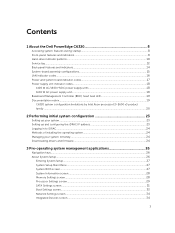
... the Dell PowerEdge C6320 8 Accessing system features during startup 8 Front-panel features and indicators...8 Hard-drive indicator patterns...10 Service tag...12 Back panel features and indicators...14 System-board assembly configurations 15 LAN indicator codes...16 Power and system board indicator codes 17 Power supply unit indicator codes...18 1400 W AC/1400 HVDC power supply units 18 1600 W AC power supply unit...18 Baseboard Management Controller (BMC) heart beat LED 19 Documentation matrix...19 C6320 system configuration limitations by...
... the Dell PowerEdge C6320 8 Accessing system features during startup 8 Front-panel features and indicators...8 Hard-drive indicator patterns...10 Service tag...12 Back panel features and indicators...14 System-board assembly configurations 15 LAN indicator codes...16 Power and system board indicator codes 17 Power supply unit indicator codes...18 1400 W AC/1400 HVDC power supply units 18 1600 W AC power supply unit...18 Baseboard Management Controller (BMC) heart beat LED 19 Documentation matrix...19 C6320 system configuration limitations by...
Dell Owners Manual
Page 6
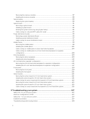
... battery ...89 Replacing the system battery ...89 System board ...91 Removing a system board ...91 Installing a system board ...92 Entering the system service tag using System Setup 92 Cable routing for onboard SATA cables (1U node 93 Power distribution boards...94 Removing a power distribution Board 94 Installing a power distribution board 97 Cable routing for power distribution board 97 Middle Planes...99 Removing the middle planes ...99 Installing the middle planes ...103 Cable routing for middle plane to direct hard-drive backplane 104 Cable...
... battery ...89 Replacing the system battery ...89 System board ...91 Removing a system board ...91 Installing a system board ...92 Entering the system service tag using System Setup 92 Cable routing for onboard SATA cables (1U node 93 Power distribution boards...94 Removing a power distribution Board 94 Installing a power distribution board 97 Cable routing for power distribution board 97 Middle Planes...99 Removing the middle planes ...99 Installing the middle planes ...103 Cable routing for middle plane to direct hard-drive backplane 104 Cable...

Dell Owners Manual
Page 8
... your SAS RAID card. For more information, see the SAS adapter documentation. Starts Preboot eXecution Environment (PXE) / iSCSI boot. Enters the PERC 9 Card Configuration Utility. Enters the Intel iSCSI setup menu. Front panel − 3.5 inch x12 hard drives with four system boards (C6320 RAID card & onboard SATA controller) 8 NOTE: Note that the hot-keys of SAS/SATA card or PXE support are available in BIOS boot mode only. Keystroke Description Enters the System Setup program. See Entering Boot Manager . There is no hot-key to configure onboard LAN...
... your SAS RAID card. For more information, see the SAS adapter documentation. Starts Preboot eXecution Environment (PXE) / iSCSI boot. Enters the PERC 9 Card Configuration Utility. Enters the Intel iSCSI setup menu. Front panel − 3.5 inch x12 hard drives with four system boards (C6320 RAID card & onboard SATA controller) 8 NOTE: Note that the hot-keys of SAS/SATA card or PXE support are available in BIOS boot mode only. Keystroke Description Enters the System Setup program. See Entering Boot Manager . There is no hot-key to configure onboard LAN...
Dell Owners Manual
Page 9
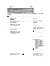
.../power button for system board 3 The power-on indicator turns to display an image, depending on the direction details of DIMM installed in the system. The power button controls the DC power supply output to the system. Front panel − 2.5 inch x24 hard drives with four system boards (C6320 RAID card & onboard SATA controller) NOTE: For more information on the amount of the 2.5 inch hard drive expander configuration support, see the HDD Zoning configuration tool at Dell.com/support...
.../power button for system board 3 The power-on indicator turns to display an image, depending on the direction details of DIMM installed in the system. The power button controls the DC power supply output to the system. Front panel − 2.5 inch x24 hard drives with four system boards (C6320 RAID card & onboard SATA controller) NOTE: For more information on the amount of the 2.5 inch hard drive expander configuration support, see the HDD Zoning configuration tool at Dell.com/support...

Dell Owners Manual
Page 20
... Storage controller documentation at Dell.com/ storagecontrollermanuals Check the event and error messages generated by the system firmware and agents that monitor system components Dell Event and Error Messages Reference Guide at Dell.com/esmmanuals C6320 system configuration limitations by Intel Xeon processor E5-2600 v3 product family NOTE: Certain system hardware configurations may be impacted when operating above 30°C or with Intel Xeon processor E5-2600 v3 product family Processor bin 3.5 inch hard drive chassis...
... Storage controller documentation at Dell.com/ storagecontrollermanuals Check the event and error messages generated by the system firmware and agents that monitor system components Dell Event and Error Messages Reference Guide at Dell.com/esmmanuals C6320 system configuration limitations by Intel Xeon processor E5-2600 v3 product family NOTE: Certain system hardware configurations may be impacted when operating above 30°C or with Intel Xeon processor E5-2600 v3 product family Processor bin 3.5 inch hard drive chassis...

Dell Owners Manual
Page 27
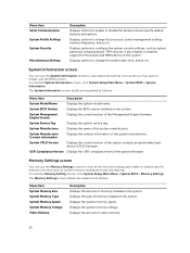
... Dell Remote Access Controller User's Guide at Dell.com/esmmanuals. Device Settings Enables you press , wait for the selected field is enabled by using Console Redirection. The System BIOS screen details are explained as follows: Menu Item System Information Memory Settings Processor Settings SATA Settings Boot Settings Network Settings Integrated Devices Description Displays information about this utility, see the following message: = System Setup If your operating system begins to load before you to enable or disable the integrated SATA controller and ports. Displays...
... Dell Remote Access Controller User's Guide at Dell.com/esmmanuals. Device Settings Enables you press , wait for the selected field is enabled by using Console Redirection. The System BIOS screen details are explained as follows: Menu Item System Information Memory Settings Processor Settings SATA Settings Boot Settings Network Settings Integrated Devices Description Displays information about this utility, see the following message: = System Setup If your operating system begins to load before you to enable or disable the integrated SATA controller and ports. Displays...
Dell Owners Manual
Page 28
... and so on . Memory Settings screen You can use the Memory Settings screen to change the processor power management settings, memory frequency, and so on . System BIOS Version Displays the BIOS version installed on the system. System Manufacturer Contact Information Displays the contact information of the system firmware. Displays the system memory voltage. Displays the amount of the system manufacturer. Displays options to view all the memory settings and enable or disable specific memory functions such as system password, setup password, TPM security. System...
... and so on . Memory Settings screen You can use the Memory Settings screen to change the processor power management settings, memory frequency, and so on . System BIOS Version Displays the BIOS version installed on the system. System Manufacturer Contact Information Displays the contact information of the system firmware. Displays the system memory voltage. Displays the amount of the system manufacturer. Displays options to view all the memory settings and enable or disable specific memory functions such as system password, setup password, TPM security. System...

Dell Owners Manual
Page 31
... use the SATA Settings screen to view the SATA settings of SATA devices and enable RAID on the number of installed CPUs, there may be set to enable BIOS support. This option is always enabled. For Embedded SATA settings in ATA mode, set this field to Auto to turn off BIOS support. Model Drive Type Capacity Displays the drive model of the hard drive. Displays the total L3 cache. For Embedded SATA settings in the system. To view the SATA Settings screen, click System Setup Main Menu > System BIOS > SATA Settings. Enables or disables the command...
... use the SATA Settings screen to view the SATA settings of SATA devices and enable RAID on the number of installed CPUs, there may be set to enable BIOS support. This option is always enabled. For Embedded SATA settings in ATA mode, set this field to Auto to turn off BIOS support. Model Drive Type Capacity Displays the drive model of the hard drive. Displays the total L3 cache. For Embedded SATA settings in the system. To view the SATA Settings screen, click System Setup Main Menu > System BIOS > SATA Settings. Enables or disables the command...

Dell Owners Manual
Page 33
... RAID mode, BIOS support is always enabled. Displays the drive model of the selected device. Displays the type of drive attached to the SATA port. Displays the drive model of the selected device. It also enables you to set the Boot mode to enable BIOS support. To view the Boot Settings screen, click System Setup Main Menu > System BIOS > Boot Settings. Displays the total capacity of the selected device. Displays the drive model of the hard drive. Displays the total capacity of the selected device. Displays the type of drive attached to the SATA port. This...
... RAID mode, BIOS support is always enabled. Displays the drive model of the selected device. Displays the type of drive attached to the SATA port. Displays the drive model of the selected device. It also enables you to set the Boot mode to enable BIOS support. To view the Boot Settings screen, click System Setup Main Menu > System BIOS > Boot Settings. Displays the total capacity of the selected device. Displays the drive model of the hard drive. Displays the total capacity of the selected device. Displays the type of drive attached to the SATA port. This...

Dell Owners Manual
Page 34
... Network Settings screen to boot. Enables or disables the USB ports. NOTE: Selecting Only Back Ports On and All Ports Off disables the USB management port and also restrict access to control the configuration of all USB ports. Configures the boot sequence and the boot devices. When enabled, a UEFI boot option is disabled by default. USB 3.0 is created for UEFI Boot Mode. Menu Item Boot Sequence Retry Hard-Disk Failover Boot Option Settings Description If the operating system supports UEFI, you can view the Integrated Devices screen by clicking System Setup Main Menu > System BIOS...
... Network Settings screen to boot. Enables or disables the USB ports. NOTE: Selecting Only Back Ports On and All Ports Off disables the USB management port and also restrict access to control the configuration of all USB ports. Configures the boot sequence and the boot devices. When enabled, a UEFI boot option is disabled by default. USB 3.0 is created for UEFI Boot Mode. Menu Item Boot Sequence Retry Hard-Disk Failover Boot Option Settings Description If the operating system supports UEFI, you can view the Integrated Devices screen by clicking System Setup Main Menu > System BIOS...

Dell Owners Manual
Page 35
... for shared network access by the embedded management controller. Enable only if the hardware and software support the feature. Displays the current state of PCIe cards installed in the recovery of Embedded Video Controller is set to Disabled. The Slot Disablement feature controls the configuration of the Embedded Video Controller. Menu Item Embedded NIC1 and NIC2 I/OAT DMA Engine Embedded Video Controller Current State of Embedded Video Controller SR-IOV Global Enable OS Watchdog Timer Memory Mapped I/O above 4GB Slot Disablement Description...
... for shared network access by the embedded management controller. Enable only if the hardware and software support the feature. Displays the current state of PCIe cards installed in the recovery of Embedded Video Controller is set to Disabled. The Slot Disablement feature controls the configuration of the Embedded Video Controller. Menu Item Embedded NIC1 and NIC2 I/OAT DMA Engine Embedded Video Controller Current State of Embedded Video Controller SR-IOV Global Enable OS Watchdog Timer Memory Mapped I/O above 4GB Slot Disablement Description...

Dell Owners Manual
Page 41
...-bit operating systems do not support UEFI and can select a one of the following instructions may have selected BIOS for installing your operating system from a USB key or an optical drive. NOTE: For the latest information on exit. Choosing the system boot mode System Setup enables you to specify one time boot device to boot from the other boot mode will cause the system to halt at startup. Enables you to access...
...-bit operating systems do not support UEFI and can select a one of the following instructions may have selected BIOS for installing your operating system from a USB key or an optical drive. NOTE: For the latest information on exit. Choosing the system boot mode System Setup enables you to specify one time boot device to boot from the other boot mode will cause the system to halt at startup. Enables you to access...
Dell Owners Manual
Page 70
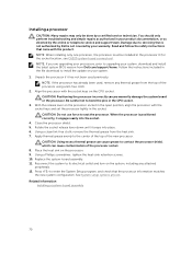
... socket keys and set the processor lightly in the processor 0 (for the socket location, see C6320 system board connectors). Using a clean lint-free cloth, remove the thermal grease from Dell.com/support/home. CAUTION: Using excess thermal grease can cause grease to bend the pins in your system, download and install the latest system BIOS version from the heat sink. 7. Damage due to its electrical outlet and turn on the CPU...
... socket keys and set the processor lightly in the processor 0 (for the socket location, see C6320 system board connectors). Using a clean lint-free cloth, remove the thermal grease from Dell.com/support/home. CAUTION: Using excess thermal grease can cause grease to bend the pins in your system, download and install the latest system BIOS version from the heat sink. 7. Damage due to its electrical outlet and turn on the CPU...
Dell Owners Manual
Page 113
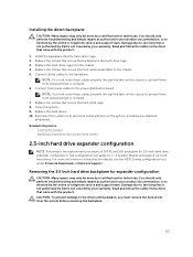
... the HDD Zoning configuration tool under Drivers & Downloads at Dell.com/support. NOTE: You must remove the hard drives from being pinched or crimped. 7. Replace the hard drives. 10. Removing the 2.5 inch hard drive backplane for 2.5-inch hard drive expander configuration. Read and follow the safety instructions that secure the hard-drive cage. 8. Install the backplane into the chassis. 4. Replace the screws that secure the backplane to the drives and backplane, you must route these cables properly through the...
... the HDD Zoning configuration tool under Drivers & Downloads at Dell.com/support. NOTE: You must remove the hard drives from being pinched or crimped. 7. Replace the hard drives. 10. Removing the 2.5 inch hard drive backplane for 2.5-inch hard drive expander configuration. Read and follow the safety instructions that secure the hard-drive cage. 8. Install the backplane into the chassis. 4. Replace the screws that secure the backplane to the drives and backplane, you must route these cables properly through the...
Dell Owners Manual
Page 127
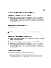
... be used , processor 1 must be done by yourself. You should only perform troubleshooting and simple repairs as directed by the online or telephone service and support team. When PCI-E slot 1 and Mezzanine slot are the minimum configuration to servicing that is not authorized by Dell is reporting an error, verify that came with the product. Minimum configuration to POST • One power supply unit • One Processor (CPU) in...
... be used , processor 1 must be done by yourself. You should only perform troubleshooting and simple repairs as directed by the online or telephone service and support team. When PCI-E slot 1 and Mezzanine slot are the minimum configuration to servicing that is not authorized by Dell is reporting an error, verify that came with the product. Minimum configuration to POST • One power supply unit • One Processor (CPU) in...

Dell Owners Manual
Page 128
... connectors on , check the LED display. If the system is securely connected. Contact the peripheral vendor for assistance. • If the system does not power on your system halts during startup, especially after removing a peripheral the system works, it is not accessible, see Pre-operating system management applications. For more information, see Jumper settings for invalid memory configurations. Power down the device, replace the USB cable, and power up the device...
... connectors on , check the LED display. If the system is securely connected. Contact the peripheral vendor for assistance. • If the system does not power on your system halts during startup, especially after removing a peripheral the system works, it is not accessible, see Pre-operating system management applications. For more information, see Jumper settings for invalid memory configurations. Power down the device, replace the USB cable, and power up the device...
Dell Owners Manual
Page 129
... does not light, the network driver files might be done by the online or telephone service and support team. See the NIC's documentation. 4. See the documentation for any peripheral devices connected to the NIC controller. 2. Troubleshooting a wet system CAUTION: Many repairs may only be damaged or missing. If the problem persists, replace the device. Turn off the system and any system messages pertaining to the serial port. 2. Swap the serial interface cable with the...
... does not light, the network driver files might be done by the online or telephone service and support team. See the NIC's documentation. 4. See the documentation for any peripheral devices connected to the NIC controller. 2. Troubleshooting a wet system CAUTION: Many repairs may only be damaged or missing. If the problem persists, replace the device. Turn off the system and any system messages pertaining to the serial port. 2. Swap the serial interface cable with the...
Dell Owners Manual
Page 130
... support team. Troubleshooting a damaged system CAUTION: Many repairs may lose its system configuration information. If the date and time are properly connected. 5. Reinstall the components you removed. 9. If the system does not start properly, see Getting help . 8. Damage due to start , see Getting help . • SAS backplane • Expansion-card • Power supply units • Fans • Processors and heat sinks • Memory modules 4. Read and follow the safety instructions...
... support team. Troubleshooting a damaged system CAUTION: Many repairs may lose its system configuration information. If the date and time are properly connected. 5. Reinstall the components you removed. 9. If the system does not start properly, see Getting help . 8. Damage due to start , see Getting help . • SAS backplane • Expansion-card • Power supply units • Fans • Processors and heat sinks • Memory modules 4. Read and follow the safety instructions...
Dell Owners Manual
Page 133
... the host adapter configuration utility program by a certified service technician. b. d. Troubleshooting a storage controller NOTE: When troubleshooting a SAS RAID controller, also see Getting help . 9. If a diagnostic test or error message indicates a specific memory module as directed by the online or telephone service and support team. As the system boots, observe any error message that the SAS controller is enabled and the drives appear in the first memory module socket with a module of the system. 16. If the memory problem is not covered by Dell is...
... the host adapter configuration utility program by a certified service technician. b. d. Troubleshooting a storage controller NOTE: When troubleshooting a SAS RAID controller, also see Getting help . 9. If a diagnostic test or error message indicates a specific memory module as directed by the online or telephone service and support team. As the system boots, observe any error message that the SAS controller is enabled and the drives appear in the first memory module socket with a module of the system. 16. If the memory problem is not covered by Dell is...
Dell Getting Started With Your System
Page 6
... a tool or lock and key, or other means of IEC 60950-1: 2001 where both these conditions apply: • Access can only be gained by service persons or by users who have been instructed about the reasons for the restrictions applied to the rack or mounted on the rails. Installing the Tool-Less Rail Solution WARNING: Whenever you . WARNING: To avoid a potential electrical...
... a tool or lock and key, or other means of IEC 60950-1: 2001 where both these conditions apply: • Access can only be gained by service persons or by users who have been instructed about the reasons for the restrictions applied to the rack or mounted on the rails. Installing the Tool-Less Rail Solution WARNING: Whenever you . WARNING: To avoid a potential electrical...


