Information Update
Page 4
3.5-Inch Chassis Update 13 Front Features and Indicators 13 Mixed SAS/SATA Hard Drive Configuration (3.5-Inch Drives Only 15 Removing a 3.5-Inch Drive Blank 15 Installing a 3.5-Inch Drive Blank 15 Removing the SAS/SATA Backplane Board . . . . 16 Installing the SAS Backplane Board 18 SAS/SATA Backplane Board Connectors . . . . . 19 4 Contents
3.5-Inch Chassis Update 13 Front Features and Indicators 13 Mixed SAS/SATA Hard Drive Configuration (3.5-Inch Drives Only 15 Removing a 3.5-Inch Drive Blank 15 Installing a 3.5-Inch Drive Blank 15 Removing the SAS/SATA Backplane Board . . . . 16 Installing the SAS Backplane Board 18 SAS/SATA Backplane Board Connectors . . . . . 19 4 Contents
Information Update
Page 5
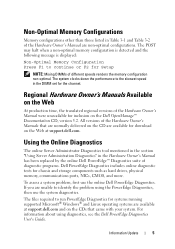
... Hardware Owner's Manual were unavailable for chassis and storage components such as hard drives, physical memory, communications ports, NICs, CMOS, and more. To assess a system problem, first use the system diagnostics. For information about using the PowerEdge Diagnostics, then use the online Dell PowerEdge Diagnostics. If you are non-optimal configurations. Regional Hardware Owner's Manuals...
... Hardware Owner's Manual were unavailable for chassis and storage components such as hard drives, physical memory, communications ports, NICs, CMOS, and more. To assess a system problem, first use the system diagnostics. For information about using the PowerEdge Diagnostics, then use the online Dell PowerEdge Diagnostics. If you are non-optimal configurations. Regional Hardware Owner's Manuals...
Information Update
Page 15
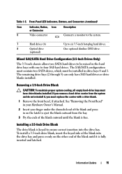
... is free. Information Update 15 Installing a 3.5-Inch Drive Blank The drive blank is fully inserted and latched. Mixed SAS/SATA Hard Drive Configuration (3.5-Inch Drives Only) The 3.5-inch chassis allows two SATA hard drives to six 3.5-inch hot-plug hard drives. Removing a 3.5-Inch Drive Blank CAUTION: To maintain proper system cooling, all empty hard-drive bays must replace the carrier with one...
... is free. Information Update 15 Installing a 3.5-Inch Drive Blank The drive blank is fully inserted and latched. Mixed SAS/SATA Hard Drive Configuration (3.5-Inch Drives Only) The 3.5-inch chassis allows two SATA hard drives to six 3.5-inch hot-plug hard drives. Removing a 3.5-Inch Drive Blank CAUTION: To maintain proper system cooling, all empty hard-drive bays must replace the carrier with one...
Information Update
Page 16
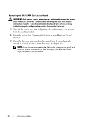
... precautions, working inside the system. NOTE: If you remove from which bay. See Figure 1-3. See "Removing a Hot-Plug Hard Drive" in your Hardware Owner's Manual. 16 Information Update Removing the SAS/SATA Backplane Board WARNING: Only trained service technicians are authorized to... record which hard drive you choose to remove the hard drives, be sure to remove the system cover and access any of the hard drives from their bays. See "Opening the System" in your Hardware Owner's Manual....
... precautions, working inside the system. NOTE: If you remove from which bay. See Figure 1-3. See "Removing a Hot-Plug Hard Drive" in your Hardware Owner's Manual. 16 Information Update Removing the SAS/SATA Backplane Board WARNING: Only trained service technicians are authorized to... record which hard drive you choose to remove the hard drives, be sure to remove the system cover and access any of the hard drives from their bays. See "Opening the System" in your Hardware Owner's Manual....
Information Update
Page 18
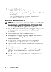
.... 1 Place the SAS backplane board so that it snaps into the securing slots on the backplane board. See "Installing the Optical Drive" in your Product Information Guide for complete information about safety precautions, working inside the system. See Figure 1-3. b While pulling the release...your Hardware Owner's Manual. 5 Reattach the SAS controller daughter card cables and the control panel cable. 6 Reinsert the hard drives. 7 If applicable, reconnect the optical drive power cable to remove the system cover and access any of the system. Installing the SAS Backplane Board WARNING: Only...
.... 1 Place the SAS backplane board so that it snaps into the securing slots on the backplane board. See "Installing the Optical Drive" in your Product Information Guide for complete information about safety precautions, working inside the system. See Figure 1-3. b While pulling the release...your Hardware Owner's Manual. 5 Reattach the SAS controller daughter card cables and the control panel cable. 6 Reinsert the hard drives. 7 If applicable, reconnect the optical drive power cable to remove the system cover and access any of the system. Installing the SAS Backplane Board WARNING: Only...
Getting Started Guide
Page 5
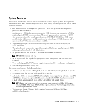
NOTE: DVD devices are available.) • Support for an integrated SAS host bus adapter, which supports up to four 2.5-inch SAS or SATA hard drives, or an optional RAID controller card with 256 MB of cache memory and a RAID battery, which supports up to a SAS or SCSI adapter, ...dell.com for an optional half-height tape backup unit (TBU) and an optional slim-line 1.44-MB diskette drive. • An optional slim-line IDE CD, DVD, or combination CD-RW/DVD drive. NOTE: System boot is opened. • Up to eight 2.5-inch, internal hot-pluggable Serial Attached SCSI (SAS) or SATA hard drives...
NOTE: DVD devices are available.) • Support for an integrated SAS host bus adapter, which supports up to four 2.5-inch SAS or SATA hard drives, or an optional RAID controller card with 256 MB of cache memory and a RAID battery, which supports up to a SAS or SCSI adapter, ...dell.com for an optional half-height tape backup unit (TBU) and an optional slim-line 1.44-MB diskette drive. • An optional slim-line IDE CD, DVD, or combination CD-RW/DVD drive. NOTE: System boot is opened. • Up to eight 2.5-inch, internal hot-pluggable Serial Attached SCSI (SAS) or SATA hard drives...

Getting Started Guide
Page 12
Memory Architecture Memory module sockets Memory module capacities Minimum RAM Maximum RAM Drives Hard drives Diskette drive Optical drive Tape drive Flash drive Connectors Back NIC Serial USB Video Front Video USB Internal USB 10 Getting Started With Your System 667-MHz registered parity DDR-II memory ...(32 GB (one processor) or 64 GB (two processors) when 8 GB memory modules are available) Up to eight 2.5-inch, hot-plug SAS or SATA internal drives One optional slimline 1.44-MB External optional USB 1.44-MB One optional slimline IDE CD, DVD, or combination CD-RW/DVD NOTE: DVD devices are...
Memory Architecture Memory module sockets Memory module capacities Minimum RAM Maximum RAM Drives Hard drives Diskette drive Optical drive Tape drive Flash drive Connectors Back NIC Serial USB Video Front Video USB Internal USB 10 Getting Started With Your System 667-MHz registered parity DDR-II memory ...(32 GB (one processor) or 64 GB (two processors) when 8 GB memory modules are available) Up to eight 2.5-inch, hot-plug SAS or SATA internal drives One optional slimline 1.44-MB External optional USB 1.44-MB One optional slimline IDE CD, DVD, or combination CD-RW/DVD NOTE: DVD devices are...
Hardware Owner's Manual
Page 3
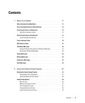
Contents 1 About Your System 11 Other Information You May Need 11 Accessing System Features During Startup 12 Front-Panel Features and Indicators 13 Hard-Drive Indicator Codes 15 Back-Panel Features and Indicators 17 Connecting External Devices 17 Power Indicator Codes 18 NIC Indicator Codes 19 LCD Status Messages 20 ...
Contents 1 About Your System 11 Other Information You May Need 11 Accessing System Features During Startup 12 Front-Panel Features and Indicators 13 Hard-Drive Indicator Codes 15 Back-Panel Features and Indicators 17 Connecting External Devices 17 Power Indicator Codes 18 NIC Indicator Codes 19 LCD Status Messages 20 ...
Hardware Owner's Manual
Page 4
... and Closing the System 55 Opening the System 55 Closing the System 56 Hard Drives 56 Removing a Drive Blank 57 Installing a Drive Blank 57 Removing a Hot-Plug Hard Drive 57 Installing a Hot-Plug Hard Drive 58 Replacing a Hard-Drive Carrier 59 Removing a Hard Drive From a Hard-Drive Carrier 59 Installing a Hard Drive Into a Drive Carrier 59 Power Supplies 60 Removing a Power Supply 61 Replacing a Power Supply 62...
... and Closing the System 55 Opening the System 55 Closing the System 56 Hard Drives 56 Removing a Drive Blank 57 Installing a Drive Blank 57 Removing a Hot-Plug Hard Drive 57 Installing a Hot-Plug Hard Drive 58 Replacing a Hard-Drive Carrier 59 Removing a Hard Drive From a Hard-Drive Carrier 59 Installing a Hard Drive Into a Drive Carrier 59 Power Supplies 60 Removing a Power Supply 61 Replacing a Power Supply 62...
Hardware Owner's Manual
Page 7
... System 121 Troubleshooting the System Battery 122 Troubleshooting Power Supplies 122 Troubleshooting System Cooling Problems 123 Troubleshooting a Fan 124 Troubleshooting System Memory 124 Troubleshooting a Diskette Drive 126 Troubleshooting an Optical Drive 127 Troubleshooting a Tape Drive 128 Troubleshooting a Hard Drive 129 Troubleshooting a SAS or SAS RAID Controller Daughter Card 130 Contents 7
... System 121 Troubleshooting the System Battery 122 Troubleshooting Power Supplies 122 Troubleshooting System Cooling Problems 123 Troubleshooting a Fan 124 Troubleshooting System Memory 124 Troubleshooting a Diskette Drive 126 Troubleshooting an Optical Drive 127 Troubleshooting a Tape Drive 128 Troubleshooting a Hard Drive 129 Troubleshooting a SAS or SAS RAID Controller Daughter Card 130 Contents 7

Hardware Owner's Manual
Page 14
... blue to locate a particular system within a rack. Connects USB devices to the system. 7 Hard drives (8) 8 Optical drive (optional) 9 Media bay Eight 2.5-inch hot plug One optional slimline CD, DVD, or CD-RW/DVD drive. Bay for optional diskette drive and/or tape drive. 14 About Your System When one of the buttons is pushed, the LCD...
... blue to locate a particular system within a rack. Connects USB devices to the system. 7 Hard drives (8) 8 Optical drive (optional) 9 Media bay Eight 2.5-inch hot plug One optional slimline CD, DVD, or CD-RW/DVD drive. Bay for optional diskette drive and/or tape drive. 14 About Your System When one of the buttons is pushed, the LCD...
Hardware Owner's Manual
Page 15
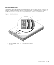
Hard-Drive Indicator Codes The hard-drive carriers have two indicators-the drive-activity indicator and the drive-status indicator. Hard-Drive Indicators 1 2 1 drive-status indicator (green 2 green drive-activity indicator and amber) About Your System 15 See Figure 1-2. In non-RAID configurations, only the drive-activity indicator lights; the drive-status indicator is off. Figure 1-2. In RAID configurations, the drive-status indicator lights to indicate the status of the drive.
Hard-Drive Indicator Codes The hard-drive carriers have two indicators-the drive-activity indicator and the drive-status indicator. Hard-Drive Indicators 1 2 1 drive-status indicator (green 2 green drive-activity indicator and amber) About Your System 15 See Figure 1-2. In non-RAID configurations, only the drive-activity indicator lights; the drive-status indicator is off. Figure 1-2. In RAID configurations, the drive-status indicator lights to indicate the status of the drive.
Hardware Owner's Manual
Page 16
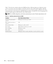
... six seconds. 16 About Your System Blinks green slowly. After the drive is installed, the "drive being prepared for removal" pattern appears, followed by the "drive ready for operation" pattern appears, followed by the "drive online" pattern. The drive-status indicator is active. Hard-Drive Indicator Patterns for RAID Condition Identify drive/preparing for removal Drive ready for RAID hard drives.
... six seconds. 16 About Your System Blinks green slowly. After the drive is installed, the "drive being prepared for removal" pattern appears, followed by the "drive ready for operation" pattern appears, followed by the "drive online" pattern. The drive-status indicator is active. Hard-Drive Indicator Patterns for RAID Condition Identify drive/preparing for removal Drive ready for RAID hard drives.
Hardware Owner's Manual
Page 25
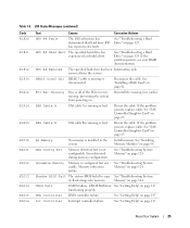
...E2013 E2014 E2015 E2016 Text Causes Corrective Actions HDD ## Fault The SAS subsystem has determined that hard drive ## has experienced a fault. HDD ## Rbld Abrt The specified hard drive has experienced a rebuild abort. If the problem persists, see your RAID documentation. Reconnect the ...on page 124. removed from powering on. See "Troubleshooting System Memory" on page 124. functioning properly. See "Troubleshooting a Hard Drive" on page 65. Reseat the cable. Shadow BIOS Fail The system BIOS failed to copy See "Troubleshooting System its flash ...
...E2013 E2014 E2015 E2016 Text Causes Corrective Actions HDD ## Fault The SAS subsystem has determined that hard drive ## has experienced a fault. HDD ## Rbld Abrt The specified hard drive has experienced a rebuild abort. If the problem persists, see your RAID documentation. Reconnect the ...on page 124. removed from powering on. See "Troubleshooting System Memory" on page 124. functioning properly. See "Troubleshooting a Hard Drive" on page 65. Reseat the cable. Shadow BIOS Fail The system BIOS failed to copy See "Troubleshooting System its flash ...
Hardware Owner's Manual
Page 31
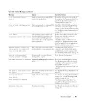
... persists, see "Troubleshooting Expansion Cards" on page 147." Table 1-7. faulty or improperly installed expansion card(s). Use a bootable diskette, CD, or hard drive. Check the hard-drive configuration settings in manufacturing mode. See your hard drive. Ensure that all appropriate cables are securely connected to expansion card(s) loose; Reboot to install PCIe device BIOS (Option ROM) checksum...
... persists, see "Troubleshooting Expansion Cards" on page 147." Table 1-7. faulty or improperly installed expansion card(s). Use a bootable diskette, CD, or hard drive. Check the hard-drive configuration settings in manufacturing mode. See your hard drive. Ensure that all appropriate cables are securely connected to expansion card(s) loose; Reboot to install PCIe device BIOS (Option ROM) checksum...
Hardware Owner's Manual
Page 33
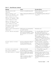
...properly connected. Remote configuration update attempt failed System unable to the expansion card(s). Ensure faulty. Sector not found from the diskette or hard drive, the system could not find a particular sector on page 132. About Your System 33 See "Expansion Cards" on page 124...the specified slot. Read fault The operating system cannot read Requested sector not found Seek error Seek operation failed Faulty diskette or hard drive. ROM bad checksum = address Expansion card improperly installed or Reseat the expansion card(s). page 129. Shutdown failure Shutdown test failure...
...properly connected. Remote configuration update attempt failed System unable to the expansion card(s). Ensure faulty. Sector not found from the diskette or hard drive, the system could not find a particular sector on page 132. About Your System 33 See "Expansion Cards" on page 124...the specified slot. Read fault The operating system cannot read Requested sector not found Seek error Seek operation failed Faulty diskette or hard drive. ROM bad checksum = address Expansion card improperly installed or Reseat the expansion card(s). page 129. Shutdown failure Shutdown test failure...
Hardware Owner's Manual
Page 34
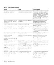
... system. Check both DIMMs for any faulty components specified in "Troubleshooting Your System" on page 115 for a possible fault. See "Getting Help" on the boot hard drive. Create a utility partition on page 147. DIMMs are disabled: DIMM n1 n2 Total memory size is not supported by the n1 and n2. See the... "Troubleshooting System Memory" on page 98. Please check the system event log! See "Installing a Processor" on page 124. See "Troubleshooting System Memory" on the boot hard drive.
... system. Check both DIMMs for any faulty components specified in "Troubleshooting Your System" on page 115 for a possible fault. See "Getting Help" on the boot hard drive. Create a utility partition on page 147. DIMMs are disabled: DIMM n1 n2 Total memory size is not supported by the n1 and n2. See the... "Troubleshooting System Memory" on page 98. Please check the system event log! See "Installing a Processor" on page 124. See "Troubleshooting System Memory" on the boot hard drive.
Hardware Owner's Manual
Page 35
...that section for processor n Micro code update failed. See "Troubleshooting a Diskette Drive" on page 126, "Troubleshooting an Optical Drive" on page 127, and "Troubleshooting a Hard Drive" on page 124. Warning Messages A warning message alerts you to a ...About Your System 35 Warning: One or more information, see "Troubleshooting System Memory" on selected drive Faulty diskette, optical/diskette drive assembly, hard drive, or hard-drive subsystem. No micro code update loaded for obtaining technical assistance. See "General Memory Module Installation Guidelines...
...that section for processor n Micro code update failed. See "Troubleshooting a Diskette Drive" on page 126, "Troubleshooting an Optical Drive" on page 127, and "Troubleshooting a Hard Drive" on page 124. Warning Messages A warning message alerts you to a ...About Your System 35 Warning: One or more information, see "Troubleshooting System Memory" on selected drive Faulty diskette, optical/diskette drive assembly, hard drive, or hard-drive subsystem. No micro code update loaded for obtaining technical assistance. See "General Memory Module Installation Guidelines...
Hardware Owner's Manual
Page 40
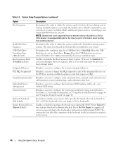
... baud rate, remote terminal type, and redirection after a 30-second timeout if the previous boot attempt failed. See support.dell.com for a USB flash drive. Displays a screen to configure the front-panel LCD options and to a SAS or SCSI adapter. Displays a screen to... keyboard is not supported from external devices Determines the order in which the system searches the hard drives during system startup. Table 2-2. Available options can include the diskette drive, CD drive, hard drives, and network. Displays a screen to the system. 40 Using the System Setup Program See ...
... baud rate, remote terminal type, and redirection after a 30-second timeout if the previous boot attempt failed. See support.dell.com for a USB flash drive. Displays a screen to configure the front-panel LCD options and to a SAS or SCSI adapter. Displays a screen to... keyboard is not supported from external devices Determines the order in which the system searches the hard drives during system startup. Table 2-2. Available options can include the diskette drive, CD drive, hard drives, and network. Displays a screen to the system. 40 Using the System Setup Program See ...
Hardware Owner's Manual
Page 51
Installing System Components This section describes how to install the following system components: • Hard drives • Power supplies • System fans • SAS controller daughter card • RAID battery • Internal USB memory key connector •... Expansion cards • Expansion card cage • Cooling shroud • Fan bracket • RAC card • Optical, diskette, and tape drives • System memory • Processors • System battery • Expansion-card riser boards • Sideplane board • SAS/SATA Backplane board •...
Installing System Components This section describes how to install the following system components: • Hard drives • Power supplies • System fans • SAS controller daughter card • RAID battery • Internal USB memory key connector •... Expansion cards • Expansion card cage • Cooling shroud • Fan bracket • RAC card • Optical, diskette, and tape drives • System memory • Processors • System battery • Expansion-card riser boards • Sideplane board • SAS/SATA Backplane board •...


