
Microprocessor Installation Information
Page 1
...® Processor 5300 series. See "Using the System Setup Program" in the Hardware Owner's Manual included on the CDs provided with your system or on support.dell.com. 2 Check the latest system BIOS version available on support.dell.com. 3 Download and flash the latest BIOS version ...Other trademarks and trade names may be performed by trained service technicians. Dell Inc. All rights reserved. NOTICE: Failure to update your system BIOS version in the System Setup program. See www.dell.com and support.dell.com for information on the CDs provided with a "II," your ...
...® Processor 5300 series. See "Using the System Setup Program" in the Hardware Owner's Manual included on the CDs provided with your system or on support.dell.com. 2 Check the latest system BIOS version available on support.dell.com. 3 Download and flash the latest BIOS version ...Other trademarks and trade names may be performed by trained service technicians. Dell Inc. All rights reserved. NOTICE: Failure to update your system BIOS version in the System Setup program. See www.dell.com and support.dell.com for information on the CDs provided with a "II," your ...
Trusted Platform Module (TPM) Update
Page 1
...subject to either the entities claiming the marks and names or their products. November 2007 disclaims any manner whatsoever without notice. © 2007 Dell Inc. Trusted Platform Module (TPM) Update Systems that are shipping in trademarks and trade names other than its own. All rights reserved. ...Information in this document is strictly forbidden. Trademarks used in the "Using the System Setup Program" chapter of Dell Inc. Reproduction in any proprietary interest in China are trademarks of your Hardware Owner's Manual...
...subject to either the entities claiming the marks and names or their products. November 2007 disclaims any manner whatsoever without notice. © 2007 Dell Inc. Trusted Platform Module (TPM) Update Systems that are shipping in trademarks and trade names other than its own. All rights reserved. ...Information in this document is strictly forbidden. Trademarks used in the "Using the System Setup Program" chapter of Dell Inc. Reproduction in any proprietary interest in China are trademarks of your Hardware Owner's Manual...
Information Update
Page 4
Incorrect Processor Information 23 System Support for Microsoft Windows 2000 . . . 24 System Diagnostics Update 24 4 Contents System Setup Program Update 19 Memory Screen 19 CPU Information Screen 20 Integrated Devices Screen 20 System Security Screen 21 Serial Communication Screen 23 Operating System Information 23 Enumeration of NICs 23 RHEL -
Incorrect Processor Information 23 System Support for Microsoft Windows 2000 . . . 24 System Diagnostics Update 24 4 Contents System Setup Program Update 19 Memory Screen 19 CPU Information Screen 20 Integrated Devices Screen 20 System Security Screen 21 Serial Communication Screen 23 Operating System Information 23 Enumeration of NICs 23 RHEL -

Information Update
Page 5
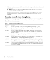
...power conversion across workloads. • Baseboard Management Control (BMC) power monitoring monitors current, voltage, and power utilization in the DIMM set for Setup NOTE: Mixing DIMMs of different speeds renders the memory configuration non-optimal. New System Features New Performance Features • Two dual-core or ... is detected and the following message is displayed: Non-Optimal Memory Configuration Press F1 to the slowest speed in the system. PowerEdge 2950 III - The system clocks down the performance to continue or F2 for the channel. Information Update 5
...power conversion across workloads. • Baseboard Management Control (BMC) power monitoring monitors current, voltage, and power utilization in the DIMM set for Setup NOTE: Mixing DIMMs of different speeds renders the memory configuration non-optimal. New System Features New Performance Features • Two dual-core or ... is detected and the following message is displayed: Non-Optimal Memory Configuration Press F1 to the slowest speed in the system. PowerEdge 2950 III - The system clocks down the performance to continue or F2 for the channel. Information Update 5

Information Update
Page 6
See "Using the System Setup Program" in the System Setup program. For information on creating a bootable file on page 20. To boot from the USB memory key, you must be used as a boot device, security ... connector located on the sideplane board for iSCSI boot. New I/O and Storage Features • Optional Intel quad-port Gigabit Ethernet NIC, capable of the System Setup program.
See "Using the System Setup Program" in the System Setup program. For information on creating a bootable file on page 20. To boot from the USB memory key, you must be used as a boot device, security ... connector located on the sideplane board for iSCSI boot. New I/O and Storage Features • Optional Intel quad-port Gigabit Ethernet NIC, capable of the System Setup program.
Information Update
Page 7
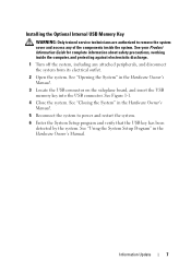
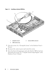
See "Using the System Setup Program" in the Hardware Owner's Manual. 3 Locate the USB connector on the sideplane board, and insert the USB memory key into the USB connector. See ".... Information Update 7 Installing the Optional Internal USB Memory Key WARNING: Only trained service technicians are authorized to power and restart the system. 6 Enter the System Setup program and verify that the USB key has been detected by the system. See your Product Information Guide for complete information about safety precautions, working...
See "Using the System Setup Program" in the Hardware Owner's Manual. 3 Locate the USB connector on the sideplane board, and insert the USB memory key into the USB connector. See ".... Information Update 7 Installing the Optional Internal USB Memory Key WARNING: Only trained service technicians are authorized to power and restart the system. 6 Enter the System Setup program and verify that the USB key has been detected by the system. See your Product Information Guide for complete information about safety precautions, working...
Information Update
Page 8
Installing an Internal USB Key 3 2 1 1 sideplane board 3 USB memory key 2 internal USB connector 7 Close the system. Figure 1-1. See "Using the System Setup Program" in the Hardware Owner's Manual. 8 Reconnect the system to power and restart the system. 9 Enter the System Setup program and verify that the USB key has been detected by the system. See "Closing the System" in the Hardware Owner's Manual. 8 Information Update
Installing an Internal USB Key 3 2 1 1 sideplane board 3 USB memory key 2 internal USB connector 7 Close the system. Figure 1-1. See "Using the System Setup Program" in the Hardware Owner's Manual. 8 Reconnect the system to power and restart the system. 9 Enter the System Setup program and verify that the USB key has been detected by the system. See "Closing the System" in the Hardware Owner's Manual. 8 Information Update
Information Update
Page 10
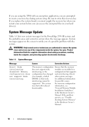
... information about safety precautions, working inside the system. supported. System Message Update Table 1-1 lists new system messages for the PowerEdge 2950 III system and the probable cause and corrective action when the message appears. Table 1-1. The memory configuration Ensure that supports ...you of the components inside the computer, and protecting against electrostatic discharge. Be sure to create a recovery key during system setup. WARNING: Only trained service technicians are installed in a interleaving, or the configuration that the memory does not support node modules...
... information about safety precautions, working inside the system. supported. System Message Update Table 1-1 lists new system messages for the PowerEdge 2950 III system and the probable cause and corrective action when the message appears. Table 1-1. The memory configuration Ensure that supports ...you of the components inside the computer, and protecting against electrostatic discharge. Be sure to create a recovery key during system setup. WARNING: Only trained service technicians are installed in a interleaving, or the configuration that the memory does not support node modules...
Information Update
Page 11
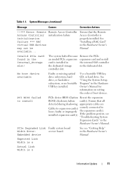
...(s). installed expansion card(s). Expected Link Width is n Actual Link Width is properly installed. Use a bootable USB key, CD, or hard drive. See "Using the System Setup Program" in the Hardware Owner's Manual. If the problem persists, see "Getting Help" in the Hardware Owner's Manual. Embedded device See see "Troubleshooting System Expansion...
...(s). installed expansion card(s). Expected Link Width is n Actual Link Width is properly installed. Use a bootable USB key, CD, or hard drive. See "Using the System Setup Program" in the Hardware Owner's Manual. If the problem persists, see "Getting Help" in the Hardware Owner's Manual. Embedded device See see "Troubleshooting System Expansion...
Information Update
Page 15
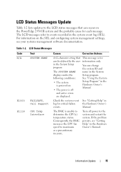
This message is off power to the LCD status messages that can change the system ID and name in the System Setup program. See "Getting Help" in the Hardware Owner's Manual. If the problem persists, see your systems management software documentation. Information Update 15 The LCD messages ... updates to the system and restart the system. Consequently, the BMC increases the CPU fan speed to maximum as a precautionary measure. For information on the PowerEdge 2950 III system and the probable cause for critical failure events. Check the system event log for each message.
This message is off power to the LCD status messages that can change the system ID and name in the System Setup program. See "Getting Help" in the Hardware Owner's Manual. If the problem persists, see your systems management software documentation. Information Update 15 The LCD messages ... updates to the system and restart the system. Consequently, the BMC increases the CPU fan speed to maximum as a precautionary measure. For information on the PowerEdge 2950 III system and the probable cause for critical failure events. Check the system event log for each message.

Information Update
Page 19
... set to Disabled, the memory runs at system boot. When set to Spare Mode, the first rank of memory on the Memory Information screen. System Setup Program Update Memory Screen Table 1-3 lists the descriptions for the information fields that appear on each DIMM is reserved for memory sparing. Options are run...
... set to Disabled, the memory runs at system boot. When set to Spare Mode, the first rank of memory on the Memory Information screen. System Setup Program Update Memory Screen Table 1-3 lists the descriptions for the information fields that appear on each DIMM is reserved for memory sparing. Options are run...

Information Update
Page 29
POST Non-Optimal Memory Configuration Press F1 to continue or F2 for Setup (按 F1 F2 DIMM DIMM PowerEdge 2950 III 全新性能 Intel® Xeon® 5400 系列和 5300 8 GB BMC 信息更新 29
POST Non-Optimal Memory Configuration Press F1 to continue or F2 for Setup (按 F1 F2 DIMM DIMM PowerEdge 2950 III 全新性能 Intel® Xeon® 5400 系列和 5300 8 GB BMC 信息更新 29

Information Update
Page 109
POST Non-Optimal Memory Configuration Press F1 to continue or F2 for Setup F1 F2 DIMM DIMM DIMM PowerEdge 2950 III Intel® Xeon® 5400 5300 2 個。 • 8 GB BMC 109
POST Non-Optimal Memory Configuration Press F1 to continue or F2 for Setup F1 F2 DIMM DIMM DIMM PowerEdge 2950 III Intel® Xeon® 5400 5300 2 個。 • 8 GB BMC 109

Information Update
Page 137
POST Non-Optimal Memory Configuration Press F1 to continue or F2 for Setup F1 F2 DIMM DIMM PowerEdge 2950 III Intel® Xeon® 5400 5300 • 8GB BMC 137
POST Non-Optimal Memory Configuration Press F1 to continue or F2 for Setup F1 F2 DIMM DIMM PowerEdge 2950 III Intel® Xeon® 5400 5300 • 8GB BMC 137

Information Update
Page 143
표 1-1 메시지 원인 No boot device available USB 키 , CD USB System Setup PCI BIOS failed to install PCIe BIOS( 옵션 ROM PCIe Degraded Link Width Error: Embedded device Expected Link Width is n Actual Link Width is n PCIe Degraded Link Width Error: Integrated device Expected Link Width is n Actual Link Width is n 특정 PCIe SAS PCIe SAS 143
표 1-1 메시지 원인 No boot device available USB 키 , CD USB System Setup PCI BIOS failed to install PCIe BIOS( 옵션 ROM PCIe Degraded Link Width Error: Embedded device Expected Link Width is n Actual Link Width is n PCIe Degraded Link Width Error: Integrated device Expected Link Width is n Actual Link Width is n 특정 PCIe SAS PCIe SAS 143

Getting Started Guide
Page 11
To install an operating system for the first time, see the operating system documentation that ships with the system. Installing the Bezel Install the bezel (optional). Complete the 0perating System Setup If you purchased a preinstalled operating system, see the Quick Installation Guide. Be sure the operating system is installed before installing hardware or software not purchased with your system. Getting Started With Your System 9
To install an operating system for the first time, see the operating system documentation that ships with the system. Installing the Bezel Install the bezel (optional). Complete the 0perating System Setup If you purchased a preinstalled operating system, see the Quick Installation Guide. Be sure the operating system is installed before installing hardware or software not purchased with your system. Getting Started With Your System 9
Hardware Owner's Manual (PDF)
Page 3
... 27 System Messages 28 Warning Messages 35 Diagnostics Messages 35 Alert Messages 35 2 Using the System Setup Program 37 Entering the System Setup Program 37 Responding to Error Messages 37 Using the System Setup Program 38 System Setup Options 38 Main Screen 38 CPU Information Screen 41 Integrated Devices Screen 42 Serial Communication Screen...
... 27 System Messages 28 Warning Messages 35 Diagnostics Messages 35 Alert Messages 35 2 Using the System Setup Program 37 Entering the System Setup Program 37 Responding to Error Messages 37 Using the System Setup Program 38 System Setup Options 38 Main Screen 38 CPU Information Screen 41 Integrated Devices Screen 42 Serial Communication Screen...
Hardware Owner's Manual (PDF)
Page 4
... 47 Disabling a Forgotten Password 48 Baseboard Management Controller Configuration 48 Entering the BMC Setup Module 49 BMC Setup Module Options 49 3 Installing System Components 51 Recommended Tools 51 Inside the System 52 Front Bezel 53 Removing the Front Bezel 53 Replacing the Front ...
... 47 Disabling a Forgotten Password 48 Baseboard Management Controller Configuration 48 Entering the BMC Setup Module 49 BMC Setup Module Options 49 3 Installing System Components 51 Recommended Tools 51 Inside the System 52 Front Bezel 53 Removing the Front Bezel 53 Replacing the Front ...
Hardware Owner's Manual (PDF)
Page 12
... users or technicians. If your operating system begins to load before you have the optional Dell Remote Access Controller (DRAC), this keystroke allows access to configure NIC settings for more information on setup and use of BMC. See the BMC User's Guide for PXE boot. See the ... the Baseboard Management Controller (BMC) Management Utility, which allows you to the system event log (SEL). See "Using the System Setup Program" on support.dell.com and read the updates first because they often supersede information in other documents. • Release notes or readme files may be...
... users or technicians. If your operating system begins to load before you have the optional Dell Remote Access Controller (DRAC), this keystroke allows access to configure NIC settings for more information on setup and use of BMC. See the BMC User's Guide for PXE boot. See the ... the Baseboard Management Controller (BMC) Management Utility, which allows you to the system event log (SEL). See "Using the System Setup Program" on support.dell.com and read the updates first because they often supersede information in other documents. • Release notes or readme files may be...

Hardware Owner's Manual (PDF)
Page 17
... information about enabling, disabling, and configuring I/O ports and connectors, see "Jumpers and Connectors" on page 37. For information about individual connectors, see "Using the System Setup Program" on page 135. Figure 1-3. Back-Panel Features and Indicators Figure 1-3 shows the controls, indicators, and connectors located on any external devices before the device...
... information about enabling, disabling, and configuring I/O ports and connectors, see "Jumpers and Connectors" on page 37. For information about individual connectors, see "Using the System Setup Program" on page 135. Figure 1-3. Back-Panel Features and Indicators Figure 1-3 shows the controls, indicators, and connectors located on any external devices before the device...


