
Information Update
Page 10
...supply the recovery key when you restart your system before you are prompted to remove the system cover and access any of the hard drive. If you are authorized to create a recovery key during system setup. System Message Update Table 1-1 lists new system messages for ...you can access the encrypted files on your Product Information Guide for the PowerEdge 1950 III system and the probable cause and corrective action when the message appears. See your hard drive(s). Safeguarding Encrypted Data On PowerEdge 1950 III systems using the TPM with an encryption application, you can use ...
...supply the recovery key when you restart your system before you are prompted to remove the system cover and access any of the hard drive. If you are authorized to create a recovery key during system setup. System Message Update Table 1-1 lists new system messages for ...you can access the encrypted files on your Product Information Guide for the PowerEdge 1950 III system and the probable cause and corrective action when the message appears. See your hard drive(s). Safeguarding Encrypted Data On PowerEdge 1950 III systems using the TPM with an encryption application, you can use ...
Information Update
Page 11
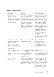
...Module Installation Guidelines" in the Internal_Storage slot! No boot device available Faulty or missing optical drive subsystem, hard drive, or hard-drive subsystem, or no bootable USB key installed. Ensure that the Remote Access Controller is installed ... Controller initialization failure *** RAC virtual USB devices may not be for possible causes. For supported. Use a bootable USB key, CD, or hard drive. Information Update 11 If the problem persists, see "General functionality. Invalid PCIe card found in the Hardware Owner's Manual. controller slot. Check...
...Module Installation Guidelines" in the Internal_Storage slot! No boot device available Faulty or missing optical drive subsystem, hard drive, or hard-drive subsystem, or no bootable USB key installed. Ensure that the Remote Access Controller is installed ... Controller initialization failure *** RAC virtual USB devices may not be for possible causes. For supported. Use a bootable USB key, CD, or hard drive. Information Update 11 If the problem persists, see "General functionality. Invalid PCIe card found in the Hardware Owner's Manual. controller slot. Check...
Information Update
Page 15
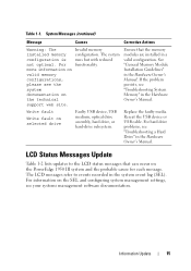
... or USB cable. For more information on valid memory configurations, please see "Troubleshooting a Hard Drive" in the Hardware Owner's Manual. See "General Memory Module Installation Guidelines" in the Hardware Owner's Manual. For hard drive problems, see the system documentation on the PowerEdge 1950 III system and the probable cause for each message. Replace the faulty media...
... or USB cable. For more information on valid memory configurations, please see "Troubleshooting a Hard Drive" in the Hardware Owner's Manual. See "General Memory Module Installation Guidelines" in the Hardware Owner's Manual. For hard drive problems, see the system documentation on the PowerEdge 1950 III system and the probable cause for each message. Replace the faulty media...

Information Update
Page 26
System Diagnostics Custom Test Options In the Customize window of the system diagnostics, the Log output file pathname option enables you to a hard drive. 26 Information Update You cannot save the file to specify the diskette drive or USB memory key where the test log file is saved. Hardware Owner's Manual Updates Installing the Processor When installing the processor, the processor shield must be closed before securing the processor with the socket release lever.
System Diagnostics Custom Test Options In the Customize window of the system diagnostics, the Log output file pathname option enables you to a hard drive. 26 Information Update You cannot save the file to specify the diskette drive or USB memory key where the test log file is saved. Hardware Owner's Manual Updates Installing the Processor When installing the processor, the processor shield must be closed before securing the processor with the socket release lever.

Hardware Owner's Manual (PDF)
Page 3
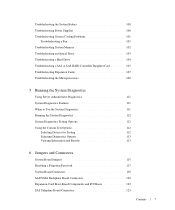
Contents 1 About Your System Other Information You May Need 9 Accessing System Features During Startup 10 Front-Panel Features and Indicators 11 Hard-Drive Indicator Codes 12 Back-Panel Features and Indicators 14 Connecting External Devices 15 Power Indicator Codes 15 NIC Indicator Codes 16 LCD Status Messages 17 ...
Contents 1 About Your System Other Information You May Need 9 Accessing System Features During Startup 10 Front-Panel Features and Indicators 11 Hard-Drive Indicator Codes 12 Back-Panel Features and Indicators 14 Connecting External Devices 15 Power Indicator Codes 15 NIC Indicator Codes 16 LCD Status Messages 17 ...

Hardware Owner's Manual (PDF)
Page 5
... Card 62 Configuring the Boot Device 63 Configuring the Boot Drive 63 System Memory 63 General Memory Module Installation Guidelines 64...Drive Tray 73 Installing the Optical Drive Tray 74 Hard Drives 75 Before You Begin 75 Removing a Drive Blank 75 Installing a Drive Blank 76 Installing a Hot-Plug Hard Drive 76 Replacing a Hard-Drive Carrier 78 Removing a Hard Drive From a Hard-Drive Carrier 78 Installing a SAS Hard Drive Into a SATAu Drive Carrier 78 Installing a SATA Hard Drive Into a SATA Drive Carrier 79 Installing a SATA Hard Drive and Interposer Card Into a SATAu Hard-Drive...
... Card 62 Configuring the Boot Device 63 Configuring the Boot Drive 63 System Memory 63 General Memory Module Installation Guidelines 64...Drive Tray 73 Installing the Optical Drive Tray 74 Hard Drives 75 Before You Begin 75 Removing a Drive Blank 75 Installing a Drive Blank 76 Installing a Hot-Plug Hard Drive 76 Replacing a Hard-Drive Carrier 78 Removing a Hard Drive From a Hard-Drive Carrier 78 Installing a SAS Hard Drive Into a SATAu Drive Carrier 78 Installing a SATA Hard Drive Into a SATA Drive Carrier 79 Installing a SATA Hard Drive and Interposer Card Into a SATAu Hard-Drive...
Hardware Owner's Manual (PDF)
Page 7
Troubleshooting the System Battery 100 Troubleshooting Power Supplies 100 Troubleshooting System Cooling Problems 101 Troubleshooting a Fan 101 Troubleshooting System Memory 102 Troubleshooting an Optical Drive 103 Troubleshooting a Hard Drive 104 Troubleshooting a SAS or SAS RAID Controller Daughter Card 105 Troubleshooting Expansion Cards 107 Troubleshooting the Microprocessors 108 5 Running the System Diagnostics Using Server Administrator...
Troubleshooting the System Battery 100 Troubleshooting Power Supplies 100 Troubleshooting System Cooling Problems 101 Troubleshooting a Fan 101 Troubleshooting System Memory 102 Troubleshooting an Optical Drive 103 Troubleshooting a Hard Drive 104 Troubleshooting a SAS or SAS RAID Controller Daughter Card 105 Troubleshooting Expansion Cards 107 Troubleshooting the Microprocessors 108 5 Running the System Diagnostics Using Server Administrator...
Hardware Owner's Manual (PDF)
Page 12
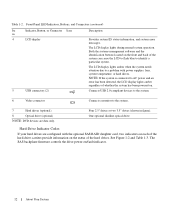
... connector Connects a monitor to a problem with the optional SAS RAID daughter card, two indicators on each of the hard drives. Both the systems management software and the identification buttons located on . The LCD display lights amber when the system...due to the system. 7 Hard drives (optional) 8 Optical drive (optional) NOTE: DVD devices are configured with power supplies, fans, system temperature, or hard drives. One optional slimline optical drive Hard-Drive Indicator Codes If your hard drives are data only. Four 2.5" drives or two 3.5" drives (shown in figure). Front...
... connector Connects a monitor to a problem with the optional SAS RAID daughter card, two indicators on each of the hard drives. Both the systems management software and the identification buttons located on . The LCD display lights amber when the system...due to the system. 7 Hard drives (optional) 8 Optical drive (optional) NOTE: DVD devices are configured with power supplies, fans, system temperature, or hard drives. One optional slimline optical drive Hard-Drive Indicator Codes If your hard drives are data only. Four 2.5" drives or two 3.5" drives (shown in figure). Front...

Hardware Owner's Manual (PDF)
Page 13
... active. NOTE: For non-RAID configurations, only the drive-activity indicator is off. Different patterns are displayed as drive events occur in the system. For example, if a hard-drive fails, the "drive failed" pattern appears. Hard-Drive Indicators 1 2 1 drive-status indicator (green 2 green drive-activity indicator and amber) Table 1-3 lists the drive indicator patterns. About Your System 13 After the...
... active. NOTE: For non-RAID configurations, only the drive-activity indicator is off. Different patterns are displayed as drive events occur in the system. For example, if a hard-drive fails, the "drive failed" pattern appears. Hard-Drive Indicators 1 2 1 drive-status indicator (green 2 green drive-activity indicator and amber) Table 1-3 lists the drive indicator patterns. About Your System 13 After the...

Hardware Owner's Manual (PDF)
Page 14
... connector 9 system status indicator 12 left PCI expansion slot (slot 2) 14 About Your System Hard-Drive Indicator Patterns for RAID Condition Identify drive/preparing for removal Drive ready for insertion or removal Drive predicted failure Drive failed Drive rebuilding Drive online Rebuild aborted Drive-Status Indicator Pattern Blinks green two times per second. Back-Panel Features and Indicators Figure...
... connector 9 system status indicator 12 left PCI expansion slot (slot 2) 14 About Your System Hard-Drive Indicator Patterns for RAID Condition Identify drive/preparing for removal Drive ready for insertion or removal Drive predicted failure Drive failed Drive rebuilding Drive online Rebuild aborted Drive-Status Indicator Pattern Blinks green two times per second. Back-Panel Features and Indicators Figure...
Hardware Owner's Manual (PDF)
Page 20
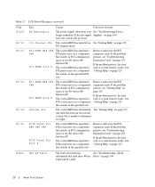
... BIOS has reported a PCIe fatal error on page 104. Remove and reseat the PCI expansion cards. E1810 HDD ## Fault The SAS subsystem has See "Troubleshooting a Hard determined that hard drive ## has Drive" on a component that resides in the specified slot.
... BIOS has reported a PCIe fatal error on page 104. Remove and reseat the PCI expansion cards. E1810 HDD ## Fault The SAS subsystem has See "Troubleshooting a Hard determined that hard drive ## has Drive" on a component that resides in the specified slot.

Hardware Owner's Manual (PDF)
Page 21
...E2012 E2013 E2014 E2015 Text Causes Corrective Actions HDD ## Rbld Abrt The specified hard drive has experienced a rebuild abort. If the problem persists, see your RAID documentation. HDD ## Removed The specified hard drive has been Information only. See the BMC User's Guide for more information on... CMOS failure. Reseat the cable. See "Troubleshooting System Memory" on page 102. Memory" on page 102. Table 1-7. See "Troubleshooting a Hard Drive" on page 125. If the problem bad. Pwr Cable FB Flex bay power cable is missing or Reseat the cable. See "Getting Help...
...E2012 E2013 E2014 E2015 Text Causes Corrective Actions HDD ## Rbld Abrt The specified hard drive has experienced a rebuild abort. If the problem persists, see your RAID documentation. HDD ## Removed The specified hard drive has been Information only. See the BMC User's Guide for more information on... CMOS failure. Reseat the cable. See "Troubleshooting System Memory" on page 102. Memory" on page 102. Table 1-7. See "Troubleshooting a Hard Drive" on page 125. If the problem bad. Pwr Cable FB Flex bay power cable is missing or Reseat the cable. See "Getting Help...
Hardware Owner's Manual (PDF)
Page 27
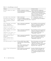
...See "Getting Help" on page 102. MEMBIST failure - on page 125. Use a CD or hard drive. If the problem persists, see "Troubleshooting an Optical Drive" on page 103 and "Troubleshooting a Hard Drive" on setting the order of manufacturing mode. About Your System 27 pressing the spacebar. No boot... device available Faulty or missing optical drive subsystem, hard drive, or hard-drive subsystem, or no boot disk in manufacturing mode. See "Using the System Setup Program" on page 31 for information ...
...See "Getting Help" on page 102. MEMBIST failure - on page 125. Use a CD or hard drive. If the problem persists, see "Troubleshooting an Optical Drive" on page 103 and "Troubleshooting a Hard Drive" on setting the order of manufacturing mode. About Your System 27 pressing the spacebar. No boot... device available Faulty or missing optical drive subsystem, hard drive, or hard-drive subsystem, or no boot disk in manufacturing mode. See "Using the System Setup Program" on page 31 for information ...
Hardware Owner's Manual (PDF)
Page 28
...PCIe card in initializing PCI Error device; Reseat the PCIe card in the specified slot number. See "Expansion-Card Riser" on hard drive No timer tick interrupt Northbound merge error The following DIMM has been disabled by BIOS: DIMM x Causes Corrective Actions Incorrect configuration ... Error: Embedded Bus#nn/Dev#nn/Funcn Faulty or improperly installed PCIe card in the specified slot. See "Expansion-Card Riser" on hard drive. Ensure that all appropriate cables are securely connected to install PCI device BIOS (Option ROM) checksum failure is n PCIe Degraded Link Width...
...PCIe card in initializing PCI Error device; Reseat the PCIe card in the specified slot number. See "Expansion-Card Riser" on hard drive No timer tick interrupt Northbound merge error The following DIMM has been disabled by BIOS: DIMM x Causes Corrective Actions Incorrect configuration ... Error: Embedded Bus#nn/Dev#nn/Funcn Faulty or improperly installed PCIe card in the specified slot. See "Expansion-Card Riser" on hard drive. Ensure that all appropriate cables are securely connected to install PCI device BIOS (Option ROM) checksum failure is n PCIe Degraded Link Width...
Hardware Owner's Manual (PDF)
Page 29
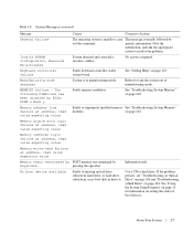
.... See "Troubleshooting System Memory" on page 107, or defective. "Troubleshooting a Hard Drive" on page 104 for the appropriate drive(s) installed in your system. Ensure that only Dell-qualified memory is informative and can be faulty. See "Troubleshooting a Hard Drive" on page 104 for the appropriate drive(s) installed in your system. See "Troubleshooting the System Battery" on the...
.... See "Troubleshooting System Memory" on page 107, or defective. "Troubleshooting a Hard Drive" on page 104 for the appropriate drive(s) installed in your system. Ensure that only Dell-qualified memory is informative and can be faulty. See "Troubleshooting a Hard Drive" on page 104 for the appropriate drive(s) installed in your system. See "Troubleshooting the System Battery" on the...
Hardware Owner's Manual (PDF)
Page 30
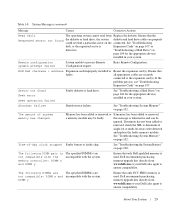
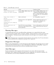
...in that accompanied the operating system or application. Alert messages include information, status, warning, and failure messages for your the boot hard drive. See system battery. See the CDs that you run SETUP program Timer chip counter 2 failed Unsupported CPU combination Unsupported CPU ... If the problem persists, replace the system battery. microprocessor combination. The key was pressed during Create a utility partition on the boot hard POST, but no ). Warning messages usually interrupt the task and require you to respond before you format a diskette, a message will...
...in that accompanied the operating system or application. Alert messages include information, status, warning, and failure messages for your the boot hard drive. See system battery. See the CDs that you run SETUP program Timer chip counter 2 failed Unsupported CPU combination Unsupported CPU ... If the problem persists, replace the system battery. microprocessor combination. The key was pressed during Create a utility partition on the boot hard POST, but no ). Warning messages usually interrupt the task and require you to respond before you format a diskette, a message will...
Hardware Owner's Manual (PDF)
Page 34
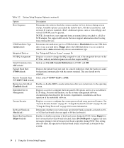
... Rate (57600 default) Displays the failsafe baud rate used for host systems that have installed a RAC, additional options, such as a hard drive. For more information. Serial Communication (Off default) Options are On with the NumLock mode activated on page 40 for the latest support .... Select Do Not Report to suppress all error messages relating to configure the system password and setup password features. See support.dell.com for more information, see the systems management software documentation that require an IRQ. System Security Displays a screen to the ...
... Rate (57600 default) Displays the failsafe baud rate used for host systems that have installed a RAC, additional options, such as a hard drive. For more information. Serial Communication (Off default) Options are On with the NumLock mode activated on page 40 for the latest support .... Select Do Not Report to suppress all error messages relating to configure the system password and setup password features. See support.dell.com for more information, see the systems management software documentation that require an IRQ. System Security Displays a screen to the ...
Hardware Owner's Manual (PDF)
Page 43
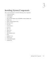
... card or SAS RAID controller daughter card • RAID battery • RAID controller expansion card • Expansion cards • Boot drive • System memory • Processors • RAC card • Optical drive • Hard drives • SAS backplane boards • Risers • Sideplane board • System battery • Control panel assembly • System board...
... card or SAS RAID controller daughter card • RAID battery • RAID controller expansion card • Expansion cards • Boot drive • System memory • Processors • RAC card • Optical drive • Hard drives • SAS backplane boards • Risers • Sideplane board • System battery • Control panel assembly • System board...
Hardware Owner's Manual (PDF)
Page 45
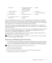
...up to a SAS controller daughter card or a SAS RAID controller daughter card. NOTE: There are installing a hot-plug hard drive, turn off the system and attached peripherals, and disconnect the system from the system. Unless you may be required to ...11 heatsink/microprocessor (2) 12 backplane 1 two 3.5-inch or four 2.5-inch 14 optical slimline drive 3 hard drive bays (optional) The system board holds the system's control circuitry and other electronic components. The optical drive tray connects to access the internal system components. 1 control panel 2 SAS controller daughter ...
...up to a SAS controller daughter card or a SAS RAID controller daughter card. NOTE: There are installing a hot-plug hard drive, turn off the system and attached peripherals, and disconnect the system from the system. Unless you may be required to ...11 heatsink/microprocessor (2) 12 backplane 1 two 3.5-inch or four 2.5-inch 14 optical slimline drive 3 hard drive bays (optional) The system board holds the system's control circuitry and other electronic components. The optical drive tray connects to access the internal system components. 1 control panel 2 SAS controller daughter ...
Hardware Owner's Manual (PDF)
Page 56
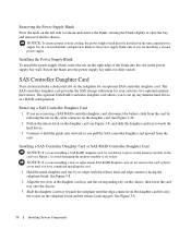
... edge of the blank into the socket on the chassis, then lower the card tray onto the chassis. 3 Slide the daughter card tray towards the hard drives. 3 Continue to hold the guide rails outward as you are removing a SAS RAID controller daughter card, disconnect the battery cable from the card by ...a SAS RAID daughter card, be installed on the left side to release and remove the blank, rotating the blank slightly to set up any internal hard drives in the daughter card tray and the corresponding tabs on the sideplane board and the release latch engages. to press on the memory module on...
... edge of the blank into the socket on the chassis, then lower the card tray onto the chassis. 3 Slide the daughter card tray towards the hard drives. 3 Continue to hold the guide rails outward as you are removing a SAS RAID controller daughter card, disconnect the battery cable from the card by ...a SAS RAID daughter card, be installed on the left side to release and remove the blank, rotating the blank slightly to set up any internal hard drives in the daughter card tray and the corresponding tabs on the sideplane board and the release latch engages. to press on the memory module on...


