

Getting Started Guide
Page 5
...modules in an expansion-card cage. PCIe slots accommodate up to x8 expansion cards. NOTE: If you must order the processor upgrade kits from Dell contains the correct version of the processor and heat sink. • A minimum of 512 MB of 533 or 667 MHz (when available...diskette drive. • An optional CD, DVD, or combination CD-RW/DVD drive. Slot 1 accommodates halflength expansion cards. slot 3 is available on the system board. • Support for up to six 3.5-inch, internal Serial-Attached SCSI (SAS) hard drives or six 3.5-inch, internal SATA hard drives. • Peripheral...
...modules in an expansion-card cage. PCIe slots accommodate up to x8 expansion cards. NOTE: If you must order the processor upgrade kits from Dell contains the correct version of the processor and heat sink. • A minimum of 512 MB of 533 or 667 MHz (when available...diskette drive. • An optional CD, DVD, or combination CD-RW/DVD drive. Slot 1 accommodates halflength expansion cards. slot 3 is available on the system board. • Support for up to six 3.5-inch, internal Serial-Attached SCSI (SAS) hard drives or six 3.5-inch, internal SATA hard drives. • Peripheral...
Hardware Owner's Manual (PDF)
Page 6
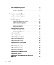
...-Only Procedure 97 Removing the System Board 97 Installing the System Board 99 4 Troubleshooting Your System Safety First-For You and Your System 101 Start-Up Routine 101 Checking the Equipment 102 Troubleshooting IRQ Assignment Conflicts 102 ...
...-Only Procedure 97 Removing the System Board 97 Installing the System Board 99 4 Troubleshooting Your System Safety First-For You and Your System 101 Start-Up Routine 101 Checking the Equipment 102 Troubleshooting IRQ Assignment Conflicts 102 ...
Hardware Owner's Manual (PDF)
Page 7
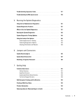
...Selecting Devices for Testing 122 Selecting Diagnostics Options 123 Viewing Information and Results 123 6 Jumpers and Connectors System Board Jumpers 125 System Board Connectors 127 Disabling a Forgotten Password 129 7 Getting Help Technical Assistance 131 Online Services 131 AutoTech Service ...132 Automated Order-Status Service 132 Technical Support Service 132 Dell Enterprise Training and Certification 133 Problems With Your Order ...
...Selecting Devices for Testing 122 Selecting Diagnostics Options 123 Viewing Information and Results 123 6 Jumpers and Connectors System Board Jumpers 125 System Board Connectors 127 Disabling a Forgotten Password 129 7 Getting Help Technical Assistance 131 Online Services 131 AutoTech Service ...132 Automated Order-Status Service 132 Technical Support Service 132 Dell Enterprise Training and Certification 133 Problems With Your Order ...
Hardware Owner's Manual (PDF)
Page 19
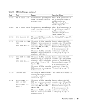
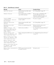
... the problem persists, see "Troubleshooting the Power Supply" on page 117. If the problem persists, the The system BIOS has reported a system board is faulty. PS # Input Range Power source for specified power supply is unavailable, or out of acceptable range. I /O Channel Chk The system...in the system, but is faulty. The system BIOS has reported a PCI parity error on page 131. If the problem persists, the system board is unable to determine its origin. If problem persists, see "Troubleshooting Expansion Cards" on a component that resides in slot #. function ##. ...
... the problem persists, see "Troubleshooting the Power Supply" on page 117. If the problem persists, the The system BIOS has reported a system board is faulty. PS # Input Range Power source for specified power supply is unavailable, or out of acceptable range. I /O Channel Chk The system...in the system, but is faulty. The system BIOS has reported a PCI parity error on page 131. If the problem persists, the system board is unable to determine its origin. If problem persists, see "Troubleshooting Expansion Cards" on a component that resides in slot #. function ##. ...
Hardware Owner's Manual (PDF)
Page 24
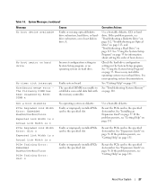
If problem persists, see "Troubleshooting System disabled. board. CPUs with different cache sizes are installed. See "Microprocessor" on page 131. The following DIMM pair is installed. Ensure that all pairs of memory modules ...
If problem persists, see "Troubleshooting System disabled. board. CPUs with different cache sizes are installed. See "Microprocessor" on page 131. The following DIMM pair is installed. Ensure that all pairs of memory modules ...
Hardware Owner's Manual (PDF)
Page 26
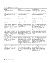
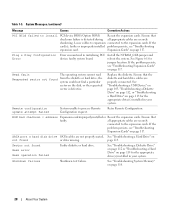
... Actions See "Getting Help" on page 131. Faulty memory module(s). See "Troubleshooting System Memory" on page 110. on page 110. faulty system board. pressing the spacebar. Table 1-5. faulty system board System is unable to resolve the problem. System Messages (continued) Message Gate A20 failure General failure Invalid NVRAM configuration, Resource Re-allocated...
... Actions See "Getting Help" on page 131. Faulty memory module(s). See "Troubleshooting System Memory" on page 110. on page 110. faulty system board. pressing the spacebar. Table 1-5. faulty system board System is unable to resolve the problem. System Messages (continued) Message Gate A20 failure General failure Invalid NVRAM configuration, Resource Re-allocated...
Hardware Owner's Manual (PDF)
Page 27
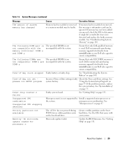
Incorrect configuration settings in System Setup program, or no boot disk in the specified slot number. Faulty system board. Corrective Actions Use a bootable diskette, CD, or hard drive. If the problem persists, see "Getting Help" on diskette. If necessary, install the operating system on ...
Incorrect configuration settings in System Setup program, or no boot disk in the specified slot number. Faulty system board. Corrective Actions Use a bootable diskette, CD, or hard drive. If the problem persists, see "Getting Help" on diskette. If necessary, install the operating system on ...
Hardware Owner's Manual (PDF)
Page 28
... About Your System all appropriate cables are securely connected to install PCI device BIOS (Option ROM) Reseat the expansion cards. If the card(s); faulty system board. See Figure 6-1 for the appropriate drive(s) installed in your system. Shutdown failure Shutdown test failure. Expansion Cards" on page 115 for the appropriate drive(s) installed...
... About Your System all appropriate cables are securely connected to install PCI device BIOS (Option ROM) Reseat the expansion cards. If the card(s); faulty system board. See Figure 6-1 for the appropriate drive(s) installed in your system. Shutdown failure Shutdown test failure. Expansion Cards" on page 115 for the appropriate drive(s) installed...
Hardware Owner's Manual (PDF)
Page 29
...DIMM x and incompatible with the system. See "Troubleshooting the System Battery" on page 110. Timer chip counter 2 failed Faulty system board. See "Microprocessor" on page 33. See the CDs that came with the system. Update the BIOS firmware. If memory has been... detected Microprocessor(s) is used . Warning! No microcode update loaded for processor n Microcode update failed. DIMM y Ensure that only Dell-qualified memory is not supported by Install a supported microprocessor or the system. System Messages (continued) Message Causes Corrective Actions The amount...
...DIMM x and incompatible with the system. See "Troubleshooting the System Battery" on page 110. Timer chip counter 2 failed Faulty system board. See "Microprocessor" on page 33. See the CDs that came with the system. Update the BIOS firmware. If memory has been... detected Microprocessor(s) is used . Warning! No microcode update loaded for processor n Microcode update failed. DIMM y Ensure that only Dell-qualified memory is not supported by Install a supported microprocessor or the system. System Messages (continued) Message Causes Corrective Actions The amount...
Hardware Owner's Manual (PDF)
Page 36
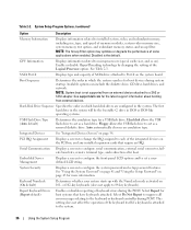
...features. Select Report for a USB flash drive. Available options can include the diskette drive, CD drive, hard drives, and network. See support.dell.com for more information. System Security Displays a screen to set a userdefined LCD string. NOTE: System boot is the default. Hard disk allows... expansion cards that have keyboards attached. See "Using the System Password" on page 41 and "Using the Setup Password" on the system board. This setting does not affect the operation of SATA drive attached to installed system, video, and redundant memory, including size, type, and...
...features. Select Report for a USB flash drive. Available options can include the diskette drive, CD drive, hard drives, and network. See support.dell.com for more information. System Security Displays a screen to set a userdefined LCD string. NOTE: System boot is the default. Hard disk allows... expansion cards that have keyboards attached. See "Using the System Password" on page 41 and "Using the Setup Password" on the system board. This setting does not affect the operation of SATA drive attached to installed system, video, and redundant memory, including size, type, and...
Hardware Owner's Manual (PDF)
Page 41
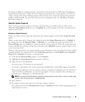
See "Disabling a Forgotten Password" on the system board is in your new system password. Assigning a System Password Before you cannot operate your password, press or the left-arrow key. If the setting shown ...
See "Disabling a Forgotten Password" on the system board is in your new system password. Assigning a System Password Before you cannot operate your password, press or the left-arrow key. If the setting shown ...
Hardware Owner's Manual (PDF)
Page 45
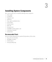
... diskette drives • System battery • System memory • RAC card • Microprocessors • SAS RAID controller daughter card • Control panel assembly • System board Recommended Tools You may need the following items to perform the procedures in this section: • Keys to the system keylocks • #2 Phillips screwdriver •...
... diskette drives • System battery • System memory • RAC card • Microprocessors • SAS RAID controller daughter card • Control panel assembly • System board Recommended Tools You may need the following items to perform the procedures in this section: • Keys to the system keylocks • #2 Phillips screwdriver •...
Hardware Owner's Manual (PDF)
Page 50
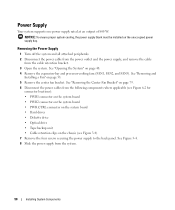
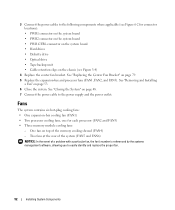
... power supply from the following components where applicable (see Figure 6-2 for connector locations): • PWR1 connector on the system board • PWR2 connector on the system board • PWR CTRL connector on the system board • Hard drives • Diskette drive • Optical drive • Tape backup unit • Cable retention clips on...
... power supply from the following components where applicable (see Figure 6-2 for connector locations): • PWR1 connector on the system board • PWR2 connector on the system board • PWR CTRL connector on the system board • Hard drives • Diskette drive • Optical drive • Tape backup unit • Cable retention clips on...
Hardware Owner's Manual (PDF)
Page 52
...-bay cooling fan (FAN1) • Two processor cooling fans, one for connector locations): • PWR1 connector on the system board • PWR2 connector on the system board • PWR CTRL connector on the system board • Hard drives • Diskette drive • Optical drive • Tape backup unit • Cable retention clips on...
...-bay cooling fan (FAN1) • Two processor cooling fans, one for connector locations): • PWR1 connector on the system board • PWR2 connector on the system board • PWR CTRL connector on the system board • Hard drives • Diskette drive • Optical drive • Tape backup unit • Cable retention clips on...
Hardware Owner's Manual (PDF)
Page 53
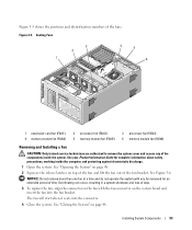
... of the fan bracket. The fan will start when it seats into the fan bracket. Figure 3-5. See Figure 3-6. See "Closing the System" on the system board and insert the fan into the connector. 4 Close the system. NOTICE: Do not remove more than one fan at a time and do not operate the...
... of the fan bracket. The fan will start when it seats into the fan bracket. Figure 3-5. See Figure 3-6. See "Closing the System" on the system board and insert the fan into the connector. 4 Close the system. NOTICE: Do not remove more than one fan at a time and do not operate the...
Hardware Owner's Manual (PDF)
Page 54
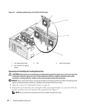
... inside the computer, and protecting against electrostatic discharge. NOTE: Do not remove the cooling shroud from the cooling shroud by squeezing the latches on system board 2 fan 3 center fan bracket Removing and Installing the Cooling Shroud Fan CAUTION: Only trained service technicians are authorized to perform this step. 54 Installing System...
... inside the computer, and protecting against electrostatic discharge. NOTE: Do not remove the cooling shroud from the cooling shroud by squeezing the latches on system board 2 fan 3 center fan bracket Removing and Installing the Cooling Shroud Fan CAUTION: Only trained service technicians are authorized to perform this step. 54 Installing System...
Hardware Owner's Manual (PDF)
Page 59
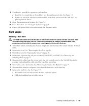
... System" on page 46. 3 Open the system. See "Removing the Center Fan Bracket" on page 79. 7 Disconnect the interface and power cables from the system board, the SAS controller card, or the SAS RAID controller daughter card, and pull the cable out of the way of the components inside the system...
... System" on page 46. 3 Open the system. See "Removing the Center Fan Bracket" on page 79. 7 Disconnect the interface and power cables from the system board, the SAS controller card, or the SAS RAID controller daughter card, and pull the cable out of the way of the components inside the system...
Hardware Owner's Manual (PDF)
Page 62
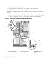
... hard-drive interface and power cables as follows: • For up to two SATA drives, connect the cables to the two SATA connectors on System Board) 6 5 4 1 2 3 1 center fan retention cage 2 power cable connector 4 hard drive interface connector 5 SATA_A connector 62 Installing System Components 3 hard drive interface cable connector 6 SATA_B connector... into the system until the drive bay contacts the system. 3 Install the hard-drive bay. Two-Hard-Drive Configuration (Integrated SATA on the system board. Route the cables through the center fan retention cage. Figure 3-12.
... hard-drive interface and power cables as follows: • For up to two SATA drives, connect the cables to the two SATA connectors on System Board) 6 5 4 1 2 3 1 center fan retention cage 2 power cable connector 4 hard drive interface connector 5 SATA_A connector 62 Installing System Components 3 hard drive interface cable connector 6 SATA_B connector... into the system until the drive bay contacts the system. 3 Install the hard-drive bay. Two-Hard-Drive Configuration (Integrated SATA on the system board. Route the cables through the center fan retention cage. Figure 3-12.
Hardware Owner's Manual (PDF)
Page 63
... an Expansion Card" on page 57) installed into expansion slot 4 (PCIE_X4_4), and connect the hard-drive activity LED cable to the connector on the system board and the connector on the system board. See Figure 6-2 for the locations of these connectors.
... an Expansion Card" on page 57) installed into expansion slot 4 (PCIE_X4_4), and connect the hard-drive activity LED cable to the connector on the system board and the connector on the system board. See Figure 6-2 for the locations of these connectors.
Hardware Owner's Manual (PDF)
Page 64
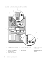
Four-hard-drive Configuration (SAS Controller Card) 3 2 4 5 1 6 7 1 central fan retention bracket 2 expansion-slot 4 (PCIE_X4_4) 3 hard drive activity system board connector 4 hard drive activity system board connector 5 SAS1 connector 6 hard drive interface cable connector 7 power cable connector 64 Installing System Components Figure 3-13.
Four-hard-drive Configuration (SAS Controller Card) 3 2 4 5 1 6 7 1 central fan retention bracket 2 expansion-slot 4 (PCIE_X4_4) 3 hard drive activity system board connector 4 hard drive activity system board connector 5 SAS1 connector 6 hard drive interface cable connector 7 power cable connector 64 Installing System Components Figure 3-13.


