

Getting Started Guide
Page 5
...System Features The major hardware and software features of your system by installing a second processor, you must order the processor upgrade kits from Dell contains the correct version of the processor and heat sink. • A minimum of 512 MB of 533 or 667 MHz (when ... systems management software if the top cover is opened. • An 800-W power supply. • Six system cooling fans. NOTE: DVD devices are 3.3-V, PCIe x4 lanes. Slot 1 accommodates halflength expansion cards. The upgrade kit from Dell. slots 4 through 6 accommodate full-height, full-length expansion cards. NOTE: ...
...System Features The major hardware and software features of your system by installing a second processor, you must order the processor upgrade kits from Dell contains the correct version of the processor and heat sink. • A minimum of 512 MB of 533 or 667 MHz (when ... systems management software if the top cover is opened. • An 800-W power supply. • Six system cooling fans. NOTE: DVD devices are 3.3-V, PCIe x4 lanes. Slot 1 accommodates halflength expansion cards. The upgrade kit from Dell. slots 4 through 6 accommodate full-height, full-length expansion cards. NOTE: ...
Getting Started Guide
Page 9
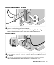
... With Your System 7 Connecting the Power Attach the system's power cable to the cable clasp at the top of your system have icons indicating which cable to the system. Be sure to tighten the screws (if any) on the back of the power supply and connect it to plug into ...a grounded electrical outlet or a separate power source such as an uninterrupted power supply (UPS) or a power distribution unit (PDU). Connecting the Keyboard, Mouse, and Monitor Connect the keyboard, mouse, ...
... With Your System 7 Connecting the Power Attach the system's power cable to the cable clasp at the top of your system have icons indicating which cable to the system. Be sure to tighten the screws (if any) on the back of the power supply and connect it to plug into ...a grounded electrical outlet or a separate power source such as an uninterrupted power supply (UPS) or a power distribution unit (PDU). Connecting the Keyboard, Mouse, and Monitor Connect the keyboard, mouse, ...
Getting Started Guide
Page 12
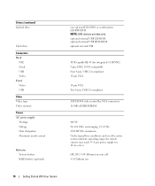
...63 Hz 2320 BTU/hr maximum Under typical line conditions and over the entire system ambient operating range, the inrush current may reach 55 A per power supply for integrated 1-GB NIC) 9-pin, DTE, 16550-compatible Four 4-pin, USB 2.0-compliant 15-pin VGA 15-pin VGA Two 4-pin, USB...With Your System Drives (continued) Optical drive Flash drive Connectors Back NIC Serial USB Video Front Video USB Video Video type Video memory Power AC power supply Wattage Voltage Heat dissipation Maximum inrush current Batteries System battery RAID battery (optional) one optional CD, DVD, or combination CD-RW/DVD ...
...63 Hz 2320 BTU/hr maximum Under typical line conditions and over the entire system ambient operating range, the inrush current may reach 55 A per power supply for integrated 1-GB NIC) 9-pin, DTE, 16550-compatible Four 4-pin, USB 2.0-compliant 15-pin VGA 15-pin VGA Two 4-pin, USB...With Your System Drives (continued) Optical drive Flash drive Connectors Back NIC Serial USB Video Front Video USB Video Video type Video memory Power AC power supply Wattage Voltage Heat dissipation Maximum inrush current Batteries System battery RAID battery (optional) one optional CD, DVD, or combination CD-RW/DVD ...
Hardware Owner's Manual (PDF)
Page 4
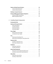
... Opening and Closing the System 46 Removing the Bezel 46 Installing the Bezel 47 Opening the System 48 Closing the System 48 Power Supply 50 Removing the Power Supply 50 Installing the Power Supply 51 Fans 52 Removing and Installing a Fan 53 Removing and Installing the Cooling Shroud Fan 54 Expansion Cards 56 Installing an Expansion...
... Opening and Closing the System 46 Removing the Bezel 46 Installing the Bezel 47 Opening the System 48 Closing the System 48 Power Supply 50 Removing the Power Supply 50 Installing the Power Supply 51 Fans 52 Removing and Installing a Fan 53 Removing and Installing the Cooling Shroud Fan 54 Expansion Cards 56 Installing an Expansion...
Hardware Owner's Manual (PDF)
Page 6
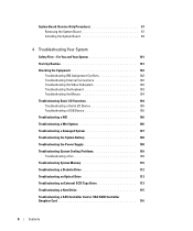
... a Serial I/O Device 105 Troubleshooting a USB Device 105 Troubleshooting a NIC 106 Troubleshooting a Wet System 106 Troubleshooting a Damaged System 107 Troubleshooting the System Battery 108 Troubleshooting the Power Supply 108 Troubleshooting System Cooling Problems 109 Troubleshooting a Fan 109 Troubleshooting System Memory 110 Troubleshooting a Diskette Drive 112 Troubleshooting an Optical Drive 113 Troubleshooting an External...
... a Serial I/O Device 105 Troubleshooting a USB Device 105 Troubleshooting a NIC 106 Troubleshooting a Wet System 106 Troubleshooting a Damaged System 107 Troubleshooting the System Battery 108 Troubleshooting the Power Supply 108 Troubleshooting System Cooling Problems 109 Troubleshooting a Fan 109 Troubleshooting System Memory 110 Troubleshooting a Diskette Drive 112 Troubleshooting an Optical Drive 113 Troubleshooting an External...

Hardware Owner's Manual (PDF)
Page 12
... a rack. Both the system management software and the identification buttons located on the back blink until one of whether the system has been powered on . NOTE: If the system is pushed, the LCD panel on the front and the blue system status indicator on the front and... is not running an ACPI-compliant operating system, the system performs a graceful shutdown before the power is turned off immediately after the power button is turned off . The power button controls the DC power supply output to do so by qualified support personnel or by descriptive text. The LCD lights amber ...
... a rack. Both the system management software and the identification buttons located on the back blink until one of whether the system has been powered on . NOTE: If the system is pushed, the LCD panel on the front and the blue system status indicator on the front and... is not running an ACPI-compliant operating system, the system performs a graceful shutdown before the power is turned off immediately after the power button is turned off . The power button controls the DC power supply output to do so by qualified support personnel or by descriptive text. The LCD lights amber ...
Hardware Owner's Manual (PDF)
Page 14
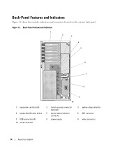
Figure 1-2. Back-Panel Features and Indicators Figure 1-2 shows the controls, indicators, and connectors located on the system's back panel. Back-Panel Features and Indicators 1 2 3 4 5 6 7 8 1 expansion-card slots (6) 4 system identification button 7 USB connectors (4) 10 serial connector 10 2 remote access connector (optional) 5 system status indicator connector 8 power supply 9 3 system status indicator 6 NIC connector 9 video connector 14 About Your System
Figure 1-2. Back-Panel Features and Indicators Figure 1-2 shows the controls, indicators, and connectors located on the system's back panel. Back-Panel Features and Indicators 1 2 3 4 5 6 7 8 1 expansion-card slots (6) 4 system identification button 7 USB connectors (4) 10 serial connector 10 2 remote access connector (optional) 5 system status indicator connector 8 power supply 9 3 system status indicator 6 NIC connector 9 video connector 14 About Your System
Hardware Owner's Manual (PDF)
Page 18
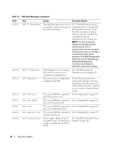
... has reported a See "Getting Help" on page 109. Ensure that the microprocessor heat sinks are in a configuration unsupported by Dell. The system BIOS has reported a See "Getting Help" on page 108. specified power Supply" on page 131. processor initialization error. Table 1-4. If the problem persists, ensure that your system's Getting Started Guide. NOTE...
... has reported a See "Getting Help" on page 109. Ensure that the microprocessor heat sinks are in a configuration unsupported by Dell. The system BIOS has reported a See "Getting Help" on page 108. specified power Supply" on page 131. processor initialization error. Table 1-4. If the problem persists, ensure that your system's Getting Started Guide. NOTE...
Hardware Owner's Manual (PDF)
Page 19
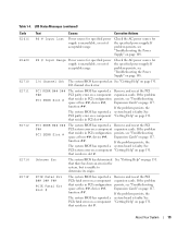
... error in slot #. I /O Channel Chk The system BIOS has reported an See "Getting Help" on page 117. About Your System 19 PS # Input Range Power source for specified power supply is faulty. I /O channel check error. If the problem persists, see "Troubleshooting space at bus ##, device ##, function ##. If the problem that resides in PCI...
... error in slot #. I /O Channel Chk The system BIOS has reported an See "Getting Help" on page 117. About Your System 19 PS # Input Range Power source for specified power supply is faulty. I /O channel check error. If the problem persists, see "Troubleshooting space at bus ##, device ##, function ##. If the problem that resides in PCI...
Hardware Owner's Manual (PDF)
Page 22
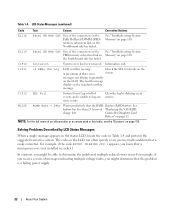
Table 1-4. messages can often specify a very precise fault condition that the problem is a failing power supply. 22 About Your System The code on the LCD can display sequentially on the LCD. Check the SEL for details on the A maximum of an ...
Table 1-4. messages can often specify a very precise fault condition that the problem is a failing power supply. 22 About Your System The code on the LCD can display sequentially on the LCD. Check the SEL for details on the A maximum of an ...
Hardware Owner's Manual (PDF)
Page 45
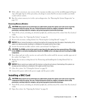
Installing System Components This section describes how to install the following system components: • Power supply • Cooling fans • Expansion cards • Hard drives • Tape, optical, and diskette drives • System battery • System memory • RAC card • ...
Installing System Components This section describes how to install the following system components: • Power supply • Cooling fans • Expansion cards • Hard drives • Tape, optical, and diskette drives • System battery • System memory • RAC card • ...
Hardware Owner's Manual (PDF)
Page 50
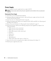
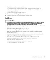
...Center Fan Bracket" on page 79. 6 Disconnect the power cables from the following components where applicable (see Figure 3-4) 7 Remove the four screws securing the power supply to the back panel. Power Supply Your system supports one power supply rated at an output of 800 W. See "Opening the...and FAN3). See "Removing and Installing a Fan" on the unoccupied power supply bay. See Figure 3-4. 8 Slide the power supply from the cable retention bracket. 3 Open the system. NOTICE: To ensure proper system cooling, the power supply blank must be installed on page 53. 5 Remove the center fan...
...Center Fan Bracket" on page 79. 6 Disconnect the power cables from the following components where applicable (see Figure 3-4) 7 Remove the four screws securing the power supply to the back panel. Power Supply Your system supports one power supply rated at an output of 800 W. See "Opening the...and FAN3). See "Removing and Installing a Fan" on the unoccupied power supply bay. See Figure 3-4. 8 Slide the power supply from the cable retention bracket. 3 Open the system. NOTICE: To ensure proper system cooling, the power supply blank must be installed on page 53. 5 Remove the center fan...
Hardware Owner's Manual (PDF)
Page 51
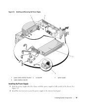
Figure 3-4. Installing and Removing the Power Supply 1 2 3 4 1 power cable retention bracket 2 4 cable retention clips (3) screws (4) 3 power supply Installing the Power Supply 1 Slide the power supply into the chassis until the power supply is fully seated in the chassis. See Figure 3-4. 2 Install the four screws to secure the power supply to the system's back panel. Installing System Components 51
Figure 3-4. Installing and Removing the Power Supply 1 2 3 4 1 power cable retention bracket 2 4 cable retention clips (3) screws (4) 3 power supply Installing the Power Supply 1 Slide the power supply into the chassis until the power supply is fully seated in the chassis. See Figure 3-4. 2 Install the four screws to secure the power supply to the system's back panel. Installing System Components 51
Hardware Owner's Manual (PDF)
Page 52
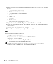
... on top of a problem with a particular fan, the fan's number is referenced by the systems management software, allowing you to the power supply and the power outlet. See "Removing and Installing a Fan" on page 79. 5 Replace the expansion-bay and processor fans (FAN1, FAN2, and FAN3...the memory cooling shroud (FAN4) - See "Closing the System" on page 48. 7 Connect the power cable to easily identify and replace the proper fan. 52 Installing System Components 3 Connect the power cables to the following components where applicable (see Figure 3-4) 4 Replace the center fan bracket.
... on top of a problem with a particular fan, the fan's number is referenced by the systems management software, allowing you to the power supply and the power outlet. See "Removing and Installing a Fan" on page 79. 5 Replace the expansion-bay and processor fans (FAN1, FAN2, and FAN3...the memory cooling shroud (FAN4) - See "Closing the System" on page 48. 7 Connect the power cable to easily identify and replace the proper fan. 52 Installing System Components 3 Connect the power cables to the following components where applicable (see Figure 3-4) 4 Replace the center fan bracket.
Hardware Owner's Manual (PDF)
Page 58
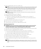
... the stabilizer pivot slots. NOTE: Ensure that are connected to the expansion card. 5 Open the expansion-card retainer adjacent to the power supply and the power outlet. Removing an Expansion Card CAUTION: Only trained service technicians are authorized to maintain Federal Communications Commission (FCC) certification of the system... Rotate the end of the stabilizer down toward the front of the system. See "Closing the System" on page 48. 11 Connect the power cable to the slot. b Draw the stabilizer straight up from the tab slots and out of the system. 4 Disconnect any internal or ...
... the stabilizer pivot slots. NOTE: Ensure that are connected to the expansion card. 5 Open the expansion-card retainer adjacent to the power supply and the power outlet. Removing an Expansion Card CAUTION: Only trained service technicians are authorized to maintain Federal Communications Commission (FCC) certification of the system... Rotate the end of the stabilizer down toward the front of the system. See "Closing the System" on page 48. 11 Connect the power cable to the slot. b Draw the stabilizer straight up from the tab slots and out of the system. 4 Disconnect any internal or ...
Hardware Owner's Manual (PDF)
Page 59
8 If applicable, reinstall the expansion-card stabilizer: a Insert the two round tabs on page 48. 11 Connect the power cable to the power supply and the power outlet. b Rotate the end of the stabilizer down toward the front of the components inside the computer, and protecting against the chassis. 9 Close ... card, and pull the cable out of the way of the system. See "Removing and Installing a Fan" on page 79. 7 Disconnect the interface and power cables from the electrical outlet. 2 Remove the bezel. See Figure 3-10. b Slide the hard-drive bay out of the center fans. 6 Remove the ...
8 If applicable, reinstall the expansion-card stabilizer: a Insert the two round tabs on page 48. 11 Connect the power cable to the power supply and the power outlet. b Rotate the end of the stabilizer down toward the front of the components inside the computer, and protecting against the chassis. 9 Close ... card, and pull the cable out of the way of the system. See "Removing and Installing a Fan" on page 79. 7 Disconnect the interface and power cables from the electrical outlet. 2 Remove the bezel. See Figure 3-10. b Slide the hard-drive bay out of the center fans. 6 Remove the ...
Hardware Owner's Manual (PDF)
Page 67
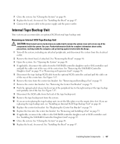
.... 2 Remove the front bezel, if attached. See "Removing the Bezel" on page 47. 9 Connect the power cable to the right and eject the tape backup unit partially out of the peripheral bay to the power supply and the power outlet. See "Installing the Bezel" on page 46. 3 Open the system. See "Closing the System...
.... 2 Remove the front bezel, if attached. See "Removing the Bezel" on page 47. 9 Connect the power cable to the right and eject the tape backup unit partially out of the peripheral bay to the power supply and the power outlet. See "Installing the Bezel" on page 46. 3 Open the system. See "Closing the System...
Hardware Owner's Manual (PDF)
Page 71
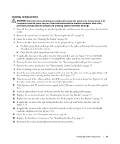
... Fan Bracket" on the rear of the optical drive. 12 Push the optical drive the rest of the center fans. 6 Remove the fans from the power supply to the SAS controller card (see Figure 3-13) or the SAS RAID controller daughter card (see Figure 3-14) and pull the cables out of the... way of the way into the center fan bracket. See Figure 3-15. 16 If applicable, reconnect the cables to the CD power connect or on page 79. 14 Replace the fans into the bay until the spring latch engages. 13 Replace the center fan bracket. See "Installing...
... Fan Bracket" on the rear of the optical drive. 12 Push the optical drive the rest of the center fans. 6 Remove the fans from the power supply to the SAS controller card (see Figure 3-13) or the SAS RAID controller daughter card (see Figure 3-14) and pull the cables out of the... way of the way into the center fan bracket. See Figure 3-15. 16 If applicable, reconnect the cables to the CD power connect or on page 79. 14 Replace the fans into the bay until the spring latch engages. 13 Replace the center fan bracket. See "Installing...
Hardware Owner's Manual (PDF)
Page 75
...connector (FLOPPY) on the system board (Figure 6-2) and the other end to the connector on the rear of the diskette drive. 8 Attach power cable P4 from the electrical outlet. 3 Open the system. System Battery Replacing the System Battery CAUTION: Only trained service technicians are authorized to ...Removing an Expansion Card" on page 33. 2 Turn off the system, including any attached peripherals, and disconnect the system from the power supply to the power connector on page 47. 12 Reconnect the system and peripherals to remove the system cover and access any of the system battery and then...
...connector (FLOPPY) on the system board (Figure 6-2) and the other end to the connector on the rear of the diskette drive. 8 Attach power cable P4 from the electrical outlet. 3 Open the system. System Battery Replacing the System Battery CAUTION: Only trained service technicians are authorized to ...Removing an Expansion Card" on page 33. 2 Turn off the system, including any attached peripherals, and disconnect the system from the power supply to the power connector on page 47. 12 Reconnect the system and peripherals to remove the system cover and access any of the system battery and then...
Hardware Owner's Manual (PDF)
Page 85
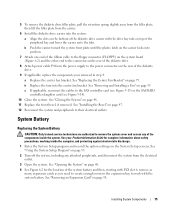
...See Figure 6-2. CAUTION: The DIMMs are authorized to cool before handling them. Allow time for some time after the system has been powered down. See your system with the memory cooling shroud removed. NOTICE: Never operate your Product Information Guide for complete information about safety...Open the system. Repeat step 2 through step 12 of this procedure, checking to ensure that the memory modules are authorized to the power supply and the power outlet. See "Running the System Diagnostics" on the system board. Handle the DIMMs by the card edges and avoid touching the ...
...See Figure 6-2. CAUTION: The DIMMs are authorized to cool before handling them. Allow time for some time after the system has been powered down. See your system with the memory cooling shroud removed. NOTICE: Never operate your Product Information Guide for complete information about safety...Open the system. Repeat step 2 through step 12 of this procedure, checking to ensure that the memory modules are authorized to the power supply and the power outlet. See "Running the System Diagnostics" on the system board. Handle the DIMMs by the card edges and avoid touching the ...


