
User Manual
Page 86
... with the most recently saved configuration. Additionally, the PowerConnect 7024P and PowerConnect 7048P switches contain LEDs that the LEDs indicate, see "LED Definitions" on the ports. Port and System LEDs The front panel contains light emitting diodes (LEDs) that were not saved to the startup configuration prior...stack member. For information about the status that provide information about Power over Ethernet Plus (PoE+) status and activity on page 91. Any changes made to the running configuration that indicate the status of a stack, the M LED is illuminated and the stack unit...
... with the most recently saved configuration. Additionally, the PowerConnect 7024P and PowerConnect 7048P switches contain LEDs that the LEDs indicate, see "LED Definitions" on the ports. Port and System LEDs The front panel contains light emitting diodes (LEDs) that were not saved to the startup configuration prior...stack member. For information about the status that provide information about Power over Ethernet Plus (PoE+) status and activity on page 91. Any changes made to the running configuration that indicate the status of a stack, the M LED is illuminated and the stack unit...
User Manual
Page 95
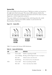
... the right side of the front panel. Figure 3-14. System LED Definitions LED Status FAN Color Definition Green solid Switch is in the PowerConnect 7000 Series. Red blinking Non-critical system error detected. Green solid Fans are located on the front panel ... and provide information about the status of the switch depend on each model in progress. Figure 3-14 shows the LEDs available on the switch model. System LEDs The system LEDs for the PowerConnect 7000 Series switches are operating normally. System LEDs PWR Status PWR Status PWR1 Status M MPS Fan PC7024 PC7024F ...
... the right side of the front panel. Figure 3-14. System LED Definitions LED Status FAN Color Definition Green solid Switch is in the PowerConnect 7000 Series. Red blinking Non-critical system error detected. Green solid Fans are located on the front panel ... and provide information about the status of the switch depend on each model in progress. Figure 3-14 shows the LEDs available on the switch model. System LEDs The system LEDs for the PowerConnect 7000 Series switches are operating normally. System LEDs PWR Status PWR Status PWR1 Status M MPS Fan PC7024 PC7024F ...

User Manual
Page 96
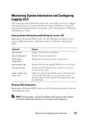
.... Off Non-master stack unit. The PWR1 LED indicates the status of the first power supply, and the PWR2 LEDs indicates the status of the second power supply. 96 Hardware Overview Table 3-8. System LED Definitions (Continued) LED PWRa Color Green solid Definition Power Supply is always the master. The PowerConnect 7048R has two power supplies. Red solid...
.... Off Non-master stack unit. The PWR1 LED indicates the status of the first power supply, and the PWR2 LEDs indicates the status of the second power supply. 96 Hardware Overview Table 3-8. System LED Definitions (Continued) LED PWRa Color Green solid Definition Power Supply is always the master. The PowerConnect 7048R has two power supplies. Red solid...
User Manual
Page 259
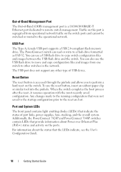
... the CPU utilization for each process currently running any cable diagnostics. Enable the switch locator LED located on the switch. Monitoring and Logging System Information 259 Displays the power supply status. Disable green mode prior to monitor the PowerConnect 7000 Series switch. Running Cable Diagnostics Beginning in Privileged EXEC mode, use the following...
... the CPU utilization for each process currently running any cable diagnostics. Enable the switch locator LED located on the switch. Monitoring and Logging System Information 259 Displays the power supply status. Disable green mode prior to monitor the PowerConnect 7000 Series switch. Running Cable Diagnostics Beginning in Privileged EXEC mode, use the following...

Getting Started Guide
Page 11
...difference between crossed and straight-through cables on the PowerConnect 7024, PowerConnect 7024F, and PowerConnect 7048 switches. The default baud rate is for all models. The front panel also contains a reset button (pinhole) and several status LEDs. The console port supports asynchronous data of power per... port. and full-duplex mode 10/100/1000 Mbps. The PowerConnect 7024F front panel provides 20 Gigabit Ethernet (10/100/1000BASE-FX)...
...difference between crossed and straight-through cables on the PowerConnect 7024, PowerConnect 7024F, and PowerConnect 7048 switches. The default baud rate is for all models. The front panel also contains a reset button (pinhole) and several status LEDs. The console port supports asynchronous data of power per... port. and full-duplex mode 10/100/1000 Mbps. The PowerConnect 7024F front panel provides 20 Gigabit Ethernet (10/100/1000BASE-FX)...
Getting Started Guide
Page 12
... were not saved to the startup configuration prior to the operational network. Additionally, the PowerConnect 7024P and PowerConnect 7048P switches contain LEDs that indicate the status of port links, power supplies, fans, stacking, and the overall system. USB Port The Type-A, female USB port supports a USB 2.0-... a 10/100/1000BASE-T Ethernet port dedicated to copy switch configuration files and images between the USB flash drive and the switch. The PowerConnect switch can use the reset button, insert an unbent paper clip or similar tool into the pinhole. To use a USB flash drive to...
... were not saved to the startup configuration prior to the operational network. Additionally, the PowerConnect 7024P and PowerConnect 7048P switches contain LEDs that indicate the status of port links, power supplies, fans, stacking, and the overall system. USB Port The Type-A, female USB port supports a USB 2.0-... a 10/100/1000BASE-T Ethernet port dedicated to copy switch configuration files and images between the USB flash drive and the switch. The PowerConnect switch can use the reset button, insert an unbent paper clip or similar tool into the pinhole. To use a USB flash drive to...

