User's Guide (.htm)
Page 4
3 Cable, Port, and Pinout Information Pin Connections for the 10/100/1000 Ethernet Interface 45 Pin Connections for SFP Interfaces 46 Serial Cable Connection 47 Connecting the Switch to a Terminal 48 AC Power Connection 49 4 Using Dell OpenManage Switch Administrator Starting the Application 51 Understanding the Interface 51 Using the Switch Administrator Buttons 53 Information Buttons 53 Device...
3 Cable, Port, and Pinout Information Pin Connections for the 10/100/1000 Ethernet Interface 45 Pin Connections for SFP Interfaces 46 Serial Cable Connection 47 Connecting the Switch to a Terminal 48 AC Power Connection 49 4 Using Dell OpenManage Switch Administrator Starting the Application 51 Understanding the Interface 51 Using the Switch Administrator Buttons 53 Information Buttons 53 Device...
User's Guide (.htm)
Page 13
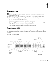
...and management features. • High availability with hot swappable power supplies and cooling fans PowerConnect 6024 The PowerConnect 6024 provides 24 10/100/1000 Base-T RJ-45 ports with eight SFP combo ports that extends the Dell PowerConnect LAN switching product range. SFP transceivers are sold separately.... The switch includes the following features: • 1U form factor, rack-mountable chassis design • Out-of-band management port for RJ-45 and RS-232 connections. •...
...and management features. • High availability with hot swappable power supplies and cooling fans PowerConnect 6024 The PowerConnect 6024 provides 24 10/100/1000 Base-T RJ-45 ports with eight SFP combo ports that extends the Dell PowerConnect LAN switching product range. SFP transceivers are sold separately.... The switch includes the following features: • 1U form factor, rack-mountable chassis design • Out-of-band management port for RJ-45 and RS-232 connections. •...
User's Guide (.htm)
Page 29
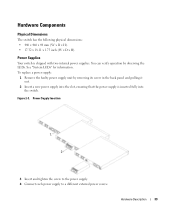
.... You can verify operation by removing its screw in the back panel and pulling it out. 2 Insert a new power supply into the switch. Power Supply Insertion 1 2 3 Insert and tighten the screw to the power supply. 4 Connect each power supply to a different external power source. To replace a power supply: 1 Remove the faulty power supply unit by observing the LEDs.
.... You can verify operation by removing its screw in the back panel and pulling it out. 2 Insert a new power supply into the switch. Power Supply Insertion 1 2 3 Insert and tighten the screw to the power supply. 4 Connect each power supply to a different external power source. To replace a power supply: 1 Remove the faulty power supply unit by observing the LEDs.
User's Guide (.htm)
Page 30
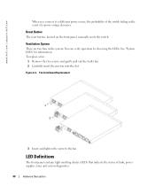
..."System LEDs" for information. LED Definitions The front panel contains light emitting diodes (LED) that indicate the status of a power outage decreases. www.dell.com | support.dell.com When you connect to the fan. Reset Button The reset button, located on the front panel, manually resets the switch. You can verify... the faulty fan. 2 Carefully insert the new fan into the slot. Fan Installment/Replacement 1 2 3 Insert and tighten the screw to a different power source, the probability of the switch failing in the system. Ventilation System There are two fans in the event of links...
..."System LEDs" for information. LED Definitions The front panel contains light emitting diodes (LED) that indicate the status of a power outage decreases. www.dell.com | support.dell.com When you connect to the fan. Reset Button The reset button, located on the front panel, manually resets the switch. You can verify... the faulty fan. 2 Carefully insert the new fan into the slot. Fan Installment/Replacement 1 2 3 Insert and tighten the screw to a different power source, the probability of the switch failing in the system. Ventilation System There are two fans in the event of links...
User's Guide (.htm)
Page 37
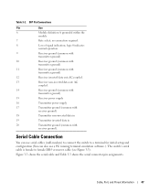
... assignments. Table 3-2. AC coupled. 14 Receiver ground (common with transmitter ground) 15 Receiver power supply 16 Transmitter power supply 17 Transmitter ground (common with receiver ground) 18 Transmitter non-inverted data in 19 ...Transmitter inverted data in 20 Transmitter ground (common with transmitter ground) 12 Receiver inverted data out; Cable, Port, and Pinout Information 47 grounded within the module 7 Rate select; Serial Cable Connection...
... assignments. Table 3-2. AC coupled. 14 Receiver ground (common with transmitter ground) 15 Receiver power supply 16 Transmitter power supply 17 Transmitter ground (common with receiver ground) 18 Transmitter non-inverted data in 19 ...Transmitter inverted data in 20 Transmitter ground (common with transmitter ground) 12 Receiver inverted data out; Cable, Port, and Pinout Information 47 grounded within the module 7 Rate select; Serial Cable Connection...
User's Guide (.htm)
Page 39
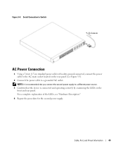
... Information 49 For a complete explanation of the LEDs, see Figure 3-5). 2 Connect the power cable to a grounded AC outlet. Figure 3-4. Serial Connection to Switch To Console AC Power Connection 1 Using a 5-foot (1.5 m) standard power cable with safety ground connected, connect the power cable to a different power source. 3 Confirm that the device is connected and operating correctly by examining the LEDs on the rear...
... Information 49 For a complete explanation of the LEDs, see Figure 3-5). 2 Connect the power cable to a grounded AC outlet. Figure 3-4. Serial Connection to Switch To Console AC Power Connection 1 Using a 5-foot (1.5 m) standard power cable with safety ground connected, connect the power cable to a different power source. 3 Confirm that the device is connected and operating correctly by examining the LEDs on the rear...

User's Guide (.htm)
Page 40
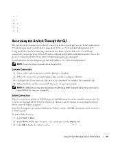
www.dell.com | support.dell.com Figure 3-5. AC Power Connection to Switch 50 Cable, Port, and Pinout Information
www.dell.com | support.dell.com Figure 3-5. AC Power Connection to Switch 50 Cable, Port, and Pinout Information
User's Guide (.htm)
Page 45
..."Initial Configuration." Console Connection 1 Power on a Linux system. ASCII terminals can be managed over a telnet session. If access is via a Telnet connection, ensure the device has an IP address defined and that the workstation used over a direct connection to the console port or via a Telnet connection. NOTE: If a...the CLI. Your switch supports up to a local login terminal where a remote login is a terminal emulation TCP/IP protocol. Using Dell OpenManage Switch Administrator 55 Using the CLI is logged in the Open field. 3 Click OK to begin the Telnet session. All CLI...
..."Initial Configuration." Console Connection 1 Power on a Linux system. ASCII terminals can be managed over a telnet session. If access is via a Telnet connection, ensure the device has an IP address defined and that the workstation used over a direct connection to the console port or via a Telnet connection. NOTE: If a...the CLI. Your switch supports up to a local login terminal where a remote login is a terminal emulation TCP/IP protocol. Using Dell OpenManage Switch Administrator 55 Using the CLI is logged in the Open field. 3 Click OK to begin the Telnet session. All CLI...

User's Guide (.htm)
Page 50
www.dell.com | support.dell.com Figure 5-1. Installation and Configuration Jobflow Connect Device and Console Power on Hardware Setup Yes Suspend Bootup Press Esc Startup Menu (Special functions) Reboot No Loading program from flash to RAM Yes Enter Wizard No Initial Configuration: IP Address, Subnetmask, Users Basic Security configuration Wizard Configuration Process Standard Device Installation Advanced Configuration: IP Address from DHCP, IP Address from bootp, Security management Advanced Device Installation 60 Configuring the Switch
www.dell.com | support.dell.com Figure 5-1. Installation and Configuration Jobflow Connect Device and Console Power on Hardware Setup Yes Suspend Bootup Press Esc Startup Menu (Special functions) Reboot No Loading program from flash to RAM Yes Enter Wizard No Initial Configuration: IP Address, Subnetmask, Users Basic Security configuration Wizard Configuration Process Standard Device Installation Advanced Configuration: IP Address from DHCP, IP Address from bootp, Security management Advanced Device Installation 60 Configuring the Switch
User's Guide (.htm)
Page 53
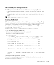
... or Esc. Other Configuration Requirements The following is required for device remote control use with the local terminal already connected, the switch goes through Power On Self Test (POST). POST runs every time the device is fully operational before completely booting. The auto-...boot message that the ASCII cable is connected to the terminal. 2 Connect the power supply to determine if the device is initialized and checks hardware components to the switch. 3 Power on the terminal and indicate test success or failure.
... or Esc. Other Configuration Requirements The following is required for device remote control use with the local terminal already connected, the switch goes through Power On Self Test (POST). POST runs every time the device is fully operational before completely booting. The auto-...boot message that the ASCII cable is connected to the terminal. 2 Connect the power supply to determine if the device is initialized and checks hardware components to the switch. 3 Power on the terminal and indicate test success or failure.

User's Guide (.htm)
Page 67
... server and programming it into the flash updates the boot image. Do you want to continue (y/n) [n] ? 6 Enter Y to establish a remote network management connection with the switch. Configuring the Switch 77 The following message is displayed: console# reload This command will reset the whole system and disconnect your current...image is loaded when the switch is an example of the information that appears: console# show version to the switch. The following is powered on the switch or the relevant commands. This section does not explain the various configurations available on .
... server and programming it into the flash updates the boot image. Do you want to continue (y/n) [n] ? 6 Enter Y to establish a remote network management connection with the switch. Configuring the Switch 77 The following message is displayed: console# reload This command will reset the whole system and disconnect your current...image is loaded when the switch is an example of the information that appears: console# show version to the switch. The following is powered on the switch or the relevant commands. This section does not explain the various configurations available on .

User's Guide (.htm)
Page 68
...browser application • One Null Modem F2F cable. • Straight or cross UTP (category 5) cable(s) Initial Connection 1 Using the RS-232 port, connect the switch to the workstation. 2 Set the ASCII terminal with the following components installed: - Device Setup Requirements ... purpose of device when powered up-should be erased and device rebooted, see "Device Default Settings." which is the configuration of this example: • PowerConnect 6024/6024F switch • A workstation with the default configuration and definitions. www.dell.com | support.dell.com This section also...
...browser application • One Null Modem F2F cable. • Straight or cross UTP (category 5) cable(s) Initial Connection 1 Using the RS-232 port, connect the switch to the workstation. 2 Set the ASCII terminal with the following components installed: - Device Setup Requirements ... purpose of device when powered up-should be erased and device rebooted, see "Device Default Settings." which is the configuration of this example: • PowerConnect 6024/6024F switch • A workstation with the default configuration and definitions. www.dell.com | support.dell.com This section also...

User's Guide (.htm)
Page 69
The following screen is the default baud rate for new device. If using the 115,200 baud rate does not result in viewing the device terminal, try other baud rate. 3 Use an F2F null modem cable to connect the workstation to the switch. 4 Connect the device power cord and power up the device. HyperTerminal Properties Window NOTE: 115,200 is displayed: SYSTEM RESET Booting... The device may have another baud rate. Boot1 Checksum Test PASS Boot2 Checksum Test PASS Flash Image Validation Test PASS Configuring the Switch 79 Figure 5-2.
The following screen is the default baud rate for new device. If using the 115,200 baud rate does not result in viewing the device terminal, try other baud rate. 3 Use an F2F null modem cable to connect the workstation to the switch. 4 Connect the device power cord and power up the device. HyperTerminal Properties Window NOTE: 115,200 is displayed: SYSTEM RESET Booting... The device may have another baud rate. Boot1 Checksum Test PASS Boot2 Checksum Test PASS Flash Image Validation Test PASS Configuring the Switch 79 Figure 5-2.


