Command Line Interface Guide
Page 197
... 197 The test is up. Command Mode Privileged EXEC mode User Guidelines • To test optical transceivers, ensure a fiber link is only supported on Dell supported SFP modules. Example The following example displays the estimated copper cable length attached to all ports. Syntax show fiber-ports optical-transceiver Privileged EXEC mode command...
... 197 The test is up. Command Mode Privileged EXEC mode User Guidelines • To test optical transceivers, ensure a fiber link is only supported on Dell supported SFP modules. Example The following example displays the estimated copper cable length attached to all ports. Syntax show fiber-ports optical-transceiver Privileged EXEC mode command...
User's Guide
Page 10
... 6-20. Figure 4-12. Figure 6-22. Figure 6-26. PowerConnect 5324 Front Panel 19 PowerConnect 5324 Back Panel 19 PowerConnect 5324 Front Panel 29 Device Back Panel 30 Console Port 30 RJ-45 Copper based 10/100/1000 BaseT LEDs . . . . 31 SFP Port LED 32 System LEDs 33 Connection Rack Mounting Brackets 37 ...Connecting to PowerConnect 5324 Console Port . . 39 Connecting to Device Power Connector 40 Installation and Configuration Flow 43 Switch ...
... 6-20. Figure 4-12. Figure 6-22. Figure 6-26. PowerConnect 5324 Front Panel 19 PowerConnect 5324 Back Panel 19 PowerConnect 5324 Front Panel 29 Device Back Panel 30 Console Port 30 RJ-45 Copper based 10/100/1000 BaseT LEDs . . . . 31 SFP Port LED 32 System LEDs 33 Connection Rack Mounting Brackets 37 ...Connecting to PowerConnect 5324 Console Port . . 39 Connecting to Device Power Connector 40 Installation and Configuration Flow 43 Switch ...

User's Guide
Page 15
Table 5-7. Table 6-20. Table 6-27. Table 3-6. Table 5-8. Table 5-10. Table 6-11. Table 6-25. Table 6-26. Table 3-4. Table 6-19. Table 6-23. Table 5-9. Table 6-15. Table 6-18. SFP Port LED Indications 32 System LED Indications 33 Ports, Connectors and Cables 41 RJ-45 Pin Number Allocation for 10/100/1000BaseT Ethernet Port 41 ...
Table 5-7. Table 6-20. Table 6-27. Table 3-6. Table 5-8. Table 5-10. Table 6-11. Table 6-25. Table 6-26. Table 3-4. Table 6-19. Table 6-23. Table 5-9. Table 6-15. Table 6-18. SFP Port LED Indications 32 System LED Indications 33 Ports, Connectors and Cables 41 RJ-45 Pin Number Allocation for 10/100/1000BaseT Ethernet Port 41 ...
User's Guide
Page 19
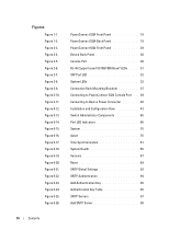
...proceeding, read the release notes for installing, configuring and maintaining the PowerConnect device. This User Guide contains the information needed for this product. Figure 1-1. PowerConnect 5324 Back Panel Features This section describes the device user-configured features. ...the PowerConnect 5324 front and back panels. There are also four SFP fiber ports that are single ports with two physical connections. PowerConnect 5324 Front Panel Figure 1-2. Introduction 19 The release notes can be downloaded from support.dell.com. PowerConnect 5324 The PowerConnect 5324 has ...
...proceeding, read the release notes for installing, configuring and maintaining the PowerConnect device. This User Guide contains the information needed for this product. Figure 1-1. PowerConnect 5324 Back Panel Features This section describes the device user-configured features. ...the PowerConnect 5324 front and back panels. There are also four SFP fiber ports that are single ports with two physical connections. PowerConnect 5324 Front Panel Figure 1-2. Introduction 19 The release notes can be downloaded from support.dell.com. PowerConnect 5324 The PowerConnect 5324 has ...

User's Guide
Page 29
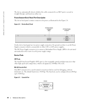
...1000 BaseT Gigabit Ethernet ports • 4 Fiber ports - RJ-45 ports designated as Gigabit ports • Terminal port - PowerConnect 5324 Front Panel The front panel contains ports1-24, which are marked with two physical connections. There are designated as 10/100/1000 ... Button which are four SFP fiber ports which is used to manually reset the device. RS-232 console based port The following ports: • 24 Copper ports - Hardware Description Device Port Configurations PowerConnect 5324 Front Panel Port Description The PowerConnect 5324 device is configured with ...
...1000 BaseT Gigabit Ethernet ports • 4 Fiber ports - RJ-45 ports designated as Gigabit ports • Terminal port - PowerConnect 5324 Front Panel The front panel contains ports1-24, which are marked with two physical connections. There are designated as 10/100/1000 ... Button which are four SFP fiber ports which is used to manually reset the device. RS-232 console based port The following ports: • 24 Copper ports - Hardware Description Device Port Configurations PowerConnect 5324 Front Panel Port Description The PowerConnect 5324 device is configured with ...
User's Guide
Page 30
... The Small Form Factor Plugable (SFP) port is a hot swappable optical modular transceiver that offers high speed and compactness, which is to connect a Redundant Power Supply (RPS) to be configured from 2400 bps up to 38400 bps. PowerConnect Back Panel Port Description The device back panel contains ... The default baud rate is connectable to either way. The baud rate can be activated automatically in the Figure 2-4. Figure 2-4. www.dell.com | support.dell.com The device automatically detects whether the cable connected to an RJ-45 port is used for power, as 1000Base-SX or LX...
... The Small Form Factor Plugable (SFP) port is a hot swappable optical modular transceiver that offers high speed and compactness, which is to connect a Redundant Power Supply (RPS) to be configured from 2400 bps up to 38400 bps. PowerConnect Back Panel Port Description The device back panel contains ... The default baud rate is connectable to either way. The baud rate can be activated automatically in the Figure 2-4. Figure 2-4. www.dell.com | support.dell.com The device automatically detects whether the cable connected to an RJ-45 port is used for power, as 1000Base-SX or LX...
User's Guide
Page 31
...link/activity is indicated on the left LED and the duplex mode is indicated on a combo port, and utilizes this information in the SFP port, the SFP port is active, unless the copper connector of the Base-T port of links, power supplies, fans, and system diagnostics. RJ-45 Copper... Ports A combo port is a single logical port with two physical connections: • A RJ-45 connection for Twisted Pair copper cabling • A SFP connection for various fiber-based modules Only one time. Port features and available port controls are present, and a connector is inserted in all operations and...
...link/activity is indicated on the left LED and the duplex mode is indicated on a combo port, and utilizes this information in the SFP port, the SFP port is active, unless the copper connector of the Base-T port of links, power supplies, fans, and system diagnostics. RJ-45 Copper... Ports A combo port is a single logical port with two physical connections: • A RJ-45 connection for Twisted Pair copper cabling • A SFP connection for various fiber-based modules Only one time. Port features and available port controls are present, and a connector is inserted in all operations and...

User's Guide
Page 32
... The port is linked at 1000 Mbps. Figure 2-7. The port is transmitting or receiving data at either 10 or 100 Mbps. SFP Port LED The SFP port LED indications are described in the following table: Table 2-2. The port is transmitting or receiving data at 1000 Mbps. Green Flashing... Hardware Description The port is currently transmitting in Half Duplex mode. The port is linked at either 10 or 100 Mbps. www.dell.com | support.dell.com The RJ-45 LED indications are described in the following table: Table 2-1. System LEDs The system LEDs, located on the corresponding...
... The port is linked at 1000 Mbps. Figure 2-7. The port is transmitting or receiving data at either 10 or 100 Mbps. SFP Port LED The SFP port LED indications are described in the following table: Table 2-2. The port is transmitting or receiving data at 1000 Mbps. Green Flashing... Hardware Description The port is currently transmitting in Half Duplex mode. The port is linked at either 10 or 100 Mbps. www.dell.com | support.dell.com The RJ-45 LED indications are described in the following table: Table 2-1. System LEDs The system LEDs, located on the corresponding...

User's Guide
Page 144
Not Supported, W - Error. Loss of signal. • Data Ready - NOTE: Fiber Optic analysis feature works only on SFPs that support the digital diagnostic standard SFF4872. 144 Configuring System Information www.dell.com | support.dell.com • LOS - Not Available, N/S - The transceiver has archived power up and data is ready. • N/A - Warning, E -
Not Supported, W - Error. Loss of signal. • Data Ready - NOTE: Fiber Optic analysis feature works only on SFPs that support the digital diagnostic standard SFF4872. 144 Configuring System Information www.dell.com | support.dell.com • LOS - Not Available, N/S - The transceiver has archived power up and data is ready. • N/A - Warning, E -

User's Guide
Page 351
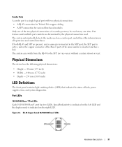
...• Broadcast Storm Control Device Specifications 351 Port and Cable Specifications This section describes the port specifications. Port Specifications Device Specification PowerConnect 5324 • 24 GE ports • 4 SFP ports • RS-232 Console port Port Types RJ-45 • 10 Base-T • 100 Base-T • 1000 ...Base-T SFP Supports Standard Small Form-Factor Gigabit Plug Transceivers Port Settings • Auto-negotiation for running the device. Table 10-99. ...
...• Broadcast Storm Control Device Specifications 351 Port and Cable Specifications This section describes the port specifications. Port Specifications Device Specification PowerConnect 5324 • 24 GE ports • 4 SFP ports • RS-232 Console port Port Types RJ-45 • 10 Base-T • 100 Base-T • 1000 ...Base-T SFP Supports Standard Small Form-Factor Gigabit Plug Transceivers Port Settings • Auto-negotiation for running the device. Table 10-99. ...

User's Guide
Page 357
... data transmitted cannot be used to the Layer II header of tagging IP packets with two physical connections, including an RJ-45 connection and an SFP connection. DSCP DiffServe Code Point (DSCP). Forwarded message responses are grouped with priority information. CPUs are two different types of a control unit and an ALU...
... data transmitted cannot be used to the Layer II header of tagging IP packets with two physical connections, including an RJ-45 connection and an SFP connection. DSCP DiffServe Code Point (DSCP). Forwarded message responses are grouped with priority information. CPUs are two different types of a control unit and an ALU...

User's Guide
Page 369
... Control Page, 316 RPS, 33 RSTP, 23, 363 Rule, 149 Rules, 145-146 Running Configuration file, 186 RVSP, 363 S Secure Shell, 155 Security, 145, 197 SFP, 32 Simple Network Management Protocol, 25, 177, 363 Simple Network Time Protocol, 26, 90 SNMP, 25, 145, 177-178, 182, 363 Index 3
... Control Page, 316 RPS, 33 RSTP, 23, 363 Rule, 149 Rules, 145-146 Running Configuration file, 186 RVSP, 363 S Secure Shell, 155 Security, 145, 197 SFP, 32 Simple Network Management Protocol, 25, 177, 363 Simple Network Time Protocol, 26, 90 SNMP, 25, 145, 177-178, 182, 363 Index 3

