
Command Line Interface Guide
Page 198
www.dell.com | support.dell.com Examples The following example displays the optical transceiver diagnostics. Output Power ------ Input Power - console# show fiber-ports optical-transceiver Port Temp Voltage ---g3 g21 g22 ----Copper W OK ------- Measured TX output power. Measured RX received power. LOS - Loss of signal 198 PHY Diagnostics Commands Voltage - Internally measured supply voltage. Measured TX bias...
www.dell.com | support.dell.com Examples The following example displays the optical transceiver diagnostics. Output Power ------ Input Power - console# show fiber-ports optical-transceiver Port Temp Voltage ---g3 g21 g22 ----Copper W OK ------- Measured TX output power. Measured RX received power. LOS - Loss of signal 198 PHY Diagnostics Commands Voltage - Internally measured supply voltage. Measured TX bias...
Command Line Interface Guide
Page 199
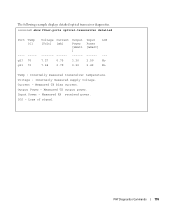
... voltage. Current - Internally measured transceiver temperature. Measured RX received power. Voltage - LOS - Measured TX output power. console# show fiber-ports optical-transceiver detailed Port Temp [C] ---- ----g23 70 g21 70 Voltage [Volt] Current [mA] Output Power [mWatt ] 7.27 0.79 3.30 7.24 0.78 2.20 Input LOS Power [mWatt] ------ --- 2.50 No 2.49 No Temp - Loss of signal...
... voltage. Current - Internally measured transceiver temperature. Measured RX received power. Voltage - LOS - Measured TX output power. console# show fiber-ports optical-transceiver detailed Port Temp [C] ---- ----g23 70 g21 70 Voltage [Volt] Current [mA] Output Power [mWatt ] 7.27 0.79 3.30 7.24 0.78 2.20 Input LOS Power [mWatt] ------ --- 2.50 No 2.49 No Temp - Loss of signal...
Command Line Interface Guide
Page 324
...:min:sec): System Contact: System Name: System location: System MAC Address: Sys Object ID: Type: PowerConnect 5324 Corporate 1,22:38:21 RS1 00:10:B5:F4:00:01 Power Supply -----------Main Secondary Status OK OK Fan -----------1 2 Status OK OK show version The show version 324 ...System Management Example The following example displays the system information. www.dell.com | support.dell.com Default Configuration This command has no...
...:min:sec): System Contact: System Name: System location: System MAC Address: Sys Object ID: Type: PowerConnect 5324 Corporate 1,22:38:21 RS1 00:10:B5:F4:00:01 Power Supply -----------Main Secondary Status OK OK Fan -----------1 2 Status OK OK show version The show version 324 ...System Management Example The following example displays the system information. www.dell.com | support.dell.com Default Configuration This command has no...

User's Guide Addendum
Page 11
...: Network Connectivity LLDP-MED Network policy Application type: Voice Flags: Tagged VLAN VLAN ID: 2 Layer 2 priority: 0 DSCP: 0 LLDP-MED Power over Ethernet Device Type: Power Sourcing Entity Power source: Primary Power Source Power priority: High Power value: 9.6 Watts LLDP-MED Location Coordinates: 54:53:c1:f7:51:57:50:ba:5b:97:27:80:00:00...
...: Network Connectivity LLDP-MED Network policy Application type: Voice Flags: Tagged VLAN VLAN ID: 2 Layer 2 priority: 0 DSCP: 0 LLDP-MED Power over Ethernet Device Type: Power Sourcing Entity Power source: Primary Power Source Power priority: High Power value: 9.6 Watts LLDP-MED Location Coordinates: 54:53:c1:f7:51:57:50:ba:5b:97:27:80:00:00...
User's Guide
Page 4
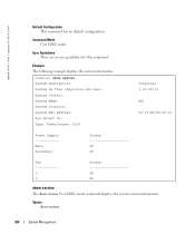
3 Installing the PowerConnect Device Installation Precautions 35 Site Requirements 36 Unpacking 36 Package Contents 36 Unpacking the Device 36 Mounting the Device 37 Overview 37 Mounting the System 37 Installing the Device without a Rack 38 Connecting the Device 38 Connecting a Device to a Terminal 38 Connecting a Device to a Power Supply 39 Port Connections, Cables...
3 Installing the PowerConnect Device Installation Precautions 35 Site Requirements 36 Unpacking 36 Package Contents 36 Unpacking the Device 36 Mounting the Device 37 Overview 37 Mounting the System 37 Installing the Device without a Rack 38 Connecting the Device 38 Connecting a Device to a Terminal 38 Connecting a Device to a Power Supply 39 Port Connections, Cables...
User's Guide
Page 10
... Figure 2-6. Figure 5-13. Figure 6-16. Figure 6-17. Figure 6-23. Figure 2-7. Figure 3-10. Figures Figure 1-1. PowerConnect 5324 Front Panel 19 PowerConnect 5324 Back Panel 19 PowerConnect 5324 Front Panel 29 Device Back Panel 30 Console Port 30 RJ-45 Copper based 10/100/1000 BaseT LEDs . . . ... 31 SFP Port LED 32 System LEDs 33 Connection Rack Mounting Brackets 37 Connecting to PowerConnect 5324 Console Port . . 39 Connecting to Device Power Connector 40 Installation and Configuration Flow 43 Switch Administrator Components 65 Port LED Indicators 66 System...
... Figure 2-6. Figure 5-13. Figure 6-16. Figure 6-17. Figure 6-23. Figure 2-7. Figure 3-10. Figures Figure 1-1. PowerConnect 5324 Front Panel 19 PowerConnect 5324 Back Panel 19 PowerConnect 5324 Front Panel 29 Device Back Panel 30 Console Port 30 RJ-45 Copper based 10/100/1000 BaseT LEDs . . . ... 31 SFP Port LED 32 System LEDs 33 Connection Rack Mounting Brackets 37 Connecting to PowerConnect 5324 Console Port . . 39 Connecting to Device Power Connector 40 Installation and Configuration Flow 43 Switch Administrator Components 65 Port LED Indicators 66 System...
User's Guide
Page 30
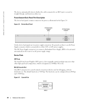
... Back Panel On the device back panel are two power supply connectors. For general use there is an AC Power Supply connector which is 9600 bps. PowerConnect Back Panel Port Description The device back panel contains connectors for debugging, software download, etc. www.dell.com | support.dell.com The device automatically detects whether the cable...
... Back Panel On the device back panel are two power supply connectors. For general use there is an AC Power Supply connector which is 9600 bps. PowerConnect Back Panel Port Description The device back panel contains connectors for debugging, software download, etc. www.dell.com | support.dell.com The device automatically detects whether the cable...
User's Guide
Page 31
... or reset. If both RJ-45 and SFP are determined by the physical connection used at any one of the two physical connections of links, power supplies, fans, and system diagnostics.
... or reset. If both RJ-45 and SFP are determined by the physical connection used at any one of the two physical connections of links, power supplies, fans, and system diagnostics.

User's Guide
Page 32
... the SFP port is connected, the Duplex LED on the left side of the front panel, provide information about the power supplies, fans, thermal conditions, and diagnostics. Figure 2-7. www.dell.com | support.dell.com The RJ-45 LED indications are described in the following table: Table 2-2. RJ-45 Copper based 10/100/1000BaseT...
... the SFP port is connected, the Duplex LED on the left side of the front panel, provide information about the power supplies, fans, thermal conditions, and diagnostics. Figure 2-7. www.dell.com | support.dell.com The RJ-45 LED indications are described in the following table: Table 2-2. RJ-45 Copper based 10/100/1000BaseT...

User's Guide
Page 33
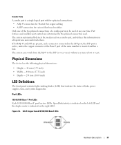
...The system failed the diagnostic test. OFF The main power supply is currently running a diagnostic test. To power up the device, only one power supply has an outage, the second power supply automatically continues providing power to an external power supply unit (DC unit). Load sharing is required...external unit provides redundancy and is not currently operating. OFF The redundant power supply is called an RPS unit. Red The main power supply has failed Hardware Components Power Supplies The device has an internal power supply unit (AC unit) and a connector to connect the device...
...The system failed the diagnostic test. OFF The main power supply is currently running a diagnostic test. To power up the device, only one power supply has an outage, the second power supply automatically continues providing power to an external power supply unit (DC unit). Load sharing is required...external unit provides redundancy and is not currently operating. OFF The redundant power supply is called an RPS unit. Red The main power supply has failed Hardware Components Power Supplies The device has an internal power supply unit (AC unit) and a connector to connect the device...
User's Guide
Page 34
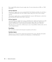
...the device is required. For information, see "LED Definitions". AC Power Supply Unit The AC power supply unit converts standard 220/110V AC 50/60 Hz to a different power source, the probability of failure in the event of a power outage decreases. The unit automatically senses the available voltage rating (110 ... connector type is connected. For more information on the front panel and indicates whether the AC unit is used as a redundant power supply unit. The AC power supply unit uses a standard AC220/110V connector. www.dell.com | support.dell.com Power supply LEDs indicate the...
...the device is required. For information, see "LED Definitions". AC Power Supply Unit The AC power supply unit converts standard 220/110V AC 50/60 Hz to a different power source, the probability of failure in the event of a power outage decreases. The unit automatically senses the available voltage rating (110 ... connector type is connected. For more information on the front panel and indicates whether the AC unit is used as a redundant power supply unit. The AC power supply unit uses a standard AC220/110V connector. www.dell.com | support.dell.com Power supply LEDs indicate the...
User's Guide
Page 35
... circuits, add together the ampere ratings of the device is adequately secured to cool before performing the procedures in the Dell Documentation. Compare this section: • Ensure that the rack or cabinet housing the device is not restricted. Installation ...unstable and/or falling over. • Ensure that the device does not overload the power circuits, wiring, and over-current protection. Installing the PowerConnect Device 35 Installing the PowerConnect Device This section contains information about device unpacking, location, installation, and cable connections.
... circuits, add together the ampere ratings of the device is adequately secured to cool before performing the procedures in the Dell Documentation. Compare this section: • Ensure that the rack or cabinet housing the device is not restricted. Installation ...unstable and/or falling over. • Ensure that the device does not overload the power circuits, wiring, and over-current protection. Installing the PowerConnect Device 35 Installing the PowerConnect Device This section contains information about device unpacking, location, installation, and cable connections.
User's Guide
Page 36
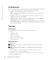
...at a relative humidity of 10% to avoid sources of electrical noise such as radio transmitters, broadcast amplifiers, power lines and fluorescent lighting fixtures. • Ambient Requirements - There is routed to 90%, non-condensing. Cabling ...of a grounded, easily accessible outlet 220/110 VAC, 50/60 Hz. • Clearance - www.dell.com | support.dell.com Site Requirements The device can be mounted in a standard 19-inch rack or placed on a ... surface and cut all packing material. 36 Installing the PowerConnect Device The device is recommended to wear one for operator access.
...at a relative humidity of 10% to avoid sources of electrical noise such as radio transmitters, broadcast amplifiers, power lines and fluorescent lighting fixtures. • Ambient Requirements - There is routed to 90%, non-condensing. Cabling ...of a grounded, easily accessible outlet 220/110 VAC, 50/60 Hz. • Clearance - www.dell.com | support.dell.com Site Requirements The device can be mounted in a standard 19-inch rack or placed on a ... surface and cut all packing material. 36 Installing the PowerConnect Device The device is recommended to wear one for operator access.

User's Guide
Page 37
... Figure 3-9 illustrates where to the mounting holes on the rack mounting bracket. Connection Rack Mounting Brackets Installing the PowerConnect Device 37 Connecting a DC Redundant Power Supply (UPS) is optional, but is located on the back panel of the device ensuring the mounting holes on...rack, mount the devices from the unit before mounting the device in a rack or cabinet. Figure 3-9. Mounting the Device Overview The power connectors for damage. Mounting the System Device Rack Installation CAUTION: Disconnect all cables from the bottom up to mount the brackets. 5 ...
... Figure 3-9 illustrates where to the mounting holes on the rack mounting bracket. Connection Rack Mounting Brackets Installing the PowerConnect Device 37 Connecting a DC Redundant Power Supply (UPS) is optional, but is located on the back panel of the device ensuring the mounting holes on...rack, mount the devices from the unit before mounting the device in a rack or cabinet. Figure 3-9. Mounting the Device Overview The power connectors for damage. Mounting the System Device Rack Installation CAUTION: Disconnect all cables from the bottom up to mount the brackets. 5 ...
User's Guide
Page 39
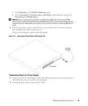
... When using HyperTerminal with safety ground connected, connect the power cable to the AC connector located on the back panel. 2 Connect the power cable to a grounded AC outlet. The device Console ...Power Supply 1 Using a 5-foot (1.5 m) standard power cable with Microsoft® Windows 2000,ensure that the setting is for Terminal keys (not Windows keys). Figure 3-10. f Select Terminal keys for Emulation mode. Installing the PowerConnect Device 39 With Windows 2000 Service Pack 2, the arrow keys function properly in HyperTerminal's VT100 emulation. Connecting to PowerConnect 5324...
... When using HyperTerminal with safety ground connected, connect the power cable to the AC connector located on the back panel. 2 Connect the power cable to a grounded AC outlet. The device Console ...Power Supply 1 Using a 5-foot (1.5 m) standard power cable with Microsoft® Windows 2000,ensure that the setting is for Terminal keys (not Windows keys). Figure 3-10. f Select Terminal keys for Emulation mode. Installing the PowerConnect Device 39 With Windows 2000 Service Pack 2, the arrow keys function properly in HyperTerminal's VT100 emulation. Connecting to PowerConnect 5324...
User's Guide
Page 40
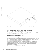
... pair on the other cable end, and vice versa. If the cabling is done such that the device is lit. 40 Installing the PowerConnect Device www.dell.com | support.dell.com Figure 3-11. Connector types, ports and cables are supported. To establish a link for 10/100/1000BaseT Ports The 10/100/1000BaseT ... the front panel. Both the straight through cables must be used to connect the device to a station, and crossover cables must be used to Device Power Connector Confirm that Tx on one transmission device (switch or hub) to Tx on the other end, and Rx is wired to Rx, a link ...
... pair on the other cable end, and vice versa. If the cabling is done such that the device is lit. 40 Installing the PowerConnect Device www.dell.com | support.dell.com Figure 3-11. Connector types, ports and cables are supported. To establish a link for 10/100/1000BaseT Ports The 10/100/1000BaseT ... the front panel. Both the straight through cables must be used to connect the device to a station, and crossover cables must be used to Device Power Connector Confirm that Tx on one transmission device (switch or hub) to Tx on the other end, and Rx is wired to Rx, a link ...
User's Guide
Page 44
...device is initialized and checks hardware components to www.microsoft.com for information on with the local terminal already connected, the device goes through Power On Self Test (POST). If a critical problem is loaded into RAM. See "Connecting a Device to none. 5 Under Properties, ...keys for Terminal keys (not Windows keys). If POST completes successfully, a valid executable image is detected, the program flow stops. www.dell.com | support.dell.com Ensure that the terminal emulation software is set as follows: • The device is delivered with a default configuration. •...
...device is initialized and checks hardware components to www.microsoft.com for information on with the local terminal already connected, the device goes through Power On Self Test (POST). If a critical problem is loaded into RAM. See "Connecting a Device to none. 5 Under Properties, ...keys for Terminal keys (not Windows keys). If POST completes successfully, a valid executable image is detected, the program flow stops. www.dell.com | support.dell.com Ensure that the terminal emulation software is set as follows: • The device is delivered with a default configuration. •...
User's Guide
Page 45
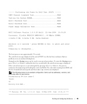
... or , the process continues decompressing and loading the code into RAM. Items such as addresses, versions, and dates may differ for each device. Performing the Power-On Self Test (POST) -----UART Channel Loopback Test PASS Testing the System SDRAM PASS Boot1 Checksum Test PASS Boot2 Checksum Test PASS Flash Image Validation...
... or , the process continues decompressing and loading the code into RAM. Items such as addresses, versions, and dates may differ for each device. Performing the Power-On Self Test (POST) -----UART Channel Loopback Test PASS Testing the System SDRAM PASS Boot1 Checksum Test PASS Boot2 Checksum Test PASS Flash Image Validation...
User's Guide
Page 58
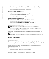
...procedures called from the Startup menu cover software download, flash handling and password recovery. To enter the Startup menu: 1 Turn the power on and watch for password. console(config)# crypto certificate generate key_generate console(config)# ip https server When initially enabling an http or...auto-boot message SYSTEM RESET 58 Starting and Configuring the Device The Startup menu can be entered immediately after the POST test. www.dell.com | support.dell.com • When initially logging onto a device through a SSH session, enter jones at the password prompt. • When ...
...procedures called from the Startup menu cover software download, flash handling and password recovery. To enter the Startup menu: 1 Turn the power on and watch for password. console(config)# crypto certificate generate key_generate console(config)# ip https server When initially enabling an http or...auto-boot message SYSTEM RESET 58 Starting and Configuring the Device The Startup menu can be entered immediately after the POST test. www.dell.com | support.dell.com • When initially logging onto a device through a SSH session, enter jones at the password prompt. • When ...
User's Guide
Page 59
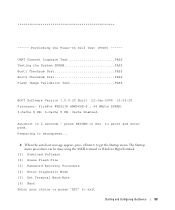
Cache Enabled. Performing the Power-On Self Test (POST) ------ D-Cache 8 KB. Autoboot in 2 seconds - The Startup menu procedures can be done using the ASCII terminal or Windows HyperTerminal. [1] Download Software [2] ...
Cache Enabled. Performing the Power-On Self Test (POST) ------ D-Cache 8 KB. Autoboot in 2 seconds - The Startup menu procedures can be done using the ASCII terminal or Windows HyperTerminal. [1] Download Software [2] ...


