User's Guide
Page 3
Contents 1 Introduction 11 System Description 11 PowerConnect 3524 11 PowerConnect 3524P 11 PowerConnect 3548 12 PowerConnect 3548P 12 Stacking Overview 12 Understanding the Stack Topology 13 Stacking Failover Topology 13 Stacking Members and Unit ID 13 Removing and Replacing Stacking Members 14 Exchanging Stacking Members 15 Switching from the Stack Master to the Backup Stack Master 17 Features Overview 17 IP Version 6 (IPv6) Support 17...
Contents 1 Introduction 11 System Description 11 PowerConnect 3524 11 PowerConnect 3524P 11 PowerConnect 3548 12 PowerConnect 3548P 12 Stacking Overview 12 Understanding the Stack Topology 13 Stacking Failover Topology 13 Stacking Members and Unit ID 13 Removing and Replacing Stacking Members 14 Exchanging Stacking Members 15 Switching from the Stack Master to the Backup Stack Master 17 Features Overview 17 IP Version 6 (IPv6) Support 17...

User's Guide
Page 4
... Console Port 29 Physical Dimensions 30 LED Definitions 30 Gigabit Port LEDs 32 System LEDs 33 Power Supplies 35 Stack ID Button 36 Reset Button 37 Ventilation System 37 3 Installing the PowerConnect 3524/P and PowerConnect 3548/P 39 Site Preparation 39 Unpacking 39 Package Contents 39 Unpacking the Device 40 Mounting the Device 40 Installing...
... Console Port 29 Physical Dimensions 30 LED Definitions 30 Gigabit Port LEDs 32 System LEDs 33 Power Supplies 35 Stack ID Button 36 Reset Button 37 Ventilation System 37 3 Installing the PowerConnect 3524/P and PowerConnect 3548/P 39 Site Preparation 39 Unpacking 39 Package Contents 39 Unpacking the Device 40 Mounting the Device 40 Installing...
User's Guide
Page 11
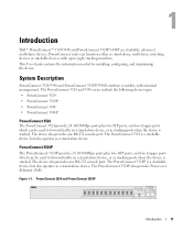
... as a stand-alone device. The PowerConnect 3524 is stacked. The device also provides one RS-232 console port. The PowerConnect 3524P is stacked. Introduction Dell™ PowerConnect™ 3524/3548 and PowerConnect 3524P/3548P are stackable, advanced multi-layer devices. System Description PowerConnect 3524/3548 and PowerConnect 3524P/3548P combine versatility with up to eight stacking members. PowerConnect 3524P The PowerConnect 3524P provides 24 10/100Mbps...
... as a stand-alone device. The PowerConnect 3524 is stacked. The device also provides one RS-232 console port. The PowerConnect 3524P is stacked. Introduction Dell™ PowerConnect™ 3524/3548 and PowerConnect 3524P/3548P are stackable, advanced multi-layer devices. System Description PowerConnect 3524/3548 and PowerConnect 3524P/3548P combine versatility with up to eight stacking members. PowerConnect 3524P The PowerConnect 3524P provides 24 10/100Mbps...

User's Guide
Page 12
... be used to forward traffic in stand-alone mode, or as stacking ports when the device is stacked. Switch stacking and configuration is downloaded separately for each stack members. PowerConnect 3548 and PowerConnect 3548P Stacking Overview PowerConnect 3524/P and PowerConnect 3548/P stacking provides multiple switch management through which can operate as stack members, and assigned a unique Unit ID. The device also provides one RS...
... be used to forward traffic in stand-alone mode, or as stacking ports when the device is stacked. Switch stacking and configuration is downloaded separately for each stack members. PowerConnect 3548 and PowerConnect 3548P Stacking Overview PowerConnect 3524/P and PowerConnect 3548/P stacking provides multiple switch management through which can operate as stack members, and assigned a unique Unit ID. The device also provides one RS...
User's Guide
Page 13
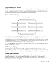
... connected to two neighboring devices, except for the top and bottom units. With the PowerConnect 3524/P and PowerConnect 3548/P stack, the system automatically switches to a Stacking Failover topology without interruption, and the Ring topology is where all devices in the stack accepts data and sends it to the device to which to each other forming a circle...
... connected to two neighboring devices, except for the top and bottom units. With the PowerConnect 3524/P and PowerConnect 3548/P stack, the system automatically switches to a Stacking Failover topology without interruption, and the Ring topology is where all devices in the stack accepts data and sends it to the device to which to each other forming a circle...
User's Guide
Page 15
... and the configuration files. For example, • If a PowerConnect 3524/P replaces PowerConnect 3524/P, all port configurations remain the same. • If a PowerConnect 3548/P replaces the PowerConnect 3548/P, all units in the stack. Exchanging Stacking Members If a stack member with the same Unit ID replaces an existing Unit ID .../or the ports are no longer present. Each port in the stack has a specific Unit ID, port type, and port number, which are physically present are displayed in the PowerConnect OpenManage Switch Administrator home page, and can be configured through the ...
... and the configuration files. For example, • If a PowerConnect 3524/P replaces PowerConnect 3524/P, all port configurations remain the same. • If a PowerConnect 3548/P replaces the PowerConnect 3548/P, all units in the stack. Exchanging Stacking Members If a stack member with the same Unit ID replaces an existing Unit ID .../or the ports are no longer present. Each port in the stack has a specific Unit ID, port type, and port number, which are physically present are displayed in the PowerConnect OpenManage Switch Administrator home page, and can be configured through the ...
User's Guide
Page 17
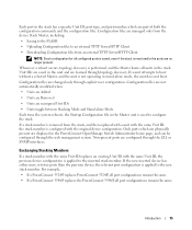
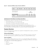
...in the following events occur: • The Stack Master fails or is removed from the stack. • Links from the Stack Master to the stacking members fails. • A soft switchover is synchronized between the Stack Master and the Backup Master results in a ...network infrastructure. Figure 1-6. The running on the Backup Master. PowerConnect 3548/P port replaces PowerConect 3524/P Port Same Configuration Same Configuration Switching from the Stack Master to the Backup Stack Master The Backup Master replaces the Stack Master if the following applications: • IP Phones &#...
...in the following events occur: • The Stack Master fails or is removed from the stack. • Links from the Stack Master to the stacking members fails. • A soft switchover is synchronized between the Stack Master and the Backup Master results in a ...network infrastructure. Figure 1-6. The running on the Backup Master. PowerConnect 3548/P port replaces PowerConect 3524/P Port Same Configuration Same Configuration Switching from the Stack Master to the Backup Stack Master The Backup Master replaces the Stack Master if the following applications: • IP Phones &#...
User's Guide
Page 28
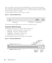
... ports • 2 Fiber ports - PowerConnect 3548 Front Panel 10/100 Base-T Ports 1, 3, 5, 7, ...47 System LEDs Reset Button Stacking Button Stacking LEDs 10/100 Base-T Ports 2, 4, 6, 8, ...48 G1 G2 1000Base-X SFP Ports G3 G4 Stacking Ports 28 Hardware Description On the front ...panel are two buttons on the front panel. PowerConnect 3548 Port Description The PowerConnect 3548 device is used to...
... ports • 2 Fiber ports - PowerConnect 3548 Front Panel 10/100 Base-T Ports 1, 3, 5, 7, ...47 System LEDs Reset Button Stacking Button Stacking LEDs 10/100 Base-T Ports 2, 4, 6, 8, ...48 G1 G2 1000Base-X SFP Ports G3 G4 Stacking Ports 28 Hardware Description On the front ...panel are two buttons on the front panel. PowerConnect 3548 Port Description The PowerConnect 3548 device is used to...
User's Guide
Page 29
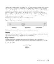
... panel surface, so reset by odd numbers 1-47, and the lower row of ports is used to select the unit number. PowerConnect 3548 Back Panel Console Port RPS Connector Power Connector The back panel contains an RPS connector, console port and power connector. Console Port ...In addition, the front panel also contains ports G1 - The following figure illustrates the PowerConnect 3548 back panel: Figure 2-4. SFP Ports The Small Form Factor Plugable (SFP) ports are fiber transceivers designated as stacking ports, or used for debugging, software download etc. They include TWSI (Two-Wire ...
... panel surface, so reset by odd numbers 1-47, and the lower row of ports is used to select the unit number. PowerConnect 3548 Back Panel Console Port RPS Connector Power Connector The back panel contains an RPS connector, console port and power connector. Console Port ...In addition, the front panel also contains ports G1 - The following figure illustrates the PowerConnect 3548 back panel: Figure 2-4. SFP Ports The Small Form Factor Plugable (SFP) ports are fiber transceivers designated as stacking ports, or used for debugging, software download etc. They include TWSI (Two-Wire ...
User's Guide
Page 32
... and PowerConnect 3548 RJ-45 Copper based 100BaseT LED Indications LED Link/Activity/Speed FDX Color Green Static Green Flashing Yellow Static Yellow Flashing OFF Green Static OFF Description The port is currently operating in the following table describes the Gigabit (stacking port) LEDs...is detected and is currently linked at normal load. The RJ-45 LED indications for PowerConnect 3524P and PowerConnect 3548P are described in Full Duplex mode. PowerConnect 3524P and PowerConnect 3548P RJ-45 Copper based 100BaseT LED Indications LED Color Description Speed/Link/Act Green Static The...
... and PowerConnect 3548 RJ-45 Copper based 100BaseT LED Indications LED Link/Activity/Speed FDX Color Green Static Green Flashing Yellow Static Yellow Flashing OFF Green Static OFF Description The port is currently operating in the following table describes the Gigabit (stacking port) LEDs...is detected and is currently linked at normal load. The RJ-45 LED indications for PowerConnect 3524P and PowerConnect 3548P are described in Full Duplex mode. PowerConnect 3524P and PowerConnect 3548P RJ-45 Copper based 100BaseT LED Indications LED Color Description Speed/Link/Act Green Static The...

User's Guide
Page 35
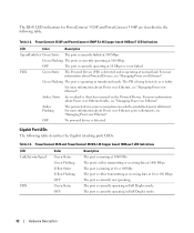
...stacking unit has one stacking LED lit, indicating its Unit ID number. Stacking LED Indications LED Color All Stacking LEDs OFF Stacking LED 1-8 (S1-S8) Green Static OFF Stacking Master LED Green Static OFF Description The switch is connected. The device is connected. The PowerConnect 3524/P and PowerConnect 3548.../P devices have an internal power supply of 470W (12V/-48V), with both power supply units is designated as Stacking Unit N. The AC power supply unit uses a standard...
...stacking unit has one stacking LED lit, indicating its Unit ID number. Stacking LED Indications LED Color All Stacking LEDs OFF Stacking LED 1-8 (S1-S8) Green Static OFF Stacking Master LED Green Static OFF Description The switch is connected. The device is connected. The PowerConnect 3524/P and PowerConnect 3548.../P devices have an internal power supply of 470W (12V/-48V), with both power supply units is designated as Stacking Unit N. The AC power supply unit uses a standard...
User's Guide
Page 37
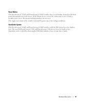
...of the switch is reset. The single reset circuit of the device. Reset Button The PowerConnect 3524/P and PowerConnect 3548/P switches have five built-in fans. If the Master device is reset, the entire stack is activated by observing the LED that indicates if one or more fans is reset,... the remain stacking members are not reset. If only a member unit is faulty. Hardware Description 37 The non-PoE PowerConnect 3524 and PowerConnect 3548 devices have two built-in fans. Operation can be verified by power-up or...
...of the switch is reset. The single reset circuit of the device. Reset Button The PowerConnect 3524/P and PowerConnect 3548/P switches have five built-in fans. If the Master device is reset, the entire stack is activated by observing the LED that indicates if one or more fans is reset,... the remain stacking members are not reset. If only a member unit is faulty. Hardware Description 37 The non-PoE PowerConnect 3524 and PowerConnect 3548 devices have two built-in fans. Operation can be verified by power-up or...
User's Guide
Page 44
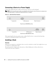
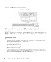
Back-Panel Power Connector Console Port RPS Connector Power Connector PowerConnect 3524/3548 Rear View Console Port EPS Connector PowerConnect 3524P/3548P Rear View Power Connector After connecting the device to the AC power connector on the back panel. All stacks must have a Master unit, and may have a Master Backup unit, with any other devices connected...
Back-Panel Power Connector Console Port RPS Connector Power Connector PowerConnect 3524/3548 Rear View Console Port EPS Connector PowerConnect 3524P/3548P Rear View Power Connector After connecting the device to the AC power connector on the back panel. All stacks must have a Master unit, and may have a Master Backup unit, with any other devices connected...
User's Guide
Page 45
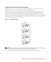
... device's port G3 in the stack to the devices without adding additional device accessories. Stacking Cable Diagram NOTE: In stacking mode ports designated as G3 and G4 are not displayed in the EWS. The effect is because the ports receive a different index for stacking. Installing the PowerConnect 3524/P and PowerConnect 3548/P 45 PowerConnect 35xx series systems switches use...
... device's port G3 in the stack to the devices without adding additional device accessories. Stacking Cable Diagram NOTE: In stacking mode ports designated as G3 and G4 are not displayed in the EWS. The effect is because the ports receive a different index for stacking. Installing the PowerConnect 3524/P and PowerConnect 3548/P 45 PowerConnect 35xx series systems switches use...
User's Guide
Page 46
..., and unit ID 3 to flash. The unit ID is manually configured by pressing the Stack ID button until the appropriate Stack ID LED is illuminated. 46 Installing the PowerConnect 3524/P and PowerConnect 3548/P When powering up, the configured LED number (corresponding to the previously saved unit ID) ...begins to 8 are for Member units. If the device is a stand-alone unit, the Stack LED is connected to a VT100 ...
..., and unit ID 3 to flash. The unit ID is manually configured by pressing the Stack ID button until the appropriate Stack ID LED is illuminated. 46 Installing the PowerConnect 3524/P and PowerConnect 3548/P When powering up, the configured LED number (corresponding to the previously saved unit ID) ...begins to 8 are for Member units. If the device is a stand-alone unit, the Stack LED is connected to a VT100 ...
User's Guide
Page 47
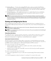
... or serial port 2) to connect to configure the device. The Stack ID button becomes unresponsive and the unit ID is configured. Installing the PowerConnect 3524/P and PowerConnect 3548/P 47 Pressing the Stack ID button again advances the Stack ID to the Device To configure the device, the device must ... device. NOTE: Before proceeding, read the release notes for each unit. Download the release notes from the Dell Support website at support.dell.com. When LED 8 is part of a stack, only one unit at a time until all external connections, connect a terminal to the device to the ...
... or serial port 2) to connect to configure the device. The Stack ID button becomes unresponsive and the unit ID is configured. Installing the PowerConnect 3524/P and PowerConnect 3548/P 47 Pressing the Stack ID button again advances the Stack ID to the Device To configure the device, the device must ... device. NOTE: Before proceeding, read the release notes for each unit. Download the release notes from the Dell Support website at support.dell.com. When LED 8 is part of a stack, only one unit at a time until all external connections, connect a terminal to the device to the ...
User's Guide
Page 48
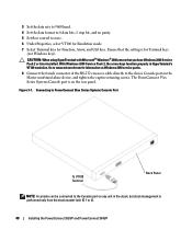
... port on any unit in HyperTerminal's VT100 emulation. The PowerConnect 35xx Series Systems Console port is performed only from the stack master (unit ID 1 or 2). 48 Installing the PowerConnect 3524/P and PowerConnect 3548/P With Windows 2000 Service Pack 2, the arrow keys function properly in the stack, but stack management is on the Master unit/stand-alone device...
... port on any unit in HyperTerminal's VT100 emulation. The PowerConnect 35xx Series Systems Console port is performed only from the stack master (unit ID 1 or 2). 48 Installing the PowerConnect 3524/P and PowerConnect 3548/P With Windows 2000 Service Pack 2, the arrow keys function properly in the stack, but stack management is on the Master unit/stand-alone device...


