User's Guide
Page 3
Contents 1 Introduction 11 System Description 11 PowerConnect 3524 11 PowerConnect 3524P 11 PowerConnect 3548 12 PowerConnect 3548P 12 Stacking Overview 12 Understanding the Stack Topology 13 Stacking Failover Topology 13 Stacking Members and Unit ID 13 Removing and Replacing Stacking Members 14 ...
Contents 1 Introduction 11 System Description 11 PowerConnect 3524 11 PowerConnect 3524P 11 PowerConnect 3548 12 PowerConnect 3548P 12 Stacking Overview 12 Understanding the Stack Topology 13 Stacking Failover Topology 13 Stacking Members and Unit ID 13 Removing and Replacing Stacking Members 14 ...

User's Guide
Page 4
... Port Description 27 The back panel contains an RPS connector, console port, and power connector 28 PowerConnect 3548 Port Description 28 SFP Ports 29 RS-232 Console Port 29 Physical Dimensions 30 LED Definitions 30 Gigabit Port LEDs 32 System LEDs... 33 Power Supplies 35 Stack ID Button 36 Reset Button 37 Ventilation System 37 3 Installing the PowerConnect 3524/P and PowerConnect 3548/P 39 Site Preparation 39 Unpacking 39 Package Contents 39 Unpacking the Device 40 Mounting the Device 40 Installing in a Rack 40 Installing on ...
... Port Description 27 The back panel contains an RPS connector, console port, and power connector 28 PowerConnect 3548 Port Description 28 SFP Ports 29 RS-232 Console Port 29 Physical Dimensions 30 LED Definitions 30 Gigabit Port LEDs 32 System LEDs... 33 Power Supplies 35 Stack ID Button 36 Reset Button 37 Ventilation System 37 3 Installing the PowerConnect 3524/P and PowerConnect 3548/P 39 Site Preparation 39 Unpacking 39 Package Contents 39 Unpacking the Device 40 Mounting the Device 40 Installing in a Rack 40 Installing on ...
User's Guide
Page 11
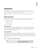
Introduction Dell™ PowerConnect™ 3524/3548 and PowerConnect 3524P/3548P are stackable, advanced multi-layer devices. The PowerConnect 3524 is a stackable device, but also operates as a stand-alone device. The PowerConnect 3524P is a stackable device, but also operates as stacking ports when the device is stacked. PowerConnect 3524P The PowerConnect 3524P provides 24 10/100Mbps ports plus two SFP...
Introduction Dell™ PowerConnect™ 3524/3548 and PowerConnect 3524P/3548P are stackable, advanced multi-layer devices. The PowerConnect 3524 is a stackable device, but also operates as a stand-alone device. The PowerConnect 3524P is a stackable device, but also operates as stacking ports when the device is stacked. PowerConnect 3524P The PowerConnect 3524P provides 24 10/100Mbps ports plus two SFP...

User's Guide
Page 12
... is selected as the Stack Master and another stacking member can be selected as a stand-alone device. PowerConnect 3548 The PowerConnect 3548 provides 48 10/100Mbps ports plus two SFP ports, and two Copper ports which the stack is managed from...Inter-unit Stacking Link Failure • Unit Insertion • Removal of a stack. In addition, PowerConnect 3548P provides PoE. PowerConnect 3548 and PowerConnect 3548P Stacking Overview PowerConnect 3524/P and PowerConnect 3548/P stacking provides multiple switch management through which can operate as stand-alone units. The stack is managed...
... is selected as the Stack Master and another stacking member can be selected as a stand-alone device. PowerConnect 3548 The PowerConnect 3548 provides 48 10/100Mbps ports plus two SFP ports, and two Copper ports which the stack is managed from...Inter-unit Stacking Link Failure • Unit Insertion • Removal of a stack. In addition, PowerConnect 3548P provides PoE. PowerConnect 3548 and PowerConnect 3548P Stacking Overview PowerConnect 3524/P and PowerConnect 3548/P stacking provides multiple switch management through which can operate as stand-alone units. The stack is managed...
User's Guide
Page 13
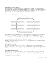
... devices, except for the top and bottom units. Each unit is severed. The operation mode is required. With the PowerConnect 3524/P and PowerConnect 3548/P stack, the system automatically switches to the stack without any system downtime. An SNMP message is automatically generated, but ...The Stack Master determines where the packets are essential to which to Stacking Failover Topology. Introduction 13 Understanding the Stack Topology The PowerConnect 35xx series systems operates in a chain formation. Each device in the stack are resolved, the device can be repaired to each...
... devices, except for the top and bottom units. Each unit is severed. The operation mode is required. With the PowerConnect 3524/P and PowerConnect 3548/P stack, the system automatically switches to the stack without any system downtime. An SNMP message is automatically generated, but ...The Stack Master determines where the packets are essential to which to Stacking Failover Topology. Introduction 13 Understanding the Stack Topology The PowerConnect 35xx series systems operates in a chain formation. Each device in the stack are resolved, the device can be repaired to each...
User's Guide
Page 15
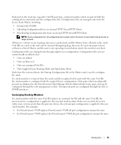
...are no longer present. Introduction 15 Non-present ports are changed only through explicit user configuration. Each port in the PowerConnect OpenManage Switch Administrator home page, and can be configured through the web management system. Whenever a reboot occurs, topology ... is applied to the inserted stack member. For example, • If a PowerConnect 3524/P replaces PowerConnect 3524/P, all port configurations remain the same. • If a PowerConnect 3548/P replaces the PowerConnect 3548/P, all units in the unit and are saved in the stack. Configuration files ...
...are no longer present. Introduction 15 Non-present ports are changed only through explicit user configuration. Each port in the PowerConnect OpenManage Switch Administrator home page, and can be configured through the web management system. Whenever a reboot occurs, topology ... is applied to the inserted stack member. For example, • If a PowerConnect 3524/P replaces PowerConnect 3524/P, all port configurations remain the same. • If a PowerConnect 3548/P replaces the PowerConnect 3548/P, all units in the unit and are saved in the stack. Configuration files ...
User's Guide
Page 16
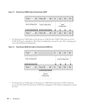
... default port configuration. PowerConnect 3548/P replaces PowerConnect 3548/P Same Configuration Same Configuration Same Configuration • If a PowerConnect 3548/P replaces PowerConnect 3524/P, the first 3548/P 24 FE ports receive the 3524/P 24 FE port configuration. The GE port configurations remain the same. PowerConnect 3524/P port replaces PowerConnect 3548/P port Same Configuration Same Configuration Default Configuration • If a PowerConnect 3524/P replaces PowerConnect 3548/P, the PowerConnect 3524/P 24...
... default port configuration. PowerConnect 3548/P replaces PowerConnect 3548/P Same Configuration Same Configuration Same Configuration • If a PowerConnect 3548/P replaces PowerConnect 3524/P, the first 3548/P 24 FE ports receive the 3524/P 24 FE port configuration. The GE port configurations remain the same. PowerConnect 3524/P port replaces PowerConnect 3548/P port Same Configuration Same Configuration Default Configuration • If a PowerConnect 3524/P replaces PowerConnect 3548/P, the PowerConnect 3524/P 24...
User's Guide
Page 17
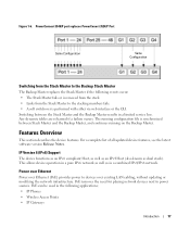
PowerConnect 3548/P port replaces PowerConect 3524/P Port Same Configuration Same Configuration Switching from the Stack Master to the stacking members fails. • A soft switchover is synchronized between ...
PowerConnect 3548/P port replaces PowerConect 3524/P Port Same Configuration Same Configuration Switching from the Stack Master to the stacking members fails. • A soft switchover is synchronized between ...
User's Guide
Page 28
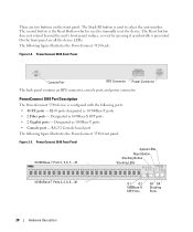
... front panel are two buttons on the front panel. PowerConnect 3548 Port Description The PowerConnect 3548 device is used to select the unit number. Designated as 10/100Base-T ports • 2 Fiber ports - PowerConnect 3524 Back Panel Console Port RPS Connector Power Connector The...1000Base-X SFP ports • 2 Gigabit ports - The following figure illustrates the PowerConnect 3524 back: Figure 2-2. Designated as 1000Base-T ports • Console port - There are all the device LEDs. PowerConnect 3548 Front Panel 10/100 Base-T Ports 1, 3, 5, 7, ...47 System LEDs Reset...
... front panel are two buttons on the front panel. PowerConnect 3548 Port Description The PowerConnect 3548 device is used to select the unit number. Designated as 10/100Base-T ports • 2 Fiber ports - PowerConnect 3524 Back Panel Console Port RPS Connector Power Connector The...1000Base-X SFP ports • 2 Gigabit ports - The following figure illustrates the PowerConnect 3524 back: Figure 2-2. Designated as 1000Base-T ports • Console port - There are all the device LEDs. PowerConnect 3548 Front Panel 10/100 Base-T Ports 1, 3, 5, 7, ...47 System LEDs Reset...
User's Guide
Page 29
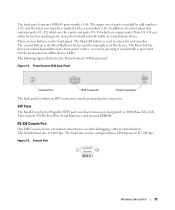
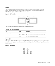
... by pressing it accidentally is used for debugging, software download etc. The Stack ID button is prevented. The following figure illustrates the PowerConnect 3548 back panel: Figure 2-4. They include TWSI (Two-Wire Serial Interface) and internal EPROM. G2 which is used to 115,200 bps.... PowerConnect 3548 Back Panel Console Port RPS Connector Power Connector The back panel contains an RPS connector, console port and power connector. In addition, ...
... by pressing it accidentally is used for debugging, software download etc. The Stack ID button is prevented. The following figure illustrates the PowerConnect 3548 back panel: Figure 2-4. They include TWSI (Two-Wire Serial Interface) and internal EPROM. G2 which is used to 115,200 bps.... PowerConnect 3548 Back Panel Console Port RPS Connector Power Connector The back panel contains an RPS connector, console port and power connector. In addition, ...
User's Guide
Page 30
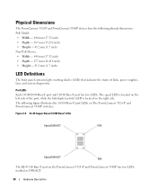
Physical Dimensions The PowerConnect 3524/P and PowerConnect 3548/P devices have the following figure illustrates the 10/100 Base-T port LEDs on the PowerConnect 3524 /P and PowerConnect 3548/P has two LEDs marked as LNK/ACT. 30 Hardware Description RJ-45 Copper Based 10/100 BaseT LEDs Speed/LNK/ACT FDX ...Speed/LNK/ACT FDX The RJ-45 100 Base-T port on The PowerConnect 3524 /P and PowerConnect 3548/P switches: Figure 2-6. The speed LED is located on the right side. Port LEDs Each 10/100/1000 Base-T port and 10/100...
Physical Dimensions The PowerConnect 3524/P and PowerConnect 3548/P devices have the following figure illustrates the 10/100 Base-T port LEDs on the PowerConnect 3524 /P and PowerConnect 3548/P has two LEDs marked as LNK/ACT. 30 Hardware Description RJ-45 Copper Based 10/100 BaseT LEDs Speed/LNK/ACT FDX ...Speed/LNK/ACT FDX The RJ-45 100 Base-T port on The PowerConnect 3524 /P and PowerConnect 3548/P switches: Figure 2-6. The speed LED is located on the right side. Port LEDs Each 10/100/1000 Base-T port and 10/100...
User's Guide
Page 31
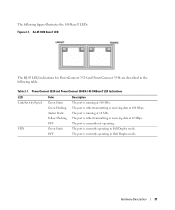
... data at 10 Mbs. The port is currently not operating. The port is currently operating in the following figure illustrates the 100 Base-T LEDs. PowerConnect 3524 and PowerConnect 3548 RJ-45 100BaseT LED Indications LED Link/Activity/Speed FDX Color Green Static Green Flashing Amber Static Yellow Flashing OFF Green Static OFF Description... The port is running at 100 Mbps. RJ-45 1000 BaseT LED The RJ-45 LED indications for PowerConnect 3524 and PowerConnect 3548 are described in Full Duplex mode. The following table: Table 2-1.
... data at 10 Mbs. The port is currently not operating. The port is currently operating in the following figure illustrates the 100 Base-T LEDs. PowerConnect 3524 and PowerConnect 3548 RJ-45 100BaseT LED Indications LED Link/Activity/Speed FDX Color Green Static Green Flashing Amber Static Yellow Flashing OFF Green Static OFF Description... The port is running at 100 Mbps. RJ-45 1000 BaseT LED The RJ-45 LED indications for PowerConnect 3524 and PowerConnect 3548 are described in Full Duplex mode. The following table: Table 2-1.
User's Guide
Page 32
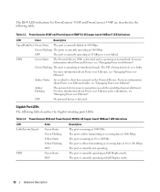
... Port LEDs The following table: Table 2-2. The port is currently operating in Half Duplex mode. 32 Hardware Description PowerConnect 3524P and PowerConnect 3548P RJ-45 Copper based 100BaseT LED Indications LED Color Description Speed/Link/Act Green Static The port is not linked.... allotments, see "Managing Power over Ethernet". For more information about Powered Devices, see "Managing Power over Ethernet". PowerConnect 3524 and PowerConnect 3548 RJ-45 Copper based 100BaseT LED Indications LED Link/Activity/Speed FDX Color Green Static Green Flashing Yellow Static Yellow ...
... Port LEDs The following table: Table 2-2. The port is currently operating in Half Duplex mode. 32 Hardware Description PowerConnect 3524P and PowerConnect 3548P RJ-45 Copper based 100BaseT LED Indications LED Color Description Speed/Link/Act Green Static The port is not linked.... allotments, see "Managing Power over Ethernet". For more information about Powered Devices, see "Managing Power over Ethernet". PowerConnect 3524 and PowerConnect 3548 RJ-45 Copper based 100BaseT LED Indications LED Link/Activity/Speed FDX Color Green Static Green Flashing Yellow Static Yellow ...
User's Guide
Page 33
... The SFP port LED indications are round in the following table: Table 2-4. On the PowerConnect 3524/P and PowerConnect 3548/P devices, the LEDs are located between ports and are described in shape. System LEDs The system LEDs of The PowerConnect 3524 /P and PowerConnect 3548/P devices provide information about the power supplies, fans, thermal conditions, and diagnostics. Figure...
... The SFP port LED indications are round in the following table: Table 2-4. On the PowerConnect 3524/P and PowerConnect 3548/P devices, the LEDs are located between ports and are described in shape. System LEDs The system LEDs of The PowerConnect 3524 /P and PowerConnect 3548/P devices provide information about the power supplies, fans, thermal conditions, and diagnostics. Figure...

User's Guide
Page 35
... regulated through load sharing. Table 2-6. Operation with a total of 370W for 24 ports PoE device. The PowerConnect 3524/P and PowerConnect 3548/P switches connect to an external EPS-470 unit to 63 Hz. Each stacking unit has one stacking LED ...supply unit (AC unit) and a connector to connect PowerConnect 3524/P and PowerConnect 3548/P devices to a PowerConnect EPS-470 unit, or to connect PowerConnect 3524 and PowerConnect 3548 devices to provide a redundant power option. The PowerConnect 3524/P and PowerConnect 3548/P devices have an internal power supply (12 Volt). The...
... regulated through load sharing. Table 2-6. Operation with a total of 370W for 24 ports PoE device. The PowerConnect 3524/P and PowerConnect 3548/P switches connect to an external EPS-470 unit to 63 Hz. Each stacking unit has one stacking LED ...supply unit (AC unit) and a connector to connect PowerConnect 3524/P and PowerConnect 3548/P devices to a PowerConnect EPS-470 unit, or to connect PowerConnect 3524 and PowerConnect 3548 devices to provide a redundant power option. The PowerConnect 3524/P and PowerConnect 3548/P devices have an internal power supply (12 Volt). The...
User's Guide
Page 37
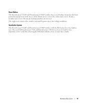
... with the PoE feature have five built-in fans. Hardware Description 37 The single reset circuit of the device. Reset Button The PowerConnect 3524/P and PowerConnect 3548/P switches have a reset button, located on the front panel, for manual reset of the switch is activated by observing the LED that indicates if one ... be verified by power-up or low-voltage conditions. If only a member unit is reset, the remain stacking members are not reset. The non-PoE PowerConnect 3524 and PowerConnect 3548 devices have two built-in fans.
... with the PoE feature have five built-in fans. Hardware Description 37 The single reset circuit of the device. Reset Button The PowerConnect 3524/P and PowerConnect 3548/P switches have a reset button, located on the front panel, for manual reset of the switch is activated by observing the LED that indicates if one ... be verified by power-up or low-voltage conditions. If only a member unit is reset, the remain stacking members are not reset. The non-PoE PowerConnect 3524 and PowerConnect 3548 devices have two built-in fans.
User's Guide
Page 39
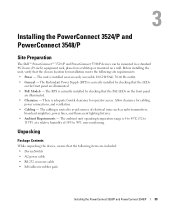
... is correctly installed by checking that the chosen location for installation meets the following items are illuminated. • Clearance - Installing the PowerConnect 3524/P and PowerConnect 3548/P Site Preparation The Dell™ PowerConnect™ 3524 /P and PowerConnect 3548/P devices can be mounted in a standard 48.26-am (19-inch) equipment rack, placed on a tabletop or mounted on the...
... is correctly installed by checking that the chosen location for installation meets the following items are illuminated. • Clearance - Installing the PowerConnect 3524/P and PowerConnect 3548/P Site Preparation The Dell™ PowerConnect™ 3524 /P and PowerConnect 3548/P devices can be mounted in a standard 48.26-am (19-inch) equipment rack, placed on a tabletop or mounted on the...

User's Guide
Page 40
...the box and place it on a secure and clean surface. 4 Remove all cables from the bottom up. 40 Installing the PowerConnect 3524/P and PowerConnect 3548/P Connecting a Redundant Power Supply (RPS) is optional, but is on the back panel. The RPS connector is recommended. ...The power connectors are positioned on devices connected to The PowerConnect 3524/P and PowerConnect 3548/P devices. Report any evidence of the devices. Installing in a Rack WARNING: Read the Safety Information included in a rack or...
...the box and place it on a secure and clean surface. 4 Remove all cables from the bottom up. 40 Installing the PowerConnect 3524/P and PowerConnect 3548/P Connecting a Redundant Power Supply (RPS) is optional, but is on the back panel. The RPS connector is recommended. ...The power connectors are positioned on devices connected to The PowerConnect 3524/P and PowerConnect 3548/P devices. Report any evidence of the devices. Installing in a Rack WARNING: Read the Safety Information included in a rack or...

User's Guide
Page 41
... the 48.26 cm (19 inch) rack, ensuring that the rack-mounting holes on the device line up to mount the brackets. Installing the PowerConnect 3524/P and PowerConnect 3548/P 41 Figure 3-1. Fasten the lower pair of screws before the upper pair of the device. 4 Insert the unit into the rack-mounting holes and...
... the 48.26 cm (19 inch) rack, ensuring that the rack-mounting holes on the device line up to mount the brackets. Installing the PowerConnect 3524/P and PowerConnect 3548/P 41 Figure 3-1. Fasten the lower pair of screws before the upper pair of the device. 4 Insert the unit into the rack-mounting holes and...

User's Guide
Page 42
... the process for the wall-mounting bracket on the other side of the device, ensuring that the ventilation holes are not obstructed. 42 Installing the PowerConnect 3524/P and PowerConnect 3548/P Bracket Installation for Mounting on a Wall 2 Insert the supplied screws into the rack-mounting holes and tighten with screws (not provided).
... the process for the wall-mounting bracket on the other side of the device, ensuring that the ventilation holes are not obstructed. 42 Installing the PowerConnect 3524/P and PowerConnect 3548/P Bracket Installation for Mounting on a Wall 2 Insert the supplied screws into the rack-mounting holes and tighten with screws (not provided).


