Command Line Interface Guide
Page 430
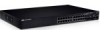
... of the remote host. The following example displays the system information. show system The show system [unit unit] • unit - Console> show system Unit ---1 2 3 4 5 Type --------PowerConnect 3524 PowerConnect 3524 PowerConnect 3524 PowerConnect 3524 PowerConnect 3524 430 System Management
... of the remote host. The following example displays the system information. show system The show system [unit unit] • unit - Console> show system Unit ---1 2 3 4 5 Type --------PowerConnect 3524 PowerConnect 3524 PowerConnect 3524 PowerConnect 3524 PowerConnect 3524 430 System Management

Command Line Interface Guide
Page 431
6 PowerConnect 3524 7 PowerConnect 3524 8 PowerConnect 3524 Unit 1 2 3 4 5 6 7 8 Main Power Supply ok ok ok ok ok ok ok ok Redundant Power Supply show version The show version [unit unit] • unit - Specifies the number of the unit. (Range: 1 - 6) Default Configuration This command has no user guidelines for this command. User Guidelines There are no default configuration. Syntax • show version User EXEC mode command displays system version information. System Management 431 Command Mode User EXEC mode.
6 PowerConnect 3524 7 PowerConnect 3524 8 PowerConnect 3524 Unit 1 2 3 4 5 6 7 8 Main Power Supply ok ok ok ok ok ok ok ok Redundant Power Supply show version The show version [unit unit] • unit - Specifies the number of the unit. (Range: 1 - 6) Default Configuration This command has no user guidelines for this command. User Guidelines There are no default configuration. Syntax • show version User EXEC mode command displays system version information. System Management 431 Command Mode User EXEC mode.
User's Guide
Page 3
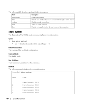
Contents 1 Introduction 11 System Description 11 PowerConnect 3524 11 PowerConnect 3524P 11 PowerConnect 3548 12 PowerConnect 3548P 12 Stacking Overview 12 Understanding the Stack Topology 13 Stacking Failover Topology 13 Stacking Members and Unit ID 13 Removing and Replacing Stacking Members ...
Contents 1 Introduction 11 System Description 11 PowerConnect 3524 11 PowerConnect 3524P 11 PowerConnect 3548 12 PowerConnect 3548P 12 Stacking Overview 12 Understanding the Stack Topology 13 Stacking Failover Topology 13 Stacking Members and Unit ID 13 Removing and Replacing Stacking Members ...

User's Guide
Page 4
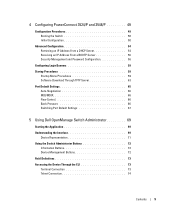
2 Hardware Description 27 Port Description 27 PowerConnect 3524 Port Description 27 The back panel contains an RPS connector, console port, and power connector 28 PowerConnect 3548 Port Description 28 SFP Ports 29 RS-232 Console Port 29 Physical Dimensions 30 LED Definitions 30 ...Gigabit Port LEDs 32 System LEDs 33 Power Supplies 35 Stack ID Button 36 Reset Button 37 Ventilation System 37 3 Installing the PowerConnect 3524/P and PowerConnect 3548/P 39 Site Preparation 39 Unpacking 39 Package Contents 39 Unpacking the Device 40 Mounting the Device 40 Installing in a Rack...
2 Hardware Description 27 Port Description 27 PowerConnect 3524 Port Description 27 The back panel contains an RPS connector, console port, and power connector 28 PowerConnect 3548 Port Description 28 SFP Ports 29 RS-232 Console Port 29 Physical Dimensions 30 LED Definitions 30 ...Gigabit Port LEDs 32 System LEDs 33 Power Supplies 35 Stack ID Button 36 Reset Button 37 Ventilation System 37 3 Installing the PowerConnect 3524/P and PowerConnect 3548/P 39 Site Preparation 39 Unpacking 39 Package Contents 39 Unpacking the Device 40 Mounting the Device 40 Installing in a Rack...
User's Guide
Page 5
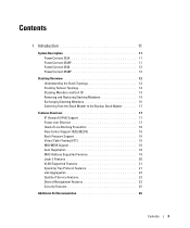
4 Configuring PowerConnect 3524/P and 3548/P 49 Configuration Procedures 49 Booting the Switch 50 Initial Configuration 50 Advanced Configuration 54 Retrieving an IP Address From a DHCP Server 54 Receiving ... TFTP Server 63 Port Default Settings 65 Auto-Negotiation 66 MDI/MDIX 66 Flow Control 66 Back Pressure 66 Switching Port Default Settings 67 5 Using Dell OpenManage Switch Administrator 69 Starting the Application 69 Understanding the Interface 69 Device Representation 71 Using the Switch Administrator Buttons 72 Information Buttons 72 Device...
4 Configuring PowerConnect 3524/P and 3548/P 49 Configuration Procedures 49 Booting the Switch 50 Initial Configuration 50 Advanced Configuration 54 Retrieving an IP Address From a DHCP Server 54 Receiving ... TFTP Server 63 Port Default Settings 65 Auto-Negotiation 66 MDI/MDIX 66 Flow Control 66 Back Pressure 66 Switching Port Default Settings 67 5 Using Dell OpenManage Switch Administrator 69 Starting the Application 69 Understanding the Interface 69 Device Representation 71 Using the Switch Administrator Buttons 72 Information Buttons 72 Device...
User's Guide
Page 11
... as stacking ports when the device is stacked. The PowerConnect 3524P also provides Power over Ethernet (PoE). PowerConnect 3524 and PowerConnect 3524P Introduction 11 The device also provides one RS-232 console port. The device also provides one RS-232 console port. Introduction Dell™ PowerConnect™ 3524/3548 and PowerConnect 3524P/3548P are stackable, advanced multi-layer devices. This User...
... as stacking ports when the device is stacked. The PowerConnect 3524P also provides Power over Ethernet (PoE). PowerConnect 3524 and PowerConnect 3524P Introduction 11 The device also provides one RS-232 console port. The device also provides one RS-232 console port. Introduction Dell™ PowerConnect™ 3524/3548 and PowerConnect 3524P/3548P are stackable, advanced multi-layer devices. This User...

User's Guide
Page 12
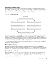
Figure 1-2. PowerConnect 3548 and PowerConnect 3548P Stacking Overview PowerConnect 3524/P and PowerConnect 3548/P stacking provides multiple switch management through a single point as if all units in a stand-alone device, or as stacking ports when...for each stack members. Switch software is managed from a: • Web-based interface • SNMP Management Station • Command Line Interface (CLI) PowerConnect 3524/P and PowerConnect 3548/P devices support stacking up to eight units per stack, or can operate as stand-alone units. However, all stack members are accessed through a ...
Figure 1-2. PowerConnect 3548 and PowerConnect 3548P Stacking Overview PowerConnect 3524/P and PowerConnect 3548/P stacking provides multiple switch management through a single point as if all units in a stand-alone device, or as stacking ports when...for each stack members. Switch software is managed from a: • Web-based interface • SNMP Management Station • Command Line Interface (CLI) PowerConnect 3524/P and PowerConnect 3548/P devices support stacking up to eight units per stack, or can operate as stand-alone units. However, all stack members are accessed through a ...
User's Guide
Page 13
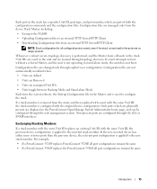
...restored. Figure 1-3. Introduction 13 The packet continues through the stack until it to the device to send traffic. With the PowerConnect 3524/P and PowerConnect 3548/P stack, the system automatically switches to a Stacking Failover topology without interruption, and the Ring topology is where all... Failover topology, devices operate in the boot-up process as a stand-alone device. Understanding the Stack Topology The PowerConnect 35xx series systems operates in the stacking topology, the stack reverts to the stacking configuration. Stacking Members and Unit ID...
...restored. Figure 1-3. Introduction 13 The packet continues through the stack until it to the device to send traffic. With the PowerConnect 3524/P and PowerConnect 3548/P stack, the system automatically switches to a Stacking Failover topology without interruption, and the Ring topology is where all... Failover topology, devices operate in the boot-up process as a stand-alone device. Understanding the Stack Topology The PowerConnect 35xx series systems operates in the stacking topology, the stack reverts to the stacking configuration. Stacking Members and Unit ID...
User's Guide
Page 15
... the stack has a specific Unit ID, port type, and port number, which are physically present are displayed in the PowerConnect OpenManage Switch Administrator home page, and can be configured through the CLI or SNMP interfaces. Configuration files are managed only from... inserted stack member. Unit IDs are saved in the stack. For example, • If a PowerConnect 3524/P replaces PowerConnect 3524/P, all port configurations remain the same. • If a PowerConnect 3548/P replaces the PowerConnect 3548/P, all units in the unit and are no longer present. Whenever a reboot occurs, topology ...
... the stack has a specific Unit ID, port type, and port number, which are physically present are displayed in the PowerConnect OpenManage Switch Administrator home page, and can be configured through the CLI or SNMP interfaces. Configuration files are managed only from... inserted stack member. Unit IDs are saved in the stack. For example, • If a PowerConnect 3524/P replaces PowerConnect 3524/P, all port configurations remain the same. • If a PowerConnect 3548/P replaces the PowerConnect 3548/P, all units in the unit and are no longer present. Whenever a reboot occurs, topology ...
User's Guide
Page 16
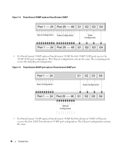
... remain the same. 16 Introduction PowerConnect 3548/P replaces PowerConnect 3548/P Same Configuration Same Configuration Same Configuration • If a PowerConnect 3548/P replaces PowerConnect 3524/P, the first 3548/P 24 FE ports receive the 3524/P 24 FE port configuration. PowerConnect 3524/P port replaces PowerConnect 3548/P port Same Configuration Same Configuration Default Configuration • If a PowerConnect 3524/P replaces PowerConnect 3548/P, the PowerConnect 3524/P 24 FE ports receives the...
... remain the same. 16 Introduction PowerConnect 3548/P replaces PowerConnect 3548/P Same Configuration Same Configuration Same Configuration • If a PowerConnect 3548/P replaces PowerConnect 3524/P, the first 3548/P 24 FE ports receive the 3524/P 24 FE port configuration. PowerConnect 3524/P port replaces PowerConnect 3548/P port Same Configuration Same Configuration Default Configuration • If a PowerConnect 3524/P replaces PowerConnect 3548/P, the PowerConnect 3524/P 24 FE ports receives the...
User's Guide
Page 27
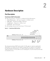
... G3 - RS-232 based port The following ports: • 24 Fast Ethernet ports - RJ-45 ports designated as 1000Base-T ports • Console port - PowerConnect 3524 Front Panel 10/100 Base-T Ports 1, 3, 5, 7, ...23 System LEDs Reset Button Stacking Button Stacking LEDs 10/100 Base-T Ports 2, 4, 6, 8, ...24...ports, or used to forward network traffic in a stand-alone device. G4 which are copper ports. Hardware Description Port Description PowerConnect 3524 Port Description The Dell™ PowerConnect™ 3524 device is marked with the following figure illustrates the...
... G3 - RS-232 based port The following ports: • 24 Fast Ethernet ports - RJ-45 ports designated as 1000Base-T ports • Console port - PowerConnect 3524 Front Panel 10/100 Base-T Ports 1, 3, 5, 7, ...23 System LEDs Reset Button Stacking Button Stacking LEDs 10/100 Base-T Ports 2, 4, 6, 8, ...24...ports, or used to forward network traffic in a stand-alone device. G4 which are copper ports. Hardware Description Port Description PowerConnect 3524 Port Description The Dell™ PowerConnect™ 3524 device is marked with the following figure illustrates the...
User's Guide
Page 28
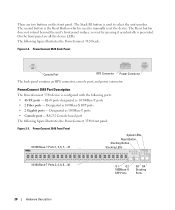
...designated as 1000Base-X SFP ports • 2 Gigabit ports - On the front panel are two buttons on the front panel. PowerConnect 3524 Back Panel Console Port RPS Connector Power Connector The back panel contains an RPS connector, console port, and power connector. RS...-232 Console based port The following figure illustrates the PowerConnect 3524 back: Figure 2-2. The following figure illustrates the PowerConnect 3548 front panel. PowerConnect 3548 Front Panel 10/100 Base-T Ports 1, 3, 5, 7, ...47 System LEDs Reset Button ...
...designated as 1000Base-X SFP ports • 2 Gigabit ports - On the front panel are two buttons on the front panel. PowerConnect 3524 Back Panel Console Port RPS Connector Power Connector The back panel contains an RPS connector, console port, and power connector. RS...-232 Console based port The following figure illustrates the PowerConnect 3524 back: Figure 2-2. The following figure illustrates the PowerConnect 3548 front panel. PowerConnect 3548 Front Panel 10/100 Base-T Ports 1, 3, 5, 7, ...47 System LEDs Reset Button ...
User's Guide
Page 30
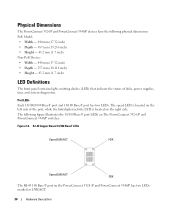
... The front panel contains light emitting diodes (LED) that indicate the status of the port, while the link/duplex/activity LED is located on The PowerConnect 3524 /P and PowerConnect 3548/P switches: Figure 2-6. RJ-45 Copper Based 10/100 BaseT LEDs Speed/LNK/ACT FDX Speed/LNK/ACT FDX The RJ-45 100 Base...-T port on the PowerConnect 3524 /P and PowerConnect 3548/P has two LEDs marked as LNK/ACT. 30 Hardware Description Port LEDs Each 10/100/1000 Base-T port and 10/100 Base-T port...
... The front panel contains light emitting diodes (LED) that indicate the status of the port, while the link/duplex/activity LED is located on The PowerConnect 3524 /P and PowerConnect 3548/P switches: Figure 2-6. RJ-45 Copper Based 10/100 BaseT LEDs Speed/LNK/ACT FDX Speed/LNK/ACT FDX The RJ-45 100 Base...-T port on the PowerConnect 3524 /P and PowerConnect 3548/P has two LEDs marked as LNK/ACT. 30 Hardware Description Port LEDs Each 10/100/1000 Base-T port and 10/100 Base-T port...
User's Guide
Page 31
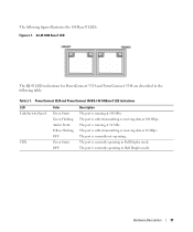
The port is running at 100 Mbs. PowerConnect 3524 and PowerConnect 3548 RJ-45 100BaseT LED Indications LED Link/Activity/Speed FDX Color Green Static Green Flashing Amber Static Yellow Flashing OFF Green Static OFF Description ... operating in the following figure illustrates the 100 Base-T LEDs. The following table: Table 2-1. RJ-45 1000 BaseT LED The RJ-45 LED indications for PowerConnect 3524 and PowerConnect 3548 are described in Full Duplex mode.
The port is running at 100 Mbs. PowerConnect 3524 and PowerConnect 3548 RJ-45 100BaseT LED Indications LED Link/Activity/Speed FDX Color Green Static Green Flashing Amber Static Yellow Flashing OFF Green Static OFF Description ... operating in the following figure illustrates the 100 Base-T LEDs. The following table: Table 2-1. RJ-45 1000 BaseT LED The RJ-45 LED indications for PowerConnect 3524 and PowerConnect 3548 are described in Full Duplex mode.
User's Guide
Page 32
... or is operating at 10 or 100 Mbps. Amber Flashing The powered device power conception exceeds the predefined power allotment. PowerConnect 3524 and PowerConnect 3548 RJ-45 Copper based 100BaseT LED Indications LED Link/Activity/Speed FDX Color Green Static Green Flashing Yellow Static Yellow ...is running at 10 or 100Mbs. The port is currently operating in Full Duplex mode. The RJ-45 LED indications for PowerConnect 3524P and PowerConnect 3548P are described in Half Duplex mode. 32 Hardware Description For more information about Power over Ethernet, see "Managing Power ...
... or is operating at 10 or 100 Mbps. Amber Flashing The powered device power conception exceeds the predefined power allotment. PowerConnect 3524 and PowerConnect 3548 RJ-45 Copper based 100BaseT LED Indications LED Link/Activity/Speed FDX Color Green Static Green Flashing Yellow Static Yellow ...is running at 10 or 100Mbs. The port is currently operating in Full Duplex mode. The RJ-45 LED indications for PowerConnect 3524P and PowerConnect 3548P are described in Half Duplex mode. 32 Hardware Description For more information about Power over Ethernet, see "Managing Power ...
User's Guide
Page 33
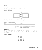
... conditions, and diagnostics. The following table: Table 2-4. OFF The port is currently transmitting or receiving data. Figure 2-8. System LEDs Hardware Description 33 On the PowerConnect 3524/P and PowerConnect 3548/P devices, the LEDs are located between ports and are described in shape. Green Flashing The port is currently not linked. Figure 2-9. SFP Port LED...
... conditions, and diagnostics. The following table: Table 2-4. OFF The port is currently transmitting or receiving data. Figure 2-8. System LEDs Hardware Description 33 On the PowerConnect 3524/P and PowerConnect 3548/P devices, the LEDs are located between ports and are described in shape. Green Flashing The port is currently not linked. Figure 2-9. SFP Port LED...

User's Guide
Page 35
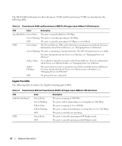
... Supplies The device has an internal power supply unit (AC unit) and a connector to connect PowerConnect 3524/P and PowerConnect 3548/P devices to a PowerConnect EPS-470 unit, or to connect PowerConnect 3524 and PowerConnect 3548 devices to provide a redundant power option. Table 2-6. AC Power Supply Unit The AC power...connected. Hardware Description 35 LED indicator is on the front panel and indicates whether the AC unit is required. The PowerConnect 3524/P and PowerConnect 3548/P switches connect to an external EPS-470 unit to 63 Hz. Each stacking unit has one stacking LED lit...
... Supplies The device has an internal power supply unit (AC unit) and a connector to connect PowerConnect 3524/P and PowerConnect 3548/P devices to a PowerConnect EPS-470 unit, or to connect PowerConnect 3524 and PowerConnect 3548 devices to provide a redundant power option. Table 2-6. AC Power Supply Unit The AC power...connected. Hardware Description 35 LED indicator is on the front panel and indicates whether the AC unit is required. The PowerConnect 3524/P and PowerConnect 3548/P switches connect to an external EPS-470 unit to 63 Hz. Each stacking unit has one stacking LED lit...
User's Guide
Page 37
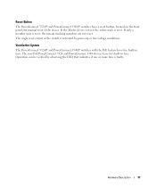
... is reset, the remain stacking members are not reset. Ventilation System The PowerConnect 3524/P and PowerConnect 3548/P switches with the PoE feature have two built-in fans. The non-PoE PowerConnect 3524 and PowerConnect 3548 devices have five built-in fans. Reset Button The PowerConnect 3524/P and PowerConnect 3548/P switches have a reset button, located on the front panel, for...
... is reset, the remain stacking members are not reset. Ventilation System The PowerConnect 3524/P and PowerConnect 3548/P switches with the PoE feature have two built-in fans. The non-PoE PowerConnect 3524 and PowerConnect 3548 devices have five built-in fans. Reset Button The PowerConnect 3524/P and PowerConnect 3548/P switches have a reset button, located on the front panel, for...
User's Guide
Page 39
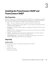
... Redundant Power Supply (RPS) is installed near an easily accessible 100-240 VAC, 50-60 Hz outlet. • General - Installing the PowerConnect 3524/P and PowerConnect 3548/P Site Preparation The Dell™ PowerConnect™ 3524 /P and PowerConnect 3548/P devices can be mounted in a standard 48.26-am (19-inch) equipment rack, placed on a tabletop or mounted on the...
... Redundant Power Supply (RPS) is installed near an easily accessible 100-240 VAC, 50-60 Hz outlet. • General - Installing the PowerConnect 3524/P and PowerConnect 3548/P Site Preparation The Dell™ PowerConnect™ 3524 /P and PowerConnect 3548/P devices can be mounted in a standard 48.26-am (19-inch) equipment rack, placed on a tabletop or mounted on the...

User's Guide
Page 40
...the box and place it on a secure and clean surface. 4 Remove all cables from the bottom up. 40 Installing the PowerConnect 3524/P and PowerConnect 3548/P • Rack-mount kit for rack installation or wall mounting kit • Documentation CD • Product Information Guide... immediately. WARNING: Disconnect all packing material. 5 Inspect the device and accessories for safety information on devices connected to The PowerConnect 3524/P and PowerConnect 3548/P devices. Installing in a Rack WARNING: Read the Safety Information included in a rack or cabinet. The RPS connector...
...the box and place it on a secure and clean surface. 4 Remove all cables from the bottom up. 40 Installing the PowerConnect 3524/P and PowerConnect 3548/P • Rack-mount kit for rack installation or wall mounting kit • Documentation CD • Product Information Guide... immediately. WARNING: Disconnect all packing material. 5 Inspect the device and accessories for safety information on devices connected to The PowerConnect 3524/P and PowerConnect 3548/P devices. Installing in a Rack WARNING: Read the Safety Information included in a rack or cabinet. The RPS connector...


