
User's Guide
Page 3
... Description 12 PowerConnect 3324/3348 Stacking Overview 12 Stack Members and Unit ID 13 Configuration Handling 14 Rearranging Stacks 15 Replacing Stack Members 15 PowerConnect User Guide Overview 17 Installing the PowerConnect 3324/3348 Switch 17 Using the Dell OpenManage Switch Administrator 17 PowerConnect 3324/3348 CLI Documentation 18 2 Hardware Description PowerConnect 3324/3348 Description 20 PowerConnect 3324/3348 Dimensions 20 PowerConnect 3324/3348 Rear Panel 20 PowerConnect 3324/3348...
... Description 12 PowerConnect 3324/3348 Stacking Overview 12 Stack Members and Unit ID 13 Configuration Handling 14 Rearranging Stacks 15 Replacing Stack Members 15 PowerConnect User Guide Overview 17 Installing the PowerConnect 3324/3348 Switch 17 Using the Dell OpenManage Switch Administrator 17 PowerConnect 3324/3348 CLI Documentation 18 2 Hardware Description PowerConnect 3324/3348 Description 20 PowerConnect 3324/3348 Dimensions 20 PowerConnect 3324/3348 Rear Panel 20 PowerConnect 3324/3348...
User's Guide
Page 4
...31 Package Contents 31 Unpacking 31 Device Rack Installation 32 Installing the Switch without a Rack 32 Stacking PowerConnect 3324/3348 33 Connecting Stacking Cables 33 Connecting the PowerConnect 3324/3348 to a Power Supply 34 Cable, Port, and Pinout Information 35 Port Connections 36 ...Cable Connections 38 4 Configuring the PowerConnect 3324/3348 Switch Configuration Overview 42 General Configuration Information 43 Auto-...
...31 Package Contents 31 Unpacking 31 Device Rack Installation 32 Installing the Switch without a Rack 32 Stacking PowerConnect 3324/3348 33 Connecting Stacking Cables 33 Connecting the PowerConnect 3324/3348 to a Power Supply 34 Cable, Port, and Pinout Information 35 Port Connections 36 ...Cable Connections 38 4 Configuring the PowerConnect 3324/3348 Switch Configuration Overview 42 General Configuration Information 43 Auto-...
User's Guide
Page 5
...Running the Management Station 68 Telnet access 70 Web Access (HTTP server 72 Configuring Stacking 75 Stacking Introduction 75 Stacking Requirements 75 Configuring a Stack 75 Expanding the Stack 76 Rebooting the Device 76 Startup Menu Functions 77 Downloading the Software 77 Erasing ... 80 Running Diagnostics 80 Downloading the Software to Stacking Units 80 Downloading the Software Sequentially Using the CLI . . . . . 81 Downloading the Software Individually Using the CLI 82 Downloading the Software Via the PowerConnect 3324/3348 Dell OpenManage Switch Administrator 84 Contents 5
...Running the Management Station 68 Telnet access 70 Web Access (HTTP server 72 Configuring Stacking 75 Stacking Introduction 75 Stacking Requirements 75 Configuring a Stack 75 Expanding the Stack 76 Rebooting the Device 76 Startup Menu Functions 77 Downloading the Software 77 Erasing ... 80 Running Diagnostics 80 Downloading the Software to Stacking Units 80 Downloading the Software Sequentially Using the CLI . . . . . 81 Downloading the Software Individually Using the CLI 82 Downloading the Software Via the PowerConnect 3324/3348 Dell OpenManage Switch Administrator 84 Contents 5
User's Guide
Page 12
... console. PowerConnect 3324/3348 Stacking Overview PowerConnect 3324/3348 stacking provides multiple device management through which the entire stack is managed. PowerConnect 3324/3348 can be used as standalone units. 12 Over view When operating as a stand-alone unit, the PowerConnect 3324/3348 stacking ports can also operate as Giga Ethernet ports. www.dell.com | support.dell.com System Description The Dell™ PowerConnect™ 3324 and...
... console. PowerConnect 3324/3348 Stacking Overview PowerConnect 3324/3348 stacking provides multiple device management through which the entire stack is managed. PowerConnect 3324/3348 can be used as standalone units. 12 Over view When operating as a stand-alone unit, the PowerConnect 3324/3348 stacking ports can also operate as Giga Ethernet ports. www.dell.com | support.dell.com System Description The Dell™ PowerConnect™ 3324 and...
User's Guide
Page 13
... by the network administrator as the stack master, while all stacking LEDs are centralized. If the stacking module is displayed on the master unit. PowerConnect 3324/3348 stacking architecture provides dynamic learning for the stack to the stacking configuration. Applications running in port G1...ID. Device software is essential to operate. The Unit ID is downloaded separately for the entire stack runs on the console. PowerConnect 3324/3348 stacks provide across-the-stack Layer 2 functionality including: • Switching • Trunking • Port Mirroring • ...
... by the network administrator as the stack master, while all stacking LEDs are centralized. If the stacking module is displayed on the master unit. PowerConnect 3324/3348 stacking architecture provides dynamic learning for the stack to the stacking configuration. Applications running in port G1...ID. Device software is essential to operate. The Unit ID is downloaded separately for the entire stack runs on the console. PowerConnect 3324/3348 stacks provide across-the-stack Layer 2 functionality including: • Switching • Trunking • Port Mirroring • ...

User's Guide
Page 14
... is configured with the same Unit ID, or a master unit is written in the Dell OpenManage™ Switch Administrator and can be configured through the CLI or SNMP interfaces. 14 Over view If a PowerConnect 3324/3348 stack member is part of both the configuration commands and the configuration files. Configuration files are configured through...
... is configured with the same Unit ID, or a master unit is written in the Dell OpenManage™ Switch Administrator and can be configured through the CLI or SNMP interfaces. 14 Over view If a PowerConnect 3324/3348 stack member is part of both the configuration commands and the configuration files. Configuration files are configured through...
User's Guide
Page 15
... by either more than the previous device, the relevant port configuration is established not by the physical order of the stack members but initialized according to the new stack member. For example: • If a PowerConnect 3324 replaces a PowerConnect 3324, the new 24 10/100 BaseT ports receive the previous 24 10/100 BaseT port configuration. The...
... by either more than the previous device, the relevant port configuration is established not by the physical order of the stack members but initialized according to the new stack member. For example: • If a PowerConnect 3324 replaces a PowerConnect 3324, the new 24 10/100 BaseT ports receive the previous 24 10/100 BaseT port configuration. The...
User's Guide
Page 20
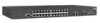
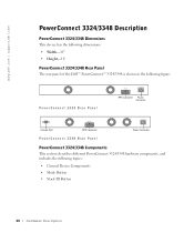
www.dell.com | support.dell.com PowerConnect 3324/3348 Description PowerConnect 3324/3348 Dimensions This device has the following dimensions: • Width-19" • Height-1U PowerConnect 3324/3348 Rear Panel The rear panel of the Dell™ PowerConnect™ 3324/3348 is shown in the following topics: • General Device Components • Mode Button • Stack ID Button 20 H a r d w a r e D e s c r i p t i o n DC RPS Connector...
www.dell.com | support.dell.com PowerConnect 3324/3348 Description PowerConnect 3324/3348 Dimensions This device has the following dimensions: • Width-19" • Height-1U PowerConnect 3324/3348 Rear Panel The rear panel of the Dell™ PowerConnect™ 3324/3348 is shown in the following topics: • General Device Components • Mode Button • Stack ID Button 20 H a r d w a r e D e s c r i p t i o n DC RPS Connector...

User's Guide
Page 21
General Device Components The PowerConnect 3324/3348 includes the following hardware components: • CPU-Based on Motorola's MPC 8245. • FLASH-Contains 8 MB of FLASH Memory. • SDRAM-Contains 32 MB. Stack ID Button 123 Stacking LEDs 456 1 3 5 7 9 11 2 4 6 8 10 12 13 15 17 19 21 23 14 16 18 20 22 24... 1 3 5 7 9 11 2 4 6 8 10 12 13 15 17 19 21 23 14 16 18 20 22 24 PowerConnect 3324 Front Panel G1 G2 123 456 Stacking LEDs 123 Stack ID Button 456 G1 G2 1 3 5 7 9 11 2 4 6 8 10 12 13 15 17 19 21 23 14 16...
General Device Components The PowerConnect 3324/3348 includes the following hardware components: • CPU-Based on Motorola's MPC 8245. • FLASH-Contains 8 MB of FLASH Memory. • SDRAM-Contains 32 MB. Stack ID Button 123 Stacking LEDs 456 1 3 5 7 9 11 2 4 6 8 10 12 13 15 17 19 21 23 14 16 18 20 22 24... 1 3 5 7 9 11 2 4 6 8 10 12 13 15 17 19 21 23 14 16 18 20 22 24 PowerConnect 3324 Front Panel G1 G2 123 456 Stacking LEDs 123 Stack ID Button 456 G1 G2 1 3 5 7 9 11 2 4 6 8 10 12 13 15 17 19 21 23 14 16...
User's Guide
Page 22
... be selected within 15 seconds after booting the device. The Stack module is the upper connection point. www.dell.com | support.dell.com Mode Button The Mode Button toggles between port activity and port duplex settings. Stack ID Button The PowerConnect 3324/3348 front panel contains a Stack ID button that permits network administrators to manually select the...
... be selected within 15 seconds after booting the device. The Stack module is the upper connection point. www.dell.com | support.dell.com Mode Button The Mode Button toggles between port activity and port duplex settings. Stack ID Button The PowerConnect 3324/3348 front panel contains a Stack ID button that permits network administrators to manually select the...

User's Guide
Page 23
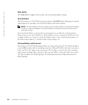
Hardware Description 23 Master Unit #1 Tx Rx Member Unit #1 Tx Rx Member Unit #2 Tx Rx Member Unit #3 Tx Rx Stacking Connections For more information about connecting Stacking cables, see "Connecting Stacking Cables".
Hardware Description 23 Master Unit #1 Tx Rx Member Unit #1 Tx Rx Member Unit #2 Tx Rx Member Unit #3 Tx Rx Stacking Connections For more information about connecting Stacking cables, see "Connecting Stacking Cables".

User's Guide
Page 24
...All RS232 pins are as follows: • Port LEDs • System LEDs • Stacking LEDs 24 H a r d w a r e D e s c r i p t i o n Each combo port is enabled, PowerConnect 3324/3348 automatically detects and corrects the difference between crossover and straight-through cables on all ports. ...one of the two physical connections of port links and modes, power supply status, stacking status, and system diagnostics. www.dell.com | support.dell.com Ports Description Ethernet Port Description The PowerConnect 3324 features 24 FE 10BaseT/100BaseTX UTP copper RJ45 ports per unit and 2 combo ports...
...All RS232 pins are as follows: • Port LEDs • System LEDs • Stacking LEDs 24 H a r d w a r e D e s c r i p t i o n Each combo port is enabled, PowerConnect 3324/3348 automatically detects and corrects the difference between crossover and straight-through cables on all ports. ...one of the two physical connections of port links and modes, power supply status, stacking status, and system diagnostics. www.dell.com | support.dell.com Ports Description Ethernet Port Description The PowerConnect 3324 features 24 FE 10BaseT/100BaseTX UTP copper RJ45 ports per unit and 2 combo ports...

User's Guide
Page 27
...Mbps. Port link up with activity. The status of each of the power supplies, diagnostic mode, and stack mode as follows: LED PWR RPS Diag Stack Color Green Amber Green Amber Off Green Activity Static Static Static Static Off Flashing Green Off Static Off ... . Redundant power supply operational. For an explanation of the port LEDs in the Diagnostic mode. Power supply failure. Stacking successfully completed. Power, Diagnostic, and Stack LEDs Hardware Description 27 Redundant power supply failure. The system is used to the system LEDs is currently in each ...
...Mbps. Port link up with activity. The status of each of the power supplies, diagnostic mode, and stack mode as follows: LED PWR RPS Diag Stack Color Green Amber Green Amber Off Green Activity Static Static Static Static Off Flashing Green Off Static Off ... . Redundant power supply operational. For an explanation of the port LEDs in the Diagnostic mode. Power supply failure. Stacking successfully completed. Power, Diagnostic, and Stack LEDs Hardware Description 27 Redundant power supply failure. The system is used to the system LEDs is currently in each ...

User's Guide
Page 28
Each unit in the stack has one of this section, the stacking LEDs are numbered 1 through 6 is lit, the unit is the master unit. As shown in the stack. www.dell.com | support.dell.com Stacking LEDs The stacking LEDs indicate the unit's position in the stack. When stacking LED 1 is lit, the unit is the corresponding stacking member unit. 28 H a r d w a r e D e s c r i p t i o n When one stacking LED lit, indicating its position in the front panel illustrations at the start of the stacking LEDs numbered 2 through 6.
Each unit in the stack has one of this section, the stacking LEDs are numbered 1 through 6 is lit, the unit is the master unit. As shown in the stack. www.dell.com | support.dell.com Stacking LEDs The stacking LEDs indicate the unit's position in the stack. When stacking LED 1 is lit, the unit is the corresponding stacking member unit. 28 H a r d w a r e D e s c r i p t i o n When one stacking LED lit, indicating its position in the front panel illustrations at the start of the stacking LEDs numbered 2 through 6.

User's Guide
Page 33
... 24-port and 48-port devices can be stacked with a Stack Module connected to the selected member upper TX port. 4 Connect the stack in the SFP slot. Connecting Stacking Cables 1 Place each G2 port. Installing the PowerConnect 3324/3348 Switch 33 Stacking PowerConnect 3324/3348 PowerConnect 3324/3348 supports stacking up to six PowerConnect 3324/3348 devices or up to 192 Fast Ethernet ports...
... 24-port and 48-port devices can be stacked with a Stack Module connected to the selected member upper TX port. 4 Connect the stack in the SFP slot. Connecting Stacking Cables 1 Place each G2 port. Installing the PowerConnect 3324/3348 Switch 33 Stacking PowerConnect 3324/3348 PowerConnect 3324/3348 supports stacking up to six PowerConnect 3324/3348 devices or up to 192 Fast Ethernet ports...

User's Guide
Page 34
The PowerConnect 3324/3348 is supplied with power from: • AC power supply source. • An optional PowerConnect RPS-600 redundant power supply. • Both AC and DC sources. 34 I n s t a llin g t h e Po we rC on configuring stacks, see "Configuring Stacking". www.dell.com | support.dell.com Connected Stack For more information on n e c t 3324/3348 Sw itc h Connecting the PowerConnect 3324/3348 to a Power Supply The following section contains instruction for connecting the PowerConnect 3324/3348 to a AC power connection.
The PowerConnect 3324/3348 is supplied with power from: • AC power supply source. • An optional PowerConnect RPS-600 redundant power supply. • Both AC and DC sources. 34 I n s t a llin g t h e Po we rC on configuring stacks, see "Configuring Stacking". www.dell.com | support.dell.com Connected Stack For more information on n e c t 3324/3348 Sw itc h Connecting the PowerConnect 3324/3348 to a Power Supply The following section contains instruction for connecting the PowerConnect 3324/3348 to a AC power connection.

User's Guide
Page 41
SECTION 4 Configuring the PowerConnect 3324/3348 Switch Configuration Overview General Configuration Information Terminal Connection Configuration Other Configuration Requirements Booting the Device Device Configuration Introduction Initial Configuration Advanced Configuration Sample Configuration Process Configuring Stacking Rebooting the Device Startup Menu Functions Downloading the Software to Stacking Units Defining SNMP Settings Connecting Devices
SECTION 4 Configuring the PowerConnect 3324/3348 Switch Configuration Overview General Configuration Information Terminal Connection Configuration Other Configuration Requirements Booting the Device Device Configuration Introduction Initial Configuration Advanced Configuration Sample Configuration Process Configuring Stacking Rebooting the Device Startup Menu Functions Downloading the Software to Stacking Units Defining SNMP Settings Connecting Devices

User's Guide
Page 42
www.dell.com | support.dell.com Configuration Overview This section describes the initial device configuration and includes: • Initial Device Bootup • Preliminary Configuration Requirements • Configuring Stacking After all the device external connections are illustrated in place, a terminal must be connected to the device to monitor the boot and other procedures. The order of installation and configuration procedures are in the following flowchart: 42 C o n f i g u r i n g t h e Po w e r C o n n e c t 3 3 2 4 / 3 3 4 8 S w i t c h
www.dell.com | support.dell.com Configuration Overview This section describes the initial device configuration and includes: • Initial Device Bootup • Preliminary Configuration Requirements • Configuring Stacking After all the device external connections are illustrated in place, a terminal must be connected to the device to monitor the boot and other procedures. The order of installation and configuration procedures are in the following flowchart: 42 C o n f i g u r i n g t h e Po w e r C o n n e c t 3 3 2 4 / 3 3 4 8 S w i t c h

User's Guide
Page 75
... numbers: Configuring Stacking Stacking Introduction Stacked PowerConnect 3324/3348 units act as a single system. After a few seconds, the Unit ID LEDs flashes. • Each Member unit has a unit ID. Configuring a Stack This section contains instructions for configuring a stack. To configure a stack: NOTE: The Stack Unit ID must...the selected unit is selected. NOTE: If the stacking LED continues flashing, the Master unit has not joined the group. 3 Plug in the member context. Configuring the PowerConnect 3324/3348 Switch 75 All stacked unit Event Logs are powered up to five Member...
... numbers: Configuring Stacking Stacking Introduction Stacked PowerConnect 3324/3348 units act as a single system. After a few seconds, the Unit ID LEDs flashes. • Each Member unit has a unit ID. Configuring a Stack This section contains instructions for configuring a stack. To configure a stack: NOTE: The Stack Unit ID must...the selected unit is selected. NOTE: If the stacking LED continues flashing, the Master unit has not joined the group. 3 Plug in the member context. Configuring the PowerConnect 3324/3348 Switch 75 All stacked unit Event Logs are powered up to five Member...

User's Guide
Page 76
... whole system and disconnect your current session. The device reboots. 76 C o n f i g u r i n g t h e Po w e r C o n n e c t 3 3 2 4 / 3 3 4 8 S w i t c h www.dell.com | support.dell.com 4 Select Unit 2 using the Stack ID button within 15 seconds. 5 For each new member, open the existing ring and connect the new member's Stacking cable. For example, the Master Unit is operating correctly. 2 Connect the lower...
... whole system and disconnect your current session. The device reboots. 76 C o n f i g u r i n g t h e Po w e r C o n n e c t 3 3 2 4 / 3 3 4 8 S w i t c h www.dell.com | support.dell.com 4 Select Unit 2 using the Stack ID button within 15 seconds. 5 For each new member, open the existing ring and connect the new member's Stacking cable. For example, the Master Unit is operating correctly. 2 Connect the lower...


