
User's Guide
Page 3
Contents 1 Introduction 9 System Description 9 PowerConnect 2808 9 PowerConnect 2816 9 PowerConnect 2824 10 PowerConnect 2848 10 Summary of PowerConnect Models 11 Features 11 General Features 11 MAC Address Supported Features 13 Layer 2 Features 13 VLAN Supported Features 14 Spanning Tree Protocol Features 15 Class of Service (CoS) Features 16 Ethernet Switch Management Features 16 2 Hardware Description 17 Switch Port Configurations...
Contents 1 Introduction 9 System Description 9 PowerConnect 2808 9 PowerConnect 2816 9 PowerConnect 2824 10 PowerConnect 2848 10 Summary of PowerConnect Models 11 Features 11 General Features 11 MAC Address Supported Features 13 Layer 2 Features 13 VLAN Supported Features 14 Spanning Tree Protocol Features 15 Class of Service (CoS) Features 16 Ethernet Switch Management Features 16 2 Hardware Description 17 Switch Port Configurations...
User's Guide
Page 4
Managed Mode 40 Initial Configuration - Power Connectors 26 Internal Power Supply Connector 26 3 Installing the PowerConnect Device 27 Installation Precautions 27 Site Requirements 28 Unpacking 28 Package Contents 28 Unpacking the Device 28 Mounting the Device 29 Overview 29 Device Rack ...-Negotiation 36 MDI/MDIX 36 Flow Control 36 Back Pressure 36 Switching Port Default Settings 37 4 Starting and Configuring the Device 39 Booting the Device - Managed Mode 41 Advanced Configuration 44 Retrieving an IP Address From a DHCP Server 45 4 Contents
Managed Mode 40 Initial Configuration - Power Connectors 26 Internal Power Supply Connector 26 3 Installing the PowerConnect Device 27 Installation Precautions 27 Site Requirements 28 Unpacking 28 Package Contents 28 Unpacking the Device 28 Mounting the Device 29 Overview 29 Device Rack ...-Negotiation 36 MDI/MDIX 36 Flow Control 36 Back Pressure 36 Switching Port Default Settings 37 4 Starting and Configuring the Device 39 Booting the Device - Managed Mode 41 Advanced Configuration 44 Retrieving an IP Address From a DHCP Server 45 4 Contents
User's Guide
Page 5
... Configuration 47 Password Recovery 47 Software Download Through TFTP Server 47 Management Modes 49 Default Values 49 Transitioning Between Modes 50 Returning to Managed Mode 51 5 Using Dell OpenManage Switch Administrator 53 Understanding the Interface 53 Device Representation 54 ...Using the Switch Administrator Buttons 55 Information Buttons 55 Device Management Buttons 56 Starting the Application 56 Access...
... Configuration 47 Password Recovery 47 Software Download Through TFTP Server 47 Management Modes 49 Default Values 49 Transitioning Between Modes 50 Returning to Managed Mode 51 5 Using Dell OpenManage Switch Administrator 53 Understanding the Interface 53 Device Representation 54 ...Using the Switch Administrator Buttons 55 Information Buttons 55 Device Management Buttons 56 Starting the Application 56 Access...
User's Guide
Page 6
Configuring RADIUS Global Parameters 71 Defining SNMP Parameters 74 Defining SNMP Global Parameters 75 Defining Communities 76 Defining SNMP Notification Recipients 78 Managing Files 80 Downloading Files 80 Uploading Files 82 Restoring Default Settings 83 Defining DHCP Server Settings 83 Configuring DHCP Properties 84 Defining Network Pool 85 ...
Configuring RADIUS Global Parameters 71 Defining SNMP Parameters 74 Defining SNMP Global Parameters 75 Defining Communities 76 Defining SNMP Notification Recipients 78 Managing Files 80 Downloading Files 80 Uploading Files 82 Restoring Default Settings 83 Defining DHCP Server Settings 83 Configuring DHCP Properties 84 Defining Network Pool 85 ...
User's Guide
Page 7
... CoS Global Parameters 149 Defining QoS Interface Settings 150 Defining Queue Settings 151 Mapping CoS Values to Queues 153 Mapping DSCP Values to Queues 154 A Managing the Device Using the CLI 157 Accessing the Device Through the CLI 157 Console Connection 157 Telnet Connection 157 Contents 7
... CoS Global Parameters 149 Defining QoS Interface Settings 150 Defining Queue Settings 151 Mapping CoS Values to Queues 153 Mapping DSCP Values to Queues 154 A Managing the Device Using the CLI 157 Accessing the Device Through the CLI 157 Console Connection 157 Telnet Connection 157 Contents 7

User's Guide
Page 9
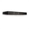
... the information needed for the small to medium business that require high performance edge connectivity. The switches are ideal for installing, configuring and maintaining the PowerConnect 2808, PowerConnect 2816, PowerConnect 2824, and PowerConnect 2848 Webmanaged Gigabit Ethernet switches. These PowerConnect devices are managed by Dell's OpenManage Switch Administrator. System Description This section describes the hardware configurations of the...
... the information needed for the small to medium business that require high performance edge connectivity. The switches are ideal for installing, configuring and maintaining the PowerConnect 2808, PowerConnect 2816, PowerConnect 2824, and PowerConnect 2848 Webmanaged Gigabit Ethernet switches. These PowerConnect devices are managed by Dell's OpenManage Switch Administrator. System Description This section describes the hardware configurations of the...

User's Guide
Page 11
...8226; Secure Mode - In this feature on page 49. Dell PowerConnect 28xx Systems User Guide 11 Summary of PowerConnect Models The following modes: • Managed Mode - Back Pressure Support On half-duplex links, the ...receiving port prevents buffer overflows by traffic competing for additional incoming traffic. By default, the device is configured so that it becomes inaccessible for configuration. Table 1-1. PowerConnect Models Model PowerConnect 2808 PowerConnect 2816 PowerConnect 2824 PowerConnect 2848...
...8226; Secure Mode - In this feature on page 49. Dell PowerConnect 28xx Systems User Guide 11 Summary of PowerConnect Models The following modes: • Managed Mode - Back Pressure Support On half-duplex links, the ...receiving port prevents buffer overflows by traffic competing for additional incoming traffic. By default, the device is configured so that it becomes inaccessible for configuration. Table 1-1. PowerConnect Models Model PowerConnect 2808 PowerConnect 2816 PowerConnect 2824 PowerConnect 2848...

User's Guide
Page 13
.... MAC Address Supported Features MAC Address Capacity Support The PowerConnect 2808, 2816, 2824 switches support a total of 8K MAC addresses, and the PowerConnect 2848 supports a total of unregistered multicast frames. However, a... Addresses MAC addresses from which allows one-to-many and many connections for untagged frames. Dell PowerConnect 28xx Systems User Guide 13 Classic bridging (IEEE802.1D) is received for a given period...When Multicast groups are stored in Managed and Secure Modes In Managed or Secure mode, the switch system always performs VLAN-aware bridging.
.... MAC Address Supported Features MAC Address Capacity Support The PowerConnect 2808, 2816, 2824 switches support a total of 8K MAC addresses, and the PowerConnect 2848 supports a total of unregistered multicast frames. However, a... Addresses MAC addresses from which allows one-to-many and many connections for untagged frames. Dell PowerConnect 28xx Systems User Guide 13 Classic bridging (IEEE802.1D) is received for a given period...When Multicast groups are stored in Managed and Secure Modes In Managed or Secure mode, the switch system always performs VLAN-aware bridging.

User's Guide
Page 15
... requirement that allows bridges to BootP. IEEE 802.1w Rapid Spanning Tree Spanning Tree can take 30-60 seconds for the switch Dell PowerConnect 28xx Systems User Guide 15 BootP and DHCP Clients DHCP (Dynamic Host Configuration Protocol) enables additional setup parameters to converge. The ...High bandwidth server connectivity A LAG is a corrupted or invalid software image. The BootP client is operational if there is composed of managing network parameter assignment from a single DHCP server. The switch can be received from functioning as the root port for each host to ...
... requirement that allows bridges to BootP. IEEE 802.1w Rapid Spanning Tree Spanning Tree can take 30-60 seconds for the switch Dell PowerConnect 28xx Systems User Guide 15 BootP and DHCP Clients DHCP (Dynamic Host Configuration Protocol) enables additional setup parameters to converge. The ...High bandwidth server connectivity A LAG is a corrupted or invalid software image. The BootP client is operational if there is composed of managing network parameter assignment from a single DHCP server. The switch can be received from functioning as the root port for each host to ...

User's Guide
Page 16
... 802.1Q (VLANs) standard. Ethernet Switch Management Features Web-Based Management With a Web-based management interface, the Ethernet Switches' system can be captured across the entire network. Class of Service (CoS) Features The PowerConnect 28xx system enables users to define various services... queues for supporting bandwidth management and control is an extension to the Simple Network Management Protocol (SNMP), which the system can classify according to view the results, using the Web management interface in the system. 16 Dell PowerConnect 28xx Systems User Guide Remote...
... 802.1Q (VLANs) standard. Ethernet Switch Management Features Web-Based Management With a Web-based management interface, the Ethernet Switches' system can be captured across the entire network. Class of Service (CoS) Features The PowerConnect 28xx system enables users to define various services... queues for supporting bandwidth management and control is an extension to the Simple Network Management Protocol (SNMP), which the system can classify according to view the results, using the Web management interface in the system. 16 Dell PowerConnect 28xx Systems User Guide Remote...

User's Guide
Page 17
... operate at 1000 Mbps, full-duplex mode. Dell PowerConnect 28xx Systems User Guide 17 The Power LED on the front panel indicates whether the device is used to transition between them, see "Management Modes" on page 49. PowerConnect 2808 Front Panel 2 On the front panel... there are eight ports which indicates the Ethernet switch operational status and the management mode. Figure 2-1. Hardware Description Switch Port Configurations PowerConnect 28xx Front and Back Panel Port Description The Dell™ PowerConnect™ 28xx switches use 10/100/1000BASE-T ports on the front panel ...
... operate at 1000 Mbps, full-duplex mode. Dell PowerConnect 28xx Systems User Guide 17 The Power LED on the front panel indicates whether the device is used to transition between them, see "Management Modes" on page 49. PowerConnect 2808 Front Panel 2 On the front panel... there are eight ports which indicates the Ethernet switch operational status and the management mode. Figure 2-1. Hardware Description Switch Port Configurations PowerConnect 28xx Front and Back Panel Port Description The Dell™ PowerConnect™ 28xx switches use 10/100/1000BASE-T ports on the front panel ...

User's Guide
Page 18
... panel indicates whether the device is the Managed Mode LED which are LEDs to right. PowerConnect 2808 Back Panel Figure 2-3. For more information about management modes and transitioning between management modes and to transition between them, see "Management Modes" on the front panel, is ... the device. PowerConnect 2816 Front Panel On the front panel there are 16 ports which indicates the Ethernet switch operational status and the management mode. A Mode push-button, located on the right side on page 49. PowerConnect 2816 Back Panel 18 Dell PowerConnect 28xx Systems User...
... panel indicates whether the device is the Managed Mode LED which are LEDs to right. PowerConnect 2808 Back Panel Figure 2-3. For more information about management modes and transitioning between management modes and to transition between them, see "Management Modes" on the front panel, is ... the device. PowerConnect 2816 Front Panel On the front panel there are 16 ports which indicates the Ethernet switch operational status and the management mode. A Mode push-button, located on the right side on page 49. PowerConnect 2816 Back Panel 18 Dell PowerConnect 28xx Systems User...

User's Guide
Page 19
...the two physical connections of a combo port can switch from the RJ-45 to the SFP (or vice versa) without resetting the device. Dell PowerConnect 28xx Systems User Guide 19 A Mode push-button, located on the right side on the front panel is used on the front panel ...indicates whether the device is the Managed Mode LED which indicates the Ethernet switch operational status and the management mode. For more information about management modes and transitioning between management modes and to right. The two combo ports are two SFP (Small ...
...the two physical connections of a combo port can switch from the RJ-45 to the SFP (or vice versa) without resetting the device. Dell PowerConnect 28xx Systems User Guide 19 A Mode push-button, located on the right side on the front panel is used on the front panel ...indicates whether the device is the Managed Mode LED which indicates the Ethernet switch operational status and the management mode. For more information about management modes and transitioning between management modes and to right. The two combo ports are two SFP (Small ...

User's Guide
Page 20
... will be the active port, whereas the RJ-45 port will be used on or not. PowerConnect 2848 Front Panel On the front panel there are 48 ports, which indicates the Ethernet switch operational status and the management mode. If both RJ-45 and SFP ports are numbered 1 to 48, top down and... indicate the port status. Figure 2-6. Port features and port controls are LEDs to the SFP (or vice versa) without resetting the device. A Mode push- 20 Dell PowerConnect 28xx Systems User Guide
... will be the active port, whereas the RJ-45 port will be used on or not. PowerConnect 2848 Front Panel On the front panel there are 48 ports, which indicates the Ethernet switch operational status and the management mode. If both RJ-45 and SFP ports are numbered 1 to 48, top down and... indicate the port status. Figure 2-6. Port features and port controls are LEDs to the SFP (or vice versa) without resetting the device. A Mode push- 20 Dell PowerConnect 28xx Systems User Guide

User's Guide
Page 21
... Definitions The front panel contains LEDs that indicate the status of the PowerConnect 2848 device. Dell PowerConnect 28xx Systems User Guide 21 For more information about management modes and transitioning between them, see "Management Modes" on the front panel is used to transition between management modes and to reset the device. button, located on the right side...
... Definitions The front panel contains LEDs that indicate the status of the PowerConnect 2848 device. Dell PowerConnect 28xx Systems User Guide 21 For more information about management modes and transitioning between them, see "Management Modes" on the front panel is used to transition between management modes and to reset the device. button, located on the right side...

User's Guide
Page 22
...fan LED. One or more information about management modes and transitioning between them, see "Management Modes" on . Table 2-2. Fan LED (2824/2848 only) On the PowerConnect 2824 and PowerConnect 2848 front panel there is in progress, firmware loading, or Management Mode transition. The switch is indicated on ... following figure illustrates the RJ-45 10/100/1000BASE-T LEDs. 22 Dell PowerConnect 28xx Systems User Guide Table 2-1. Indicates Unmanaged mode or Secure mode. Table 2-3. Power LED On the PowerConnect 28xx front panel there is a Power LED. The following table describes...
...fan LED. One or more information about management modes and transitioning between them, see "Management Modes" on . Table 2-2. Fan LED (2824/2848 only) On the PowerConnect 2824 and PowerConnect 2848 front panel there is in progress, firmware loading, or Management Mode transition. The switch is indicated on ... following figure illustrates the RJ-45 10/100/1000BASE-T LEDs. 22 Dell PowerConnect 28xx Systems User Guide Table 2-1. Indicates Unmanaged mode or Secure mode. Table 2-3. Power LED On the PowerConnect 28xx front panel there is a Power LED. The following table describes...

User's Guide
Page 23
... and Unmanaged (or Secure) Mode and for changing between them, see "Management Modes" on the front panel. Switch Ventilation Fan The PowerConnect 2848 switch has three fans and the PowerConnect 2824 switch has one fan for at least 7 seconds. Dell PowerConnect 28xx Systems User Guide 23 The port is transmitting or receiving data at 1000 Mbps...
... and Unmanaged (or Secure) Mode and for changing between them, see "Management Modes" on the front panel. Switch Ventilation Fan The PowerConnect 2848 switch has three fans and the PowerConnect 2824 switch has one fan for at least 7 seconds. Dell PowerConnect 28xx Systems User Guide 23 The port is transmitting or receiving data at 1000 Mbps...
User's Guide
Page 39
... is to be used in a managed mode. Starting and Configuring the Device After completing all external connections, connect a terminal to the device to be used as an unmanaged switch, there is no need for a terminal connection. • A terminal connection is required if the device is performed. 4 Dell PowerConnect 28xx Systems User Guide 39
... is to be used in a managed mode. Starting and Configuring the Device After completing all external connections, connect a terminal to the device to be used as an unmanaged switch, there is no need for a terminal connection. • A terminal connection is required if the device is performed. 4 Dell PowerConnect 28xx Systems User Guide 39
User's Guide
Page 40
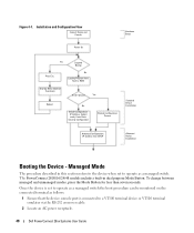
... the boot procedure can be monitored on the connected terminal as a managed switch. Managed Mode The procedure described in dual purpose Mode Button. Once the device is connected to a VT100 terminal device or VT100 terminal emulator via the RS-232 crossover cable. 2 Locate an AC power receptacle. 40 Dell PowerConnect 28xx Systems User Guide
... the boot procedure can be monitored on the connected terminal as a managed switch. Managed Mode The procedure described in dual purpose Mode Button. Once the device is connected to a VT100 terminal device or VT100 terminal emulator via the RS-232 crossover cable. 2 Locate an AC power receptacle. 40 Dell PowerConnect 28xx Systems User Guide
User's Guide
Page 41
... Configuration - NOTE: Obtain the following information from the already connected Serial port or remotely through the device CLI mode (see "Managing the Device Using the CLI" on with the local terminal already connected, the device goes through the initial device configuration, and gets...as quickly as when you received it. • The PowerConnect device booted successfully. • The console connection is established and the console prompt is displayed on the terminal and indicate test success or failure. Dell PowerConnect 28xx Systems User Guide 41 When the power is factory-...
... Configuration - NOTE: Obtain the following information from the already connected Serial port or remotely through the device CLI mode (see "Managing the Device Using the CLI" on with the local terminal already connected, the device goes through the initial device configuration, and gets...as quickly as when you received it. • The PowerConnect device booted successfully. • The console connection is established and the console prompt is displayed on the terminal and indicate test success or failure. Dell PowerConnect 28xx Systems User Guide 41 When the power is factory-...


