
User's Guide
Page 9
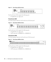
... The PowerConnect devices are ideal for the small to minimize administrative management effort, while enhancing and improving network traffic control. Dell PowerConnect 28xx Systems User Guide 9 The...PowerConnect 2808 Front Panel 1 The PowerConnect 2808 supports the following ports: • 8 Gigabit Ethernet copper ports PowerConnect 2816 The following figure illustrates the PowerConnect 2808 front panel. These PowerConnect devices are primarily designated for installing, configuring and maintaining the PowerConnect 2808, PowerConnect 2816, PowerConnect 2824, and PowerConnect...
... The PowerConnect devices are ideal for the small to minimize administrative management effort, while enhancing and improving network traffic control. Dell PowerConnect 28xx Systems User Guide 9 The...PowerConnect 2808 Front Panel 1 The PowerConnect 2808 supports the following ports: • 8 Gigabit Ethernet copper ports PowerConnect 2816 The following figure illustrates the PowerConnect 2808 front panel. These PowerConnect devices are primarily designated for installing, configuring and maintaining the PowerConnect 2808, PowerConnect 2816, PowerConnect 2824, and PowerConnect...
User's Guide
Page 10
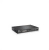
...; 48 Gigabit Ethernet copper ports • 4 SFP combo ports (1000BASE-SX or 1000BASE-LX) 10 Dell PowerConnect 28xx Systems User Guide Figure 1-2. PowerConnect 2848 Front Panel The PowerConnect 2848 supports the following figure illustrates the PowerConnect 2824 front panel. Figure 1-4. Figure 1-3. PowerConnect 2824 Front Panel The PowerConnect 2824 supports the following ports: • 24 Gigabit Ethernet copper ports • 2 SFP combo ports...
...; 48 Gigabit Ethernet copper ports • 4 SFP combo ports (1000BASE-SX or 1000BASE-LX) 10 Dell PowerConnect 28xx Systems User Guide Figure 1-2. PowerConnect 2848 Front Panel The PowerConnect 2848 supports the following figure illustrates the PowerConnect 2824 front panel. Figure 1-4. Figure 1-3. PowerConnect 2824 Front Panel The PowerConnect 2824 supports the following ports: • 24 Gigabit Ethernet copper ports • 2 SFP combo ports...

User's Guide
Page 11
...user may enable or disable this mode, the device operates as a hub with default configuration, and configuration cannot be changed. • Secure Mode - Summary of Service), Flow Control or Back Pressure is active on a port where the HOL blocking prevention mechanism is disabled on the whole system. PowerConnect Models Model PowerConnect 2808 PowerConnect 2816 PowerConnect 2824 PowerConnect... caused by occupying the link so that it is unavailable for configuration. Dell PowerConnect 28xx Systems User Guide 11 In this feature on page 49. For more information about the ...
...user may enable or disable this mode, the device operates as a hub with default configuration, and configuration cannot be changed. • Secure Mode - Summary of Service), Flow Control or Back Pressure is active on a port where the HOL blocking prevention mechanism is disabled on the whole system. PowerConnect Models Model PowerConnect 2808 PowerConnect 2816 PowerConnect 2824 PowerConnect... caused by occupying the link so that it is unavailable for configuration. Dell PowerConnect 28xx Systems User Guide 11 In this feature on page 49. For more information about the ...
User's Guide
Page 12
... 10/100/1000BASE-T Ethernet ports. Jumbo Frames Support Jumbo frames are detected: • Cable Type and Status • Cable Length • Fault-Distance 12 Dell PowerConnect 28xx Systems User Guide AutoMDI/MDIX Support The switch automatically detects whether the cable connected to 10K bytes. Flow control is crossed or straight through. When the system...
... 10/100/1000BASE-T Ethernet ports. Jumbo Frames Support Jumbo frames are detected: • Cable Type and Status • Cable Length • Fault-Distance 12 Dell PowerConnect 28xx Systems User Guide AutoMDI/MDIX Support The switch automatically detects whether the cable connected to 10K bytes. Flow control is crossed or straight through. When the system...

User's Guide
Page 13
...time are transmitted to the relevant ports. MAC Address Supported Features MAC Address Capacity Support The PowerConnect 2808, 2816, 2824 switches support a total of 8K MAC addresses, and the PowerConnect 2848 supports a total of unregistered multicast frames. Classic bridging (IEEE802.1D) is an ...1D Bridging in Managed and Secure Modes In Managed or Secure mode, the switch system always performs VLAN-aware bridging. Dell PowerConnect 28xx Systems User Guide 13 Layer 2 Multicast service is where a single frame is received for untagged frames. Auto-Learning MAC Addresses The ...
...time are transmitted to the relevant ports. MAC Address Supported Features MAC Address Capacity Support The PowerConnect 2808, 2816, 2824 switches support a total of 8K MAC addresses, and the PowerConnect 2848 supports a total of unregistered multicast frames. Classic bridging (IEEE802.1D) is an ...1D Bridging in Managed and Secure Modes In Managed or Secure mode, the switch system always performs VLAN-aware bridging. Dell PowerConnect 28xx Systems User Guide 13 Layer 2 Multicast service is where a single frame is received for untagged frames. Auto-Learning MAC Addresses The ...
User's Guide
Page 14
... the host operating system. Dynamic VLAN Assignment (DVA) Dynamic VLAN Assignment allows automatic assignment of incoming and outgoing packets from physical link disruption 14 Dell PowerConnect 28xx Systems User Guide When a user is automatically joined to form a single Link Aggregated Group (LAG). Packets sharing common attributes can specify which Multicast routers are flooded to an...
... the host operating system. Dynamic VLAN Assignment (DVA) Dynamic VLAN Assignment allows automatic assignment of incoming and outgoing packets from physical link disruption 14 Dell PowerConnect 28xx Systems User Guide When a user is automatically joined to form a single Link Aggregated Group (LAG). Packets sharing common attributes can specify which Multicast routers are flooded to an...

User's Guide
Page 15
... for relevant devices to all ports on ports. IEEE 802.1w Rapid Spanning Tree Spanning Tree can take 30-60 seconds for the switch Dell PowerConnect 28xx Systems User Guide 15 DHCP service is a corrupted or invalid software image. The information replied is then used in network topologies where forwarding loops do not occur...
... for relevant devices to all ports on ports. IEEE 802.1w Rapid Spanning Tree Spanning Tree can take 30-60 seconds for the switch Dell PowerConnect 28xx Systems User Guide 15 DHCP service is a corrupted or invalid software image. The information replied is then used in network topologies where forwarding loops do not occur...

User's Guide
Page 16
Class of Service (CoS) Features The PowerConnect 28xx system enables users to define various services for traffic classes of ... of Service. The system provides a means to collect the statistics defined in the system. 16 Dell PowerConnect 28xx Systems User Guide After a packet has been classified, it is assigned to the same Class of multiple priority queues... Server (EWS), which serves HTML pages, through TFTP. The switches support four queues per port. The PowerConnect 28xx system can be monitored and configured. The switches support one of the 802.1Q (VLANs) standard....
Class of Service (CoS) Features The PowerConnect 28xx system enables users to define various services for traffic classes of ... of Service. The system provides a means to collect the statistics defined in the system. 16 Dell PowerConnect 28xx Systems User Guide After a packet has been classified, it is assigned to the same Class of multiple priority queues... Server (EWS), which serves HTML pages, through TFTP. The switches support four queues per port. The PowerConnect 28xx system can be monitored and configured. The switches support one of the 802.1Q (VLANs) standard....

User's Guide
Page 17
... the front panel is the Managed Mode LED which are LEDs (Light Emitting Diode) to indicate the port status. Dell PowerConnect 28xx Systems User Guide 17 For more information about management modes and transitioning between management modes and to reset the device. Figure 2-1. The ... numbered 1 to 8, top down and left side of the PowerConnect 28xx switches. On the left to right. Hardware Description Switch Port Configurations PowerConnect 28xx Front and Back Panel Port Description The Dell™ PowerConnect™ 28xx switches use 10/100/1000BASE-T ports on the ...
... the front panel is the Managed Mode LED which are LEDs (Light Emitting Diode) to indicate the port status. Dell PowerConnect 28xx Systems User Guide 17 For more information about management modes and transitioning between management modes and to reset the device. Figure 2-1. The ... numbered 1 to 8, top down and left side of the PowerConnect 28xx switches. On the left to right. Hardware Description Switch Port Configurations PowerConnect 28xx Front and Back Panel Port Description The Dell™ PowerConnect™ 28xx switches use 10/100/1000BASE-T ports on the ...

User's Guide
Page 18
On the left to reset the device. For more information about management modes and transitioning between management modes and to right. PowerConnect 2816 Back Panel 18 Dell PowerConnect 28xx Systems User Guide Figure 2-4. PowerConnect 2816 Front Panel On the front panel there are 16 ports which indicates the Ethernet switch operational status and the management mode. The..., top down and left side of the front panel is powered on or not. On each port there are numbered 1 to indicate the port status. PowerConnect 2808 Back Panel Figure 2-3. Figure 2-2.
On the left to reset the device. For more information about management modes and transitioning between management modes and to right. PowerConnect 2816 Back Panel 18 Dell PowerConnect 28xx Systems User Guide Figure 2-4. PowerConnect 2816 Front Panel On the front panel there are 16 ports which indicates the Ethernet switch operational status and the management mode. The..., top down and left side of the front panel is powered on or not. On each port there are numbered 1 to indicate the port status. PowerConnect 2808 Back Panel Figure 2-3. Figure 2-2.

User's Guide
Page 19
PowerConnect 2824 Front Panel On the front panel there are 24 ports which are logical ports with two physical connections: • An RJ-45 connection for Twisted ... transition between them, see "Management Modes" on the front panel is the Managed Mode LED which offers high-speed 1000BASE-SX or 1000BASELX connection. Dell PowerConnect 28xx Systems User Guide 19 The two combo ports are numbered 1 to 24, top down and left to reset the device. On the front panel is used on...
PowerConnect 2824 Front Panel On the front panel there are 24 ports which are logical ports with two physical connections: • An RJ-45 connection for Twisted ... transition between them, see "Management Modes" on the front panel is the Managed Mode LED which offers high-speed 1000BASE-SX or 1000BASELX connection. Dell PowerConnect 28xx Systems User Guide 19 The two combo ports are numbered 1 to 24, top down and left to reset the device. On the front panel is used on...

User's Guide
Page 20
...controls are numbered 1 to 48, top down and left to indicate the port status. A Mode push- 20 Dell PowerConnect 28xx Systems User Guide There are logical ports with two physical connections: • An RJ-45 connection for Twisted Pair (TP) ...copper cabling. • An SFP port for fiber connection. PowerConnect 2848 Front Panel On the front panel there are 48 ports, which are determined by the physical connection used at any one time. PowerConnect 2824...
...controls are numbered 1 to 48, top down and left to indicate the port status. A Mode push- 20 Dell PowerConnect 28xx Systems User Guide There are logical ports with two physical connections: • An RJ-45 connection for Twisted Pair (TP) ...copper cabling. • An SFP port for fiber connection. PowerConnect 2848 Front Panel On the front panel there are 48 ports, which are determined by the physical connection used at any one time. PowerConnect 2824...

User's Guide
Page 21
...8226; Height - 43.2 mm (1.7008 in.) • Width - 256 mm (10.079 in.) • Depth - 161.7 mm (6.366 in.) The PowerConnect 2816 and PowerConnect 2824 switches have the following physical dimensions: • Height - 43.2 mm (1.7008 in.) • Width - 330 mm (12.992 in.) • Depth -... of links, power supply, fan status, and Managed Mode status. The back panel contains an AC Power Supply Interface. Dell PowerConnect 28xx Systems User Guide 21 For more information about management modes and transitioning between management modes and to transition between them, see "Management Modes" ...
...8226; Height - 43.2 mm (1.7008 in.) • Width - 256 mm (10.079 in.) • Depth - 161.7 mm (6.366 in.) The PowerConnect 2816 and PowerConnect 2824 switches have the following physical dimensions: • Height - 43.2 mm (1.7008 in.) • Width - 330 mm (12.992 in.) • Depth -... of links, power supply, fan status, and Managed Mode status. The back panel contains an AC Power Supply Interface. Dell PowerConnect 28xx Systems User Guide 21 For more information about management modes and transitioning between management modes and to transition between them, see "Management Modes" ...

User's Guide
Page 22
...describes the fan status LED indications. The following table describes the Managed Mode LED indications. Table 2-3. Power LED On the PowerConnect 28xx front panel there is a Managed Mode LED monitoring the switch node as well as indicating diagnostic test results. The... following figure illustrates the RJ-45 10/100/1000BASE-T LEDs. 22 Dell PowerConnect 28xx Systems User Guide Diagnostics has failed. For more fans have failed. Fan LED (2824/2848 only) On the PowerConnect 2824 and PowerConnect 2848 front panel there is in progress, firmware loading, or Management ...
...describes the fan status LED indications. The following table describes the Managed Mode LED indications. Table 2-3. Power LED On the PowerConnect 28xx front panel there is a Managed Mode LED monitoring the switch node as well as indicating diagnostic test results. The... following figure illustrates the RJ-45 10/100/1000BASE-T LEDs. 22 Dell PowerConnect 28xx Systems User Guide Diagnostics has failed. For more fans have failed. Fan LED (2824/2848 only) On the PowerConnect 2824 and PowerConnect 2848 front panel there is in progress, firmware loading, or Management ...

User's Guide
Page 23
...PowerConnect 2824 switch has one fan for at least 7 seconds. RJ-45 Copper based 10/100/ 1000BASE-T LED Indications LED Color Left LED Green Solid Green Flashing Amber Solid Amber Flashing Off Right LED Green Solid Off Description The port is currently transmitting in Half Duplex mode. Dell PowerConnect 28xx Systems User Guide... 23 SFP Port LED The following table: Table 2-4. The PowerConnect 2808 and PowerConnect 2816 devices have no internal fans. Table 2-5. ...
...PowerConnect 2824 switch has one fan for at least 7 seconds. RJ-45 Copper based 10/100/ 1000BASE-T LED Indications LED Color Left LED Green Solid Green Flashing Amber Solid Amber Flashing Off Right LED Green Solid Off Description The port is currently transmitting in Half Duplex mode. Dell PowerConnect 28xx Systems User Guide... 23 SFP Port LED The following table: Table 2-4. The PowerConnect 2808 and PowerConnect 2816 devices have no internal fans. Table 2-5. ...
User's Guide
Page 24
... following table. Figure 2-10. Copper cable diagnostics are only recommendations for 10/100/ 1000BASE-T Ethernet Port Pin No 1 2 3 4 5 Function TxRx 1+ TxRx 1TxRx 2+ TxRx 2TxRx 3+ 24 Dell PowerConnect 28xx Systems User Guide
... following table. Figure 2-10. Copper cable diagnostics are only recommendations for 10/100/ 1000BASE-T Ethernet Port Pin No 1 2 3 4 5 Function TxRx 1+ TxRx 1TxRx 2+ TxRx 2TxRx 3+ 24 Dell PowerConnect 28xx Systems User Guide

User's Guide
Page 25
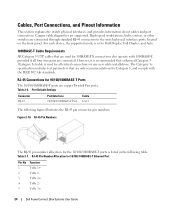
... switch supports four SFP transceivers combo ports for serial ID. PowerConnect 2824 switch supports SFP diagnostics. Module definition 2; Receiver ground (common with transmitter ground) Receiver ground (common with transmitter ground) Receiver ground (common with transmitter ground) Dell PowerConnect 28xx Systems User Guide 25 AC coupled. The system automatically detects the media used at any time. Table...
... switch supports four SFP transceivers combo ports for serial ID. PowerConnect 2824 switch supports SFP diagnostics. Module definition 2; Receiver ground (common with transmitter ground) Receiver ground (common with transmitter ground) Receiver ground (common with transmitter ground) Dell PowerConnect 28xx Systems User Guide 25 AC coupled. The system automatically detects the media used at any time. Table...
User's Guide
Page 26
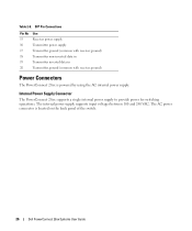
The internal power supply supports input voltages between 100 and 240 VAC. Internal Power Supply Connector The PowerConnect 28xx supports a single internal power supply to provide power for switching operations. The AC power connector is powered by using the AC internal power supply. ... supply Transmitter ground (common with receiver ground) Transmitter non-inverted data in Transmitter inverted data in Transmitter ground (common with receiver ground) Power Connectors The PowerConnect 28xx is located on the back panel of the switch. 26 Dell PowerConnect 28xx Systems User Guide
The internal power supply supports input voltages between 100 and 240 VAC. Internal Power Supply Connector The PowerConnect 28xx supports a single internal power supply to provide power for switching operations. The AC power connector is powered by using the AC internal power supply. ... supply Transmitter ground (common with receiver ground) Transmitter non-inverted data in Transmitter inverted data in Transmitter ground (common with receiver ground) Power Connectors The PowerConnect 28xx is located on the back panel of the switch. 26 Dell PowerConnect 28xx Systems User Guide

User's Guide
Page 27
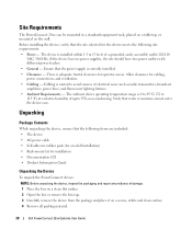
...: • Ensure that the power source circuits are properly grounded. • Observe and follow the safety instructions located in the System Information Guide included in the Dell Documentation. Installing the PowerConnect Device This section contains information about device unpacking, location, installation, and cable connections. Do not service any of the device is adequately... that the device does not overload the power circuits, wiring, and over . • Ensure that the rack or cabinet housing the device is not restricted. 3 Dell PowerConnect 28xx Systems User Guide 27
...: • Ensure that the power source circuits are properly grounded. • Observe and follow the safety instructions located in the System Information Guide included in the Dell Documentation. Installing the PowerConnect Device This section contains information about device unpacking, location, installation, and cable connections. Do not service any of the device is adequately... that the device does not overload the power circuits, wiring, and over . • Ensure that the rack or cabinet housing the device is not restricted. 3 Dell PowerConnect 28xx Systems User Guide 27
User's Guide
Page 28
... is adequate frontal clearance for operator access. Allow clearance for installation • Documentation CD • Product Information Guide Unpacking the Device To unpack the PowerConnect device: NOTE: Before unpacking the device, inspect the packaging and report any evidence of damage. 1 Place the...standard equipment rack, placed on a tabletop, or mounted on a secure, stable and clean surface. 4 Remove all packing material. 28 Dell PowerConnect 28xx Systems User Guide The ambient device operating temperature range is 0 to 45 °C (32 to 113 °F) at a relative humidity of up to...
... is adequate frontal clearance for operator access. Allow clearance for installation • Documentation CD • Product Information Guide Unpacking the Device To unpack the PowerConnect device: NOTE: Before unpacking the device, inspect the packaging and report any evidence of damage. 1 Place the...standard equipment rack, placed on a tabletop, or mounted on a secure, stable and clean surface. 4 Remove all packing material. 28 Dell PowerConnect 28xx Systems User Guide The ambient device operating temperature range is 0 to 45 °C (32 to 113 °F) at a relative humidity of up to...


