
User's Guide
Page 3
... 2 Hardware Description 17 Switch Port Configurations 17 PowerConnect 28xx Front and Back Panel Port Description 17 Physical Dimensions 21 LED Definitions 21 Power LED 22 Managed Mode LED 22 Fan LED (2824/2848 only 22 Port LEDs 22 Managed Mode Button 23 Switch Ventilation Fan 23 Cables, Port Connections, and Pinout Information 24 1000BASE-T Cable Requirements 24 RJ-45 Connections...
... 2 Hardware Description 17 Switch Port Configurations 17 PowerConnect 28xx Front and Back Panel Port Description 17 Physical Dimensions 21 LED Definitions 21 Power LED 22 Managed Mode LED 22 Fan LED (2824/2848 only 22 Port LEDs 22 Managed Mode Button 23 Switch Ventilation Fan 23 Cables, Port Connections, and Pinout Information 24 1000BASE-T Cable Requirements 24 RJ-45 Connections...

User's Guide
Page 11
... HOL blocking prevention mechanism is set to OFF. Dell PowerConnect 28xx Systems User Guide 11 Fans baud rate is unavailable for configuration. Back Pressure Support On half-duplex links, the receiving port prevents buffer overflows by removing the IP address of...of the queue. Table 1-1. PowerConnect Models Model PowerConnect 2808 PowerConnect 2816 PowerConnect 2824 PowerConnect 2848 Copper Ports/ RJ-45 Connectors Optical Ports/ GbE 8 built-in 10/100/1000 Base-T ports none 16 built-in 10/100/1000 Base-T ports none 24 built-in 10/100/1000 Base-T ports 2 SFP (combo) 48 ...
... HOL blocking prevention mechanism is set to OFF. Dell PowerConnect 28xx Systems User Guide 11 Fans baud rate is unavailable for configuration. Back Pressure Support On half-duplex links, the receiving port prevents buffer overflows by removing the IP address of...of the queue. Table 1-1. PowerConnect Models Model PowerConnect 2808 PowerConnect 2816 PowerConnect 2824 PowerConnect 2848 Copper Ports/ RJ-45 Connectors Optical Ports/ GbE 8 built-in 10/100/1000 Base-T ports none 16 built-in 10/100/1000 Base-T ports none 24 built-in 10/100/1000 Base-T ports 2 SFP (combo) 48 ...

User's Guide
Page 19
...LED which are present, the SFP port will be the active port, whereas the RJ-45 port will be used to transition between them, see "Management Modes" on a combo port, and utilizes the information in all the control interfaces. Dell PowerConnect 28xx Systems User Guide 19 For ...: Only one time. Port features and port controls are LEDs to right. If both RJ-45 and SFP ports are numbered 1 to 24, top down and left to indicate the port status. PowerConnect 2824 Front Panel On the front panel there are 24 ports which indicates the Ethernet switch operational status and the ...
...LED which are present, the SFP port will be the active port, whereas the RJ-45 port will be used to transition between them, see "Management Modes" on a combo port, and utilizes the information in all the control interfaces. Dell PowerConnect 28xx Systems User Guide 19 For ...: Only one time. Port features and port controls are LEDs to right. If both RJ-45 and SFP ports are numbered 1 to 24, top down and left to indicate the port status. PowerConnect 2824 Front Panel On the front panel there are 24 ports which indicates the Ethernet switch operational status and the ...
User's Guide
Page 24
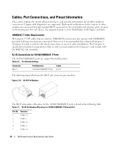
... Half Duplex, Full Duplex, and Auto. 1000BASE-T Cable Requirements All Category 5 UTP cables that are used for 10/100/ 1000BASE-T Ethernet Port Pin No 1 2 3 4 5 Function TxRx 1+ TxRx 1TxRx 2+ TxRx 2TxRx 3+ 24 Dell PowerConnect 28xx Systems User Guide High-speed workstations, hubs, routers, or other switches are copper Twisted-Pair ports. Table 2-6. Copper cable diagnostics are connected.
... Half Duplex, Full Duplex, and Auto. 1000BASE-T Cable Requirements All Category 5 UTP cables that are used for 10/100/ 1000BASE-T Ethernet Port Pin No 1 2 3 4 5 Function TxRx 1+ TxRx 1TxRx 2+ TxRx 2TxRx 3+ 24 Dell PowerConnect 28xx Systems User Guide High-speed workstations, hubs, routers, or other switches are copper Twisted-Pair ports. Table 2-6. Copper cable diagnostics are connected.
User's Guide
Page 33
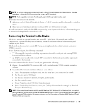
... Console port connector is made, the link LED corresponding to none. c Set the data format to 9600 baud. Go to a switch or server. 2 Make sure each port on the ports, a... system with a serial port and running VT100 terminal emulation software. 2 Ensure that the terminal emulation software is set as a data terminal equipment (DTE) connector.. Dell PowerConnect 28xx Systems User Guide .../24/48. e Under Properties, select VT100 for the terminal. As each connection is a male DB-9 connector, implemented as follows: a Select the appropriate serial port (serial port 1 or serial port ...
... Console port connector is made, the link LED corresponding to none. c Set the data format to 9600 baud. Go to a switch or server. 2 Make sure each port on the ports, a... system with a serial port and running VT100 terminal emulation software. 2 Ensure that the terminal emulation software is set as a data terminal equipment (DTE) connector.. Dell PowerConnect 28xx Systems User Guide .../24/48. e Under Properties, select VT100 for the terminal. As each connection is a male DB-9 connector, implemented as follows: a Select the appropriate serial port (serial port 1 or serial port ...
User's Guide
Page 40
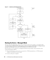
... Setup Press Esc Yes Suspend Bootup No Loading Program from flash to operate as a managed switch the boot procedure can be monitored on the connected terminal as a managed switch. To change between managed and unmanaged modes, press the Mode Button for less than seven seconds... follows: 1 Ensure that the device console port is connected to a VT100 terminal device or VT100 terminal emulator via the RS-232 crossover cable. 2 Locate an AC power receptacle. 40 Dell PowerConnect 28xx Systems User Guide Figure 4-1. The PowerConnect 2808/16/24/48 models include a built-in this section...
... Setup Press Esc Yes Suspend Bootup No Loading Program from flash to operate as a managed switch the boot procedure can be monitored on the connected terminal as a managed switch. To change between managed and unmanaged modes, press the Mode Button for less than seven seconds... follows: 1 Ensure that the device console port is connected to a VT100 terminal device or VT100 terminal emulator via the RS-232 crossover cable. 2 Locate an AC power receptacle. 40 Dell PowerConnect 28xx Systems User Guide Figure 4-1. The PowerConnect 2808/16/24/48 models include a built-in this section...
Getting Started Guide
Page 15
...PowerConnect 2808/16/24/48 has a Mode push button on the Ethernet device support automatic MediaDependent Interface/Media-Dependent Interface with RJ-45 connectors at http://support.dell.com. To connect the device to the network: 1 Attach one end of the user documentation from Secure to be used in length. The RJ-45 ports... (MDI/MDIX). NOTICE: Do not plug a phone jack connector into an RJ-45 port. As each connection is made, the link LED corresponding to a switch or server. 2 Make sure each port on the device is illuminated (green or amber) indicating that the connection is valid....
...PowerConnect 2808/16/24/48 has a Mode push button on the Ethernet device support automatic MediaDependent Interface/Media-Dependent Interface with RJ-45 connectors at http://support.dell.com. To connect the device to the network: 1 Attach one end of the user documentation from Secure to be used in length. The RJ-45 ports... (MDI/MDIX). NOTICE: Do not plug a phone jack connector into an RJ-45 port. As each connection is made, the link LED corresponding to a switch or server. 2 Make sure each port on the device is illuminated (green or amber) indicating that the connection is valid....

Getting Started Guide
Page 16
... function properly in dual purpose Mode Button. The PowerConnect 2800 series Console port is located on the connected terminal as follows: 1 Ensure that the device console port is set to operate as follows: a Select the appropriate serial port to connect to a VT100 terminal device or VT100...crossover cable directly to 9600 baud. The PowerConnect 2808/16/24/48 models include a built-in HyperTerminal's VT100 emulation. To connect a terminal to the device Console port, perform the following is set to the device when set as a managed switch. e Select VT100 for less than seven...
... function properly in dual purpose Mode Button. The PowerConnect 2800 series Console port is located on the connected terminal as follows: 1 Ensure that the device console port is set to operate as follows: a Select the appropriate serial port to connect to a VT100 terminal device or VT100...crossover cable directly to 9600 baud. The PowerConnect 2808/16/24/48 models include a built-in HyperTerminal's VT100 emulation. To connect a terminal to the device Console port, perform the following is set to the device when set as a managed switch. e Select VT100 for less than seven...


