
User's Guide
Page 3
... of Service (CoS) Features 16 Ethernet Switch Management Features 16 2 Hardware Description 17 Switch Port Configurations 17 PowerConnect 28xx Front and Back Panel Port Description 17 Physical Dimensions 21 LED Definitions 21 Power LED 22 Managed Mode LED 22 Fan LED (2824/2848 only 22 Port LEDs 22 Managed Mode Button 23 Switch Ventilation Fan 23 Cables...
... of Service (CoS) Features 16 Ethernet Switch Management Features 16 2 Hardware Description 17 Switch Port Configurations 17 PowerConnect 28xx Front and Back Panel Port Description 17 Physical Dimensions 21 LED Definitions 21 Power LED 22 Managed Mode LED 22 Fan LED (2824/2848 only 22 Port LEDs 22 Managed Mode Button 23 Switch Ventilation Fan 23 Cables...
User's Guide
Page 4
Power Connectors 26 Internal Power Supply Connector 26 3 Installing the PowerConnect Device 27 Installation Precautions 27 Site Requirements 28 Unpacking 28 Package Contents 28 Unpacking the Device 28 Mounting the Device 29 Overview 29 Device Rack ...-Negotiation 36 MDI/MDIX 36 Flow Control 36 Back Pressure 36 Switching Port Default Settings 37 4 Starting and Configuring the Device 39 Booting the Device - Managed Mode 40 Initial Configuration - Managed Mode 41 Advanced Configuration 44 Retrieving an IP Address From a DHCP Server 45 4 Contents
Power Connectors 26 Internal Power Supply Connector 26 3 Installing the PowerConnect Device 27 Installation Precautions 27 Site Requirements 28 Unpacking 28 Package Contents 28 Unpacking the Device 28 Mounting the Device 29 Overview 29 Device Rack ...-Negotiation 36 MDI/MDIX 36 Flow Control 36 Back Pressure 36 Switching Port Default Settings 37 4 Starting and Configuring the Device 39 Booting the Device - Managed Mode 40 Initial Configuration - Managed Mode 41 Advanced Configuration 44 Retrieving an IP Address From a DHCP Server 45 4 Contents
User's Guide
Page 5
... Download 46 Erase FLASH File 46 Erasing the Device Configuration 47 Password Recovery 47 Software Download Through TFTP Server 47 Management Modes 49 Default Values 49 Transitioning Between Modes 50 Returning to Managed Mode 51 5 Using Dell OpenManage Switch Administrator 53 Understanding the Interface 53 Device Representation 54 Using the Switch Administrator Buttons 55 Information Buttons...
... Download 46 Erase FLASH File 46 Erasing the Device Configuration 47 Password Recovery 47 Software Download Through TFTP Server 47 Management Modes 49 Default Values 49 Transitioning Between Modes 50 Returning to Managed Mode 51 5 Using Dell OpenManage Switch Administrator 53 Understanding the Interface 53 Device Representation 54 Using the Switch Administrator Buttons 55 Information Buttons...

User's Guide
Page 11
...In this feature on page 49. For more information about the management modes, see "Management Modes" on a per-port basis. Dell PowerConnect 28xx Systems User Guide 11 The user may enable or disable this mode, the device operates as a hub with default configuration, and ...Mode - HOL blocking queues packets, and the packets at the head of Service), Flow Control or Back Pressure is active on a port where the HOL blocking prevention mechanism is unavailable for the same egress port resources. PowerConnect Models Model PowerConnect 2808 PowerConnect 2816 PowerConnect 2824 PowerConnect...
...In this feature on page 49. For more information about the management modes, see "Management Modes" on a per-port basis. Dell PowerConnect 28xx Systems User Guide 11 The user may enable or disable this mode, the device operates as a hub with default configuration, and ...Mode - HOL blocking queues packets, and the packets at the head of Service), Flow Control or Back Pressure is active on a port where the HOL blocking prevention mechanism is unavailable for the same egress port resources. PowerConnect Models Model PowerConnect 2808 PowerConnect 2816 PowerConnect 2824 PowerConnect...

User's Guide
Page 17
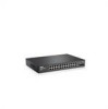
... whether the device is used to right. Dell PowerConnect 28xx Systems User Guide 17 The combo 1000 Mbps optical ports can operate at 1000 Mbps, full-duplex mode. On the left to transition between them, see "Management Modes" on or not. The Gigabit Ethernet ports... on page 49. For more information about management modes and transitioning between management modes and to 8, top down and left side of the PowerConnect 28xx switches. These ports support autonegotiation, duplex mode (Half or Full duplex), and flow control. PowerConnect 2808 Front Panel 2 On the front panel...
... whether the device is used to right. Dell PowerConnect 28xx Systems User Guide 17 The combo 1000 Mbps optical ports can operate at 1000 Mbps, full-duplex mode. On the left to transition between them, see "Management Modes" on or not. The Gigabit Ethernet ports... on page 49. For more information about management modes and transitioning between management modes and to 8, top down and left side of the PowerConnect 28xx switches. These ports support autonegotiation, duplex mode (Half or Full duplex), and flow control. PowerConnect 2808 Front Panel 2 On the front panel...

User's Guide
Page 18
... port status. PowerConnect 2808 Back Panel Figure 2-3. PowerConnect 2816 Back Panel 18 Dell PowerConnect 28xx Systems User Guide Figure 2-2. The Power LED on the front panel indicates whether the device is the Managed Mode LED which are LEDs to transition between them, see "Management Modes" on or not. For more information about management modes and transitioning between management modes and to 16...
... port status. PowerConnect 2808 Back Panel Figure 2-3. PowerConnect 2816 Back Panel 18 Dell PowerConnect 28xx Systems User Guide Figure 2-2. The Power LED on the front panel indicates whether the device is the Managed Mode LED which are LEDs to transition between them, see "Management Modes" on or not. For more information about management modes and transitioning between management modes and to 16...

User's Guide
Page 19
...PowerConnect 2824 Front Panel On the front panel there are 24 ports which are LEDs to reset the device. Port features and port controls are present, the SFP port will be the active port, whereas the RJ-45 port will be used to transition between them, see "Management Modes...) ports, designated as ports 23 and 24, for swappable optical transceiver, which indicates the Ethernet switch operational status and the management mode. Dell PowerConnect 28xx Systems User Guide 19 Figure 2-5. NOTE: The system can be disabled. There are logical ports with two physical connections:...
...PowerConnect 2824 Front Panel On the front panel there are 24 ports which are LEDs to reset the device. Port features and port controls are present, the SFP port will be the active port, whereas the RJ-45 port will be used to transition between them, see "Management Modes...) ports, designated as ports 23 and 24, for swappable optical transceiver, which indicates the Ethernet switch operational status and the management mode. Dell PowerConnect 28xx Systems User Guide 19 Figure 2-5. NOTE: The system can be disabled. There are logical ports with two physical connections:...

User's Guide
Page 20
... side of a combo port can switch from the RJ-45 to the SFP (or vice versa) without resetting the device. A Mode push- 20 Dell PowerConnect 28xx Systems User Guide There are LEDs to right. NOTE: The system can be disabled. The system automatically detects the media used on... Managed Mode LED which are logical ports with two physical connections: • An RJ-45 connection for Twisted Pair (TP) copper cabling. • An SFP port for fiber connection. The four combo ports are numbered 1 to 48, top down and left to indicate the port status. Figure 2-6. PowerConnect 2824...
... side of a combo port can switch from the RJ-45 to the SFP (or vice versa) without resetting the device. A Mode push- 20 Dell PowerConnect 28xx Systems User Guide There are LEDs to right. NOTE: The system can be disabled. The system automatically detects the media used on... Managed Mode LED which are logical ports with two physical connections: • An RJ-45 connection for Twisted Pair (TP) copper cabling. • An SFP port for fiber connection. The four combo ports are numbered 1 to 48, top down and left to indicate the port status. Figure 2-6. PowerConnect 2824...

User's Guide
Page 21
... PowerConnect 2816 and PowerConnect 2824 switches have the following physical dimensions: • Height - 43.2 mm (1.7008 in.) • Width - 330 mm (12.992 in.) • Depth - 230.50 mm (9.075 in .) LED Definitions The front panel contains LEDs that indicate the status of the PowerConnect 2848 device. For more information about management modes and transitioning between management modes...
... PowerConnect 2816 and PowerConnect 2824 switches have the following physical dimensions: • Height - 43.2 mm (1.7008 in.) • Width - 330 mm (12.992 in.) • Depth - 230.50 mm (9.075 in .) LED Definitions The front panel contains LEDs that indicate the status of the PowerConnect 2848 device. For more information about management modes and transitioning between management modes...

User's Guide
Page 22
...2824/2848 only) On the PowerConnect 2824 and PowerConnect 2848 front panel there is a Power LED. Fan LED Indications LED Color Green Solid Red Solid Description All fans are operating correctly. One or more information about management modes and transitioning between them, see "Management Modes... or Management Mode transition. The following figure illustrates the RJ-45 10/100/1000BASE-T LEDs. 22 Dell PowerConnect 28xx Systems User Guide Indicates the switch is turned on . Indicates Unmanaged mode or Secure mode. Managed Mode LED On the PowerConnect 28xx ...
...2824/2848 only) On the PowerConnect 2824 and PowerConnect 2848 front panel there is a Power LED. Fan LED Indications LED Color Green Solid Red Solid Description All fans are operating correctly. One or more information about management modes and transitioning between them, see "Management Modes... or Management Mode transition. The following figure illustrates the RJ-45 10/100/1000BASE-T LEDs. 22 Dell PowerConnect 28xx Systems User Guide Indicates the switch is turned on . Indicates Unmanaged mode or Secure mode. Managed Mode LED On the PowerConnect 28xx ...

User's Guide
Page 23
...Link is linked at 10 or 100 Mbps. The Mode button is for resetting the device. For more information about management modes and transitioning between Managed Mode and Unmanaged (or Secure) Mode and for changing between them, see "Management Modes" on the front panel. RJ-45 Copper-based .... To reset the device, press and hold the button for system ventilation. Dell PowerConnect 28xx Systems User Guide 23 Switch Ventilation Fan The PowerConnect 2848 switch has three fans and the PowerConnect 2824 switch has one fan for at either 10 or 100 Mbps. Green Flashing Activity...
...Link is linked at 10 or 100 Mbps. The Mode button is for resetting the device. For more information about management modes and transitioning between Managed Mode and Unmanaged (or Secure) Mode and for changing between them, see "Management Modes" on the front panel. RJ-45 Copper-based .... To reset the device, press and hold the button for system ventilation. Dell PowerConnect 28xx Systems User Guide 23 Switch Ventilation Fan The PowerConnect 2848 switch has three fans and the PowerConnect 2824 switch has one fan for at either 10 or 100 Mbps. Green Flashing Activity...
User's Guide
Page 39
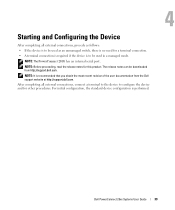
... the Device After completing all external connections, connect a terminal to the device to be downloaded from the Dell support website at http://support.dell.com. NOTE: It is performed. 4 Dell PowerConnect 28xx Systems User Guide 39 The release notes can be used as an unmanaged switch, there is no need... and for this product. After completing all external connections, procede as follows: • If the device is to be used in a managed mode. NOTE: The PowerConnect 2808 has an internal serial port. NOTE: Before proceeding, read the release notes for other procedures.
... the Device After completing all external connections, connect a terminal to the device to be downloaded from the Dell support website at http://support.dell.com. NOTE: It is performed. 4 Dell PowerConnect 28xx Systems User Guide 39 The release notes can be used as an unmanaged switch, there is no need... and for this product. After completing all external connections, procede as follows: • If the device is to be used in a managed mode. NOTE: The PowerConnect 2808 has an internal serial port. NOTE: Before proceeding, read the release notes for other procedures.
User's Guide
Page 40
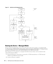
... or VT100 terminal emulator via the RS-232 crossover cable. 2 Locate an AC power receptacle. 40 Dell PowerConnect 28xx Systems User Guide To change between managed and unmanaged modes, press the Mode Button for less than seven seconds. The PowerConnect 2808/16/24/48 models include a built-in this section refers to the device when set...
... or VT100 terminal emulator via the RS-232 crossover cable. 2 Locate an AC power receptacle. 40 Dell PowerConnect 28xx Systems User Guide To change between managed and unmanaged modes, press the Mode Button for less than seven seconds. The PowerConnect 2808/16/24/48 models include a built-in this section refers to the device when set...
User's Guide
Page 41
...be managed (by default, every external and internal port is a member of a VT100 terminal device. (Press the key several times to verify that the prompt displays correctly.) The initial device configuration is through an interface defined during the initial configuration. Dell PowerConnect 28xx ...manually through the initial device configuration, and gets the system up and running as quickly as a Managed Mode switch. Managed Mode The information and procedures described in Unmanaged Mode. POST runs every time the device is initialized and checks hardware components to the dewvice when ...
...be managed (by default, every external and internal port is a member of a VT100 terminal device. (Press the key several times to verify that the prompt displays correctly.) The initial device configuration is through an interface defined during the initial configuration. Dell PowerConnect 28xx ...manually through the initial device configuration, and gets the system up and running as quickly as a Managed Mode switch. Managed Mode The information and procedures described in Unmanaged Mode. POST runs every time the device is initialized and checks hardware components to the dewvice when ...
User's Guide
Page 49
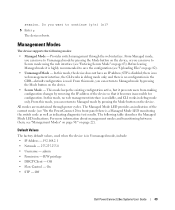
... maintained through the web interface. The following modes: • Managed Mode - For more information about management modes and transitioning between them, see "Entering Secure Mode" on the device. • Secure Mode - admin • Permission - R/W privilege • DHCP Client - Off Dell PowerConnect 28xx Systems User Guide 49 session. Provides switch management through power cycles. STP is available, and CLI works in...
... maintained through the web interface. The following modes: • Managed Mode - For more information about management modes and transitioning between them, see "Entering Secure Mode" on the device. • Secure Mode - admin • Permission - R/W privilege • DHCP Client - Off Dell PowerConnect 28xx Systems User Guide 49 session. Provides switch management through power cycles. STP is available, and CLI works in...
User's Guide
Page 50
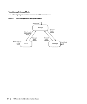
Transitioning Between Management Modes 50 Dell PowerConnect 28xx Systems User Guide Transitioning Between Modes The following diagram summarizes movement between modes: Figure 4-2.
Transitioning Between Management Modes 50 Dell PowerConnect 28xx Systems User Guide Transitioning Between Modes The following diagram summarizes movement between modes: Figure 4-2.
User's Guide
Page 51
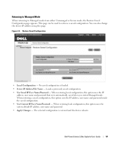
...saved configuration, this option uses the system default IP address, user name and password. • Apply Changes - Returning to Managed Mode When returning to retrieve a saved configuration. This page can also change the device IP address using this option uses the IP ... - You can be used to Managed mode from either Unmanaged or Secure mode, the Restore Saved Configuration page appears. The selected configuration is loaded. • Server IP Address/File Name - Figure 4-3. When restoring local configuration, this page. Dell PowerConnect 28xx Systems User Guide 51
...saved configuration, this option uses the system default IP address, user name and password. • Apply Changes - Returning to Managed Mode When returning to retrieve a saved configuration. This page can also change the device IP address using this option uses the IP ... - You can be used to Managed mode from either Unmanaged or Secure mode, the Restore Saved Configuration page appears. The selected configuration is loaded. • Server IP Address/File Name - Figure 4-3. When restoring local configuration, this page. Dell PowerConnect 28xx Systems User Guide 51
User's Guide
Page 56
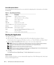
... of the following : Table 5-4. Show All Displays the device tables. Refresh Refreshes device information. For information about management modes, see "Password Recovery. The Dell PowerConnect OpenManage™ Switch Administrator home page opens. Draw Creates statistics charts on page 49. 4 Click OK. Access ...Levels When you login to the device, you : 56 Dell PowerConnect 28xx Systems User Guide Device Management Buttons Button Description Apply Changes Applies changes to you are both case sensitive and alpha-numeric. Left arrow/...
... of the following : Table 5-4. Show All Displays the device tables. Refresh Refreshes device information. For information about management modes, see "Password Recovery. The Dell PowerConnect OpenManage™ Switch Administrator home page opens. Draw Creates statistics charts on page 49. 4 Click OK. Access ...Levels When you login to the device, you : 56 Dell PowerConnect 28xx Systems User Guide Device Management Buttons Button Description Apply Changes Applies changes to you are both case sensitive and alpha-numeric. Left arrow/...
User's Guide
Page 63
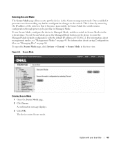
... power cycles just like in the tree view. For information about management modes, see "Managing Files" on page 49. Secure Mode Entering Secure Mode 1 Open the Secure Mode page. 2 Click Secure. For information about saving Configuration files, see "Management Modes" on page 80. To exit Secure Mode, press the Managed Mode button on the device to the switch. Figure 6-5. Entering Secure...
... power cycles just like in the tree view. For information about management modes, see "Managing Files" on page 49. Secure Mode Entering Secure Mode 1 Open the Secure Mode page. 2 Click Secure. For information about saving Configuration files, see "Management Modes" on page 80. To exit Secure Mode, press the Managed Mode button on the device to the switch. Figure 6-5. Entering Secure...
User's Guide
Page 157
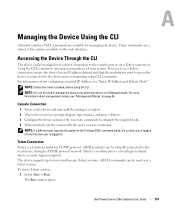
...is logged in. For more information about configuring an initial IP Address, see "Management Modes" on page 49. NOTE: If a different user logs into the system in Managed mode. For information about management modes, see "Static IP Address and Subnet Mask." NOTE: Ensure the client is ... through a TCP/IP protocol network. The Run window opens. These commands are a subset of CLI commands are available for managing the device. A Dell PowerConnect 28xx Systems User Guide 157 Telnet Connection Telnet is complete. 2 When the Console> prompt displays, type enable and press ....
...is logged in. For more information about configuring an initial IP Address, see "Management Modes" on page 49. NOTE: If a different user logs into the system in Managed mode. For information about management modes, see "Static IP Address and Subnet Mask." NOTE: Ensure the client is ... through a TCP/IP protocol network. The Run window opens. These commands are a subset of CLI commands are available for managing the device. A Dell PowerConnect 28xx Systems User Guide 157 Telnet Connection Telnet is complete. 2 When the Console> prompt displays, type enable and press ....


