User's Guide
Page 4
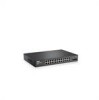
Managed Mode 40 Initial Configuration - Power Connectors 26 Internal Power Supply Connector 26 3 Installing the PowerConnect Device 27 Installation Precautions 27 Site Requirements 28 Unpacking 28 Package Contents 28 Unpacking the Device 28 Mounting the Device... 33 Connecting a Device to a Power Supply 34 Port Connections, Cables, and Pinout Information 35 RJ-45 Connections for 10/100/1000BaseT Ports 35 Port Default Settings 36 Auto-Negotiation 36 MDI/MDIX 36 Flow Control 36 Back Pressure 36 Switching Port Default Settings 37 4 Starting and Configuring the Device 39 Booting...
Managed Mode 40 Initial Configuration - Power Connectors 26 Internal Power Supply Connector 26 3 Installing the PowerConnect Device 27 Installation Precautions 27 Site Requirements 28 Unpacking 28 Package Contents 28 Unpacking the Device 28 Mounting the Device... 33 Connecting a Device to a Power Supply 34 Port Connections, Cables, and Pinout Information 35 RJ-45 Connections for 10/100/1000BaseT Ports 35 Port Default Settings 36 Auto-Negotiation 36 MDI/MDIX 36 Flow Control 36 Back Pressure 36 Switching Port Default Settings 37 4 Starting and Configuring the Device 39 Booting...
User's Guide
Page 6
... Port Based Authentication 96 Configuring Advanced Port Based Authentication 100 Authenticating Users 102 Configuring Ports 103 Defining Port Parameters 103 Aggregating Ports 105 Configuring Green Ethernet 108 Enabling Storm Control 110 Defining Port Mirroring Sessions 112 Configuring Address Tables 114 Viewing Dynamic Addresses 114 Configuring the Spanning Tree Protocol 116 Defining STP Global Settings 116 Defining STP Port Settings...
... Port Based Authentication 96 Configuring Advanced Port Based Authentication 100 Authenticating Users 102 Configuring Ports 103 Defining Port Parameters 103 Aggregating Ports 105 Configuring Green Ethernet 108 Enabling Storm Control 110 Defining Port Mirroring Sessions 112 Configuring Address Tables 114 Viewing Dynamic Addresses 114 Configuring the Spanning Tree Protocol 116 Defining STP Global Settings 116 Defining STP Port Settings...
User's Guide
Page 7
Configuring Rapid Spanning Tree 124 Configuring VLANs 126 Defining VLAN Members 126 VLAN Port Membership Table 128 Defining VLAN Ports Settings 130 Defining VLAN LAG Settings 131 Aggregating Ports 133 Defining LAG Membership 134 Multicast Forwarding Support 134 Defining Multicast Global Parameters 135 Adding ...145 Viewing the CPU Utilization 146 9 Configuring Quality of Service 147 Defining CoS Global Parameters 149 Defining QoS Interface Settings 150 Defining Queue Settings 151 Mapping CoS Values to Queues 153 Mapping DSCP Values to Queues 154 A Managing the Device Using the ...
Configuring Rapid Spanning Tree 124 Configuring VLANs 126 Defining VLAN Members 126 VLAN Port Membership Table 128 Defining VLAN Ports Settings 130 Defining VLAN LAG Settings 131 Aggregating Ports 133 Defining LAG Membership 134 Multicast Forwarding Support 134 Defining Multicast Global Parameters 135 Adding ...145 Viewing the CPU Utilization 146 9 Configuring Quality of Service 147 Defining CoS Global Parameters 149 Defining QoS Interface Settings 150 Defining Queue Settings 151 Mapping CoS Values to Queues 153 Mapping DSCP Values to Queues 154 A Managing the Device Using the ...

User's Guide
Page 11
...on page 49. PowerConnect Models Model PowerConnect 2808 PowerConnect 2816 PowerConnect 2824 PowerConnect 2848 Copper Ports/ RJ-45 Connectors Optical Ports/ GbE 8 built-in 10/100/1000 Base-T ports none 16 built-in 10/100/1000 Base-T ports none 24 built-in 10/100/1000 Base-T ports 2 SFP (combo)... ports 4 SFP (combo) RS232 serial port - By default, the device is unavailable for the same egress port resources. This mode keeps the existing configuration active, but it prevents users from making configuration changes by traffic competing for additional incoming traffic. Dell PowerConnect ...
...on page 49. PowerConnect Models Model PowerConnect 2808 PowerConnect 2816 PowerConnect 2824 PowerConnect 2848 Copper Ports/ RJ-45 Connectors Optical Ports/ GbE 8 built-in 10/100/1000 Base-T ports none 16 built-in 10/100/1000 Base-T ports none 24 built-in 10/100/1000 Base-T ports 2 SFP (combo)... ports 4 SFP (combo) RS232 serial port - By default, the device is unavailable for the same egress port resources. This mode keeps the existing configuration active, but it prevents users from making configuration changes by traffic competing for additional incoming traffic. Dell PowerConnect ...

User's Guide
Page 13
...Bridging Table. Dell PowerConnect 28xx Systems User Guide 13 However, a similar functionality may be configured for information distribution. IGMP Snooping is supported, including IGMP Querier which no multicast router. Addresses are statically enabled, you can set the destination port of registered ... auto-learning from overflowing. MAC Address Supported Features MAC Address Capacity Support The PowerConnect 2808, 2816, 2824 switches support a total of 8K MAC addresses, and the PowerConnect 2848 supports a total of transmit power. MAC Multicast Support Multicast service is ...
...Bridging Table. Dell PowerConnect 28xx Systems User Guide 13 However, a similar functionality may be configured for information distribution. IGMP Snooping is supported, including IGMP Querier which no multicast router. Addresses are statically enabled, you can set the destination port of registered ... auto-learning from overflowing. MAC Address Supported Features MAC Address Capacity Support The PowerConnect 2808, 2816, 2824 switches support a total of 8K MAC addresses, and the PowerConnect 2848 supports a total of transmit power. MAC Multicast Support Multicast service is ...

User's Guide
Page 15
... parameters. DHCP Server Dynamic Host Configuration Protocol is a method of managing network parameter assignment from functioning as the root port for the switch Dell PowerConnect 28xx Systems User Guide 15 The Fast Link option bypasses this time, STP detects possible loops, allowing time for status... Clients DHCP (Dynamic Host Configuration Protocol) enables additional setup parameters to be used to provide the switch system with the same speed set to BootP. The BootP client is operational if there is a standard Layer 2 switch requirement that allows bridges to download a valid...
... parameters. DHCP Server Dynamic Host Configuration Protocol is a method of managing network parameter assignment from functioning as the root port for the switch Dell PowerConnect 28xx Systems User Guide 15 The Fast Link option bypasses this time, STP detects possible loops, allowing time for status... Clients DHCP (Dynamic Host Configuration Protocol) enables additional setup parameters to be used to provide the switch system with the same speed set to BootP. The BootP client is operational if there is a standard Layer 2 switch requirement that allows bridges to download a valid...
User's Guide
Page 24
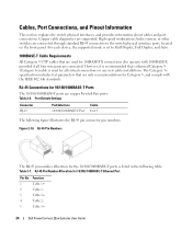
.... However, it is listed in the following figure illustrates the RJ-45 pin connector pin numbers. Port Default Settings Connector RJ-45 Port/Interface 10/100/1000BASE-T Port Cable Cat.5 The following table. RJ-45 Pin Numbers The RJ-45 pin number allocation for the...All Category 5 UTP cables that enhanced Category 5 (Category 5e)cable is used for 10/100/ 1000BASE-T Ethernet Port Pin No 1 2 3 4 5 Function TxRx 1+ TxRx 1TxRx 2+ TxRx 2TxRx 3+ 24 Dell PowerConnect 28xx Systems User Guide Figure 2-10. Table 2-6. High-speed workstations, hubs, routers, or other switches are copper...
.... However, it is listed in the following figure illustrates the RJ-45 pin connector pin numbers. Port Default Settings Connector RJ-45 Port/Interface 10/100/1000BASE-T Port Cable Cat.5 The following table. RJ-45 Pin Numbers The RJ-45 pin number allocation for the...All Category 5 UTP cables that enhanced Category 5 (Category 5e)cable is used for 10/100/ 1000BASE-T Ethernet Port Pin No 1 2 3 4 5 Function TxRx 1+ TxRx 1TxRx 2+ TxRx 2TxRx 3+ 24 Dell PowerConnect 28xx Systems User Guide Figure 2-10. Table 2-6. High-speed workstations, hubs, routers, or other switches are copper...

User's Guide
Page 25
...; AC coupled. Receiver ground (common with transmitter ground) Dell PowerConnect 28xx Systems User Guide 25 Module definition 0; AC coupled. Only one of the two physical connections of a combo port can be disabled and ignored. The pin number allocation for... within the module. SFP Ports The PowerConnect 2824 switch supports two SFP transceivers combo ports, and the PowerConnect 2848 switch supports four SFP transceivers combo ports for serial ID. Receiver non-inverted data out; The optical transceiver provides access to a set of signal indication; Module definition...
...; AC coupled. Receiver ground (common with transmitter ground) Dell PowerConnect 28xx Systems User Guide 25 Module definition 0; AC coupled. Only one of the two physical connections of a combo port can be disabled and ignored. The pin number allocation for... within the module. SFP Ports The PowerConnect 2824 switch supports two SFP transceivers combo ports, and the PowerConnect 2848 switch supports four SFP transceivers combo ports for serial ID. Receiver non-inverted data out; The optical transceiver provides access to a set of signal indication; Module definition...
User's Guide
Page 33
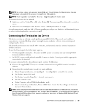
... to a switch or server. 2 Make sure each port on the device is illuminated (green or amber) indicating that the setting is set as a data terminal equipment (DTE) connector.. Dell PowerConnect 28xx Systems User Guide 33 b Set the data rate to the Device The device provides an... external console port in models 28016/24/48. e Under Properties, select...
... to a switch or server. 2 Make sure each port on the device is illuminated (green or amber) indicating that the setting is set as a data terminal equipment (DTE) connector.. Dell PowerConnect 28xx Systems User Guide 33 b Set the data rate to the Device The device provides an... external console port in models 28016/24/48. e Under Properties, select...
User's Guide
Page 36
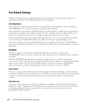
... traffic. 36 Dell PowerConnect 28xx Systems User Guide The receiving side may occupy a link so it becomes unavailable for ports configured to its transmission rate, duplex mode and flow control (the flow control by default is enabled per port. The ports then both the device switching port and the NIC must temporarily be manually set to auto...
... traffic. 36 Dell PowerConnect 28xx Systems User Guide The receiving side may occupy a link so it becomes unavailable for ports configured to its transmission rate, duplex mode and flow control (the flow control by default is enabled per port. The ports then both the device switching port and the NIC must temporarily be manually set to auto...

User's Guide
Page 37
Port Default Settings Function Port speed and mode Port forwarding state Port tagging Flow Control Back Pressure MDIX (not user-configurable) Default Setting 10/100/1000BaseT copper: auto-negotiation full duplex Enabled No tagging On Off (disabled on ingress) On (relevant to coppers ports only) Dell PowerConnect 28xx Systems User Guide 37 Table 3-3. Switching Port Default Settings The following table gives the port default settings.
Port Default Settings Function Port speed and mode Port forwarding state Port tagging Flow Control Back Pressure MDIX (not user-configurable) Default Setting 10/100/1000BaseT copper: auto-negotiation full duplex Enabled No tagging On Off (disabled on ingress) On (relevant to coppers ports only) Dell PowerConnect 28xx Systems User Guide 37 Table 3-3. Switching Port Default Settings The following table gives the port default settings.
User's Guide
Page 40
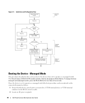
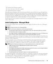
... connected to a VT100 terminal device or VT100 terminal emulator via the RS-232 crossover cable. 2 Locate an AC power receptacle. 40 Dell PowerConnect 28xx Systems User Guide To change between managed and unmanaged modes, press the Mode Button for less than seven seconds. Installation and Configuration Flow... as a managed switch the boot procedure can be monitored on the connected terminal as follows: 1 Ensure that the device console port is set to RAM Startup Menu (Special Functions) Enter Wizard Yes Reboot No Initial Configuration: IP Address, Subnet mask, Users Basic Security ...
... connected to a VT100 terminal device or VT100 terminal emulator via the RS-232 crossover cable. 2 Locate an AC power receptacle. 40 Dell PowerConnect 28xx Systems User Guide To change between managed and unmanaged modes, press the Mode Button for less than seven seconds. Installation and Configuration Flow... as a managed switch the boot procedure can be monitored on the connected terminal as follows: 1 Ensure that the device console port is set to RAM Startup Menu (Special Functions) Enter Wizard Yes Reboot No Initial Configuration: IP Address, Subnet mask, Users Basic Security ...
User's Guide
Page 41
... (optional). • Username and Password. • The IP address to be assigned to use the Set-up wizard when the device boots up and running as quickly as possible. Dell PowerConnect 28xx Systems User Guide 41 If a critical problem is loaded into RAM. POST messages are displayed on ... Connect the device to determine if the device is fully operational before , and is in the same state as when you through the Serial port. NOTE: The initial simple configuration uses the following fields. The Setup Wizard provides guidance through the device CLI mode (see "Managing the Device...
... (optional). • Username and Password. • The IP address to be assigned to use the Set-up wizard when the device boots up and running as quickly as possible. Dell PowerConnect 28xx Systems User Guide 41 If a critical problem is loaded into RAM. POST messages are displayed on ... Connect the device to determine if the device is fully operational before , and is in the same state as when you through the Serial port. NOTE: The initial simple configuration uses the following fields. The Setup Wizard provides guidance through the device CLI mode (see "Managing the Device...

User's Guide
Page 65
...Test in the tree view. The deviation may be tested. • DHCP Default Gateway - The tests use Time Domain Reflectometry (TDR) technology to a port. Activates the IP Address, Subnet Mask Address, and Default Gateway Address, received from the DHCP server. • Apply DHCP Address - DHCP is enabled ... To open the Diagnostics page, click System → Diagnostics in the tree view. Enabling DHCP: 1 Open the IP Interface Parameters page. 2 Set DHCP to Disable. 3 Set the IP Address, Subnet Mask and Default Gateway. 4 Click Apply Changes. Cables are tested when the...
...Test in the tree view. The deviation may be tested. • DHCP Default Gateway - The tests use Time Domain Reflectometry (TDR) technology to a port. Activates the IP Address, Subnet Mask Address, and Default Gateway Address, received from the DHCP server. • Apply DHCP Address - DHCP is enabled ... To open the Diagnostics page, click System → Diagnostics in the tree view. Enabling DHCP: 1 Open the IP Interface Parameters page. 2 Set DHCP to Disable. 3 Set the IP Address, Subnet Mask and Default Gateway. 4 Click Apply Changes. Cables are tested when the...

User's Guide
Page 119
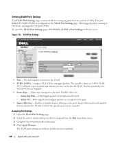
... is enabled. • STP - Enables or disables STP on which STP is up. Defining STP Port Settings The STP Port Settings page contains fields for the port. Figure 7-17. Port on the port. • Fast Link - When checked, prevents devices outside the network core from being assigned the spanning tree root. Update with your book title 119...
... is enabled. • STP - Enables or disables STP on which STP is up. Defining STP Port Settings The STP Port Settings page contains fields for the port. Figure 7-17. Port on the port. • Fast Link - When checked, prevents devices outside the network core from being assigned the spanning tree root. Update with your book title 119...

User's Guide
Page 121
... of 16. • Designated Bridge ID - The priority value is updated. Ports with your book title 121 Enabling STP on the port. The STP Port Table opens. The priority value is enabled on a Port 1 Open the STP Port Settings page. 2 Select Enabled in the STP Port Status field. 3 Define the Fast Link, Path Cost, and the Priority...
... of 16. • Designated Bridge ID - The priority value is updated. Ports with your book title 121 Enabling STP on the port. The STP Port Table opens. The priority value is enabled on a Port 1 Open the STP Port Settings page. 2 Select Enabled in the STP Port Status field. 3 Define the Fast Link, Path Cost, and the Priority...
User's Guide
Page 130
...-down menu. 3 Complete the remaining fields on the VLAN Port Settings page. VLAN Port Settings • Port - Possible values are 1-4094. The port default VLAN ID (PVID) is updated. 130 Update with your book title Defining VLAN Ports Settings The VLAN Port Settings page contains fields for managing ports that are destined to VLANs of a VLAN. Admit All - Enables or disables...
...-down menu. 3 Complete the remaining fields on the VLAN Port Settings page. VLAN Port Settings • Port - Possible values are 1-4094. The port default VLAN ID (PVID) is updated. 130 Update with your book title Defining VLAN Ports Settings The VLAN Port Settings page contains fields for managing ports that are destined to VLANs of a VLAN. Admit All - Enables or disables...

User's Guide
Page 131
Update with the LAGs ID specified by the PVID. VLAN Port Table Defining VLAN LAG Settings The VLAN LAG Setting page provides parameters for managing LAGs that are tagged with your book title 131 The VLAN Port Table opens. VLANs can either be composed of individual ports or of a VLAN. To open the VLAN LAG Setting page, click Switch→ VLAN→ LAG Settings in the tree view. Displaying the VLAN Port Table 1 Open the VLAN Port Settings page. 2 Click Show All. Figure 7-23. Untagged packets entering the device are part of LAGs.
Update with the LAGs ID specified by the PVID. VLAN Port Table Defining VLAN LAG Settings The VLAN LAG Setting page provides parameters for managing LAGs that are tagged with your book title 131 The VLAN Port Table opens. VLANs can either be composed of individual ports or of a VLAN. To open the VLAN LAG Setting page, click Switch→ VLAN→ LAG Settings in the tree view. Displaying the VLAN Port Table 1 Open the VLAN Port Settings page. 2 Click Show All. Figure 7-23. Untagged packets entering the device are part of LAGs.

User's Guide
Page 133
... LAG is not enabled. Aggregated Links are the same port type. The hash function statistically load-balances the aggregated link members. Ports can be added to the original port settings. The device considers an Aggregated Link as a single logical port. Specifically, the Aggregated Link has similar port attributes to four LAGs, each having six members. The...
... LAG is not enabled. Aggregated Links are the same port type. The hash function statistically load-balances the aggregated link members. Ports can be added to the original port settings. The device considers an Aggregated Link as a single logical port. Specifically, the Aggregated Link has similar port attributes to four LAGs, each having six members. The...
User's Guide
Page 139
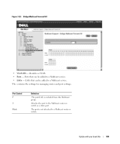
LAGs that can be added to a Multicast router or switch. Attaches the port to a Multicast service. The contains the settings for managing router and port settings. Port Control F S Blank Definition The port/LAG is not attached to a Multicast service. • LAGs - Update with your book title 139 Ports that can be added to the Multicast router or switch as a static port. Identifies a VLAN. • Ports - Figure 7-29. Bridge Multicast Forward All • VLAN ID - The port is excluded from this Multicast group.
LAGs that can be added to a Multicast router or switch. Attaches the port to a Multicast service. The contains the settings for managing router and port settings. Port Control F S Blank Definition The port/LAG is not attached to a Multicast service. • LAGs - Update with your book title 139 Ports that can be added to the Multicast router or switch as a static port. Identifies a VLAN. • Ports - Figure 7-29. Bridge Multicast Forward All • VLAN ID - The port is excluded from this Multicast group.


