
User's Guide
Page 9
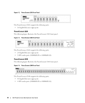
... requires high performance network connectivity along with advanced web management features. PowerConnect 2808 The following figure illustrates the PowerConnect 2816 front panel. Dell PowerConnect 28xx Systems User Guide 9 PowerConnect 2808 Front Panel 1 The PowerConnect 2808 supports the following ports: • 8 Gigabit Ethernet copper ports PowerConnect 2816 The following figure illustrates the PowerConnect 2808 front panel. The switches are designed to medium business that require...
... requires high performance network connectivity along with advanced web management features. PowerConnect 2808 The following figure illustrates the PowerConnect 2816 front panel. Dell PowerConnect 28xx Systems User Guide 9 PowerConnect 2808 Front Panel 1 The PowerConnect 2808 supports the following ports: • 8 Gigabit Ethernet copper ports PowerConnect 2816 The following figure illustrates the PowerConnect 2808 front panel. The switches are designed to medium business that require...
User's Guide
Page 10
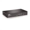
... Ethernet copper ports • 2 SFP combo ports (1000BASE-SX or 1000BASE-LX) PowerConnect 2848 The following ports: • 48 Gigabit Ethernet copper ports • 4 SFP combo ports (1000BASE-SX or 1000BASE-LX) 10 Dell PowerConnect 28xx Systems User Guide Figure 1-2. PowerConnect 2816 Front Panel The PowerConnect 2816 supports the following ports: • 16 Gigabit Ethernet copper ports...
... Ethernet copper ports • 2 SFP combo ports (1000BASE-SX or 1000BASE-LX) PowerConnect 2848 The following ports: • 48 Gigabit Ethernet copper ports • 4 SFP combo ports (1000BASE-SX or 1000BASE-LX) 10 Dell PowerConnect 28xx Systems User Guide Figure 1-2. PowerConnect 2816 Front Panel The PowerConnect 2816 supports the following ports: • 16 Gigabit Ethernet copper ports...

User's Guide
Page 11
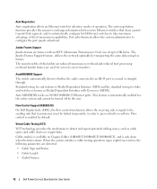
...or Back Pressure is active on a port where the HOL blocking prevention mechanism is disabled on page 49. Dell PowerConnect 28xx Systems User Guide 11 This mode keeps the existing configuration active, but it is set to OFF. Back Pressure Support On half... 1 External console port 2 Features General Features Management Modes The device supports the following table summarizes the PowerConnect models. PowerConnect Models Model PowerConnect 2808 PowerConnect 2816 PowerConnect 2824 PowerConnect 2848 Copper Ports/ RJ-45 Connectors Optical Ports/ GbE 8 built-in 10/100/1000 Base-T ports...
...or Back Pressure is active on a port where the HOL blocking prevention mechanism is disabled on page 49. Dell PowerConnect 28xx Systems User Guide 11 This mode keeps the existing configuration active, but it is set to OFF. Back Pressure Support On half... 1 External console port 2 Features General Features Management Modes The device supports the following table summarizes the PowerConnect models. PowerConnect Models Model PowerConnect 2808 PowerConnect 2816 PowerConnect 2824 PowerConnect 2848 Copper Ports/ RJ-45 Connectors Optical Ports/ GbE 8 built-in 10/100/1000 Base-T ports...
User's Guide
Page 12
...is automatically enabled for hubs and switches is crossed or straight through. When the system initiates a cable-testing operation, upon explicit user action, the following parameters are frames with Crossover (MDIX). Cable analysis is available on 10/100/1000BASE-T Ethernet ports. Port...: • Cable Type and Status • Cable Length • Fault-Distance 12 Dell PowerConnect 28xx Systems User Guide The Jumbo Frames Support feature, utilizes the network optimally by the user. The main benefits of up to detect and report potential cabling issues, such as Media...
...is automatically enabled for hubs and switches is crossed or straight through. When the system initiates a cable-testing operation, upon explicit user action, the following parameters are frames with Crossover (MDIX). Cable analysis is available on 10/100/1000BASE-T Ethernet ports. Port...: • Cable Type and Status • Cable Length • Fault-Distance 12 Dell PowerConnect 28xx Systems User Guide The Jumbo Frames Support feature, utilizes the network optimally by the user. The main benefits of up to detect and report potential cabling issues, such as Media...

User's Guide
Page 13
... of Ethernet connections. MAC Multicast Support Multicast service is received for untagged frames. Dell PowerConnect 28xx Systems User Guide 13 IGMP Snooping is supported, including IGMP Querier which allows one-to-many and... many-to make networking equipment environmentally friendly, specifically by the device: • Energy-Detect - MAC Address Supported Features MAC Address Capacity Support The PowerConnect 2808, 2816, 2824 switches support a total of 8K MAC addresses, and the PowerConnect...
... of Ethernet connections. MAC Multicast Support Multicast service is received for untagged frames. Dell PowerConnect 28xx Systems User Guide 13 IGMP Snooping is supported, including IGMP Querier which allows one-to-many and... many-to make networking equipment environmentally friendly, specifically by the device: • Energy-Detect - MAC Address Supported Features MAC Address Capacity Support The PowerConnect 2808, 2816, 2824 switches support a total of 8K MAC addresses, and the PowerConnect...
User's Guide
Page 14
...VLAN Supported Features VLAN Support VLANs are collections of this facility are: • Fault tolerance protection from physical link disruption 14 Dell PowerConnect 28xx Systems User Guide The benefits of switching ports that comprise a single broadcast domain. IGMP Snooping Internet Group Membership Protocol (IGMP) Snooping examines ... accept and attempt to a VLAN based on either the VLAN tag or based on the RADIUS server. Link Aggregation The PowerConnect 28xx switches support up to four member ports to all traffic passing through one or more source ports. Port Mirroring The...
...VLAN Supported Features VLAN Support VLANs are collections of this facility are: • Fault tolerance protection from physical link disruption 14 Dell PowerConnect 28xx Systems User Guide The benefits of switching ports that comprise a single broadcast domain. IGMP Snooping Internet Group Membership Protocol (IGMP) Snooping examines ... accept and attempt to a VLAN based on either the VLAN tag or based on the RADIUS server. Link Aggregation The PowerConnect 28xx switches support up to four member ports to all traffic passing through one or more source ports. Port Mirroring The...

User's Guide
Page 15
... bridges to all ports on the default VLAN, until a BootP server replies. During this delay, and can take 30-60 seconds for the switch Dell PowerConnect 28xx Systems User Guide 15 The Dynamic Host Configuration Protocol (DHCP) automates the assignment of a response time for relevant devices to respond. 30-60 seconds is considered too...
... bridges to all ports on the default VLAN, until a BootP server replies. During this delay, and can take 30-60 seconds for the switch Dell PowerConnect 28xx Systems User Guide 15 The Dynamic Host Configuration Protocol (DHCP) automates the assignment of a response time for relevant devices to respond. 30-60 seconds is considered too...

User's Guide
Page 16
... the Simple Network Management Protocol (SNMP), which the system can classify according to view the results, using the Web management interface in the system. 16 Dell PowerConnect 28xx Systems User Guide The system contains an Embedded Web Server (EWS), which serves HTML pages, through TFTP. Class of Service (CoS) Features The...
... the Simple Network Management Protocol (SNMP), which the system can classify according to view the results, using the Web management interface in the system. 16 Dell PowerConnect 28xx Systems User Guide The system contains an Embedded Web Server (EWS), which serves HTML pages, through TFTP. Class of Service (CoS) Features The...

User's Guide
Page 17
...optical ports can operate at 1000 Mbps, full-duplex mode. On the left to indicate the port status. Dell PowerConnect 28xx Systems User Guide 17 Figure 2-1. PowerConnect 2808 Front Panel 2 On the front panel there are eight ports which indicates the Ethernet switch operational status and ...Modes" on the front panel for connecting to reset the device. Hardware Description Switch Port Configurations PowerConnect 28xx Front and Back Panel Port Description The Dell™ PowerConnect™ 28xx switches use 10/100/1000BASE-T ports on page 49. The Gigabit Ethernet ports can...
...optical ports can operate at 1000 Mbps, full-duplex mode. On the left to indicate the port status. Dell PowerConnect 28xx Systems User Guide 17 Figure 2-1. PowerConnect 2808 Front Panel 2 On the front panel there are eight ports which indicates the Ethernet switch operational status and ...Modes" on the front panel for connecting to reset the device. Hardware Description Switch Port Configurations PowerConnect 28xx Front and Back Panel Port Description The Dell™ PowerConnect™ 28xx switches use 10/100/1000BASE-T ports on page 49. The Gigabit Ethernet ports can...

User's Guide
Page 18
...the front panel is the Managed Mode LED which indicates the Ethernet switch operational status and the management mode. PowerConnect 2816 Back Panel 18 Dell PowerConnect 28xx Systems User Guide PowerConnect 2816 Front Panel On the front panel there are 16 ports which are LEDs to reset the device. ...A Mode push-button, located on the right side on the front panel, is powered on page 49. Figure 2-4. PowerConnect 2808 Back Panel ...
...the front panel is the Managed Mode LED which indicates the Ethernet switch operational status and the management mode. PowerConnect 2816 Back Panel 18 Dell PowerConnect 28xx Systems User Guide PowerConnect 2816 Front Panel On the front panel there are 16 ports which are LEDs to reset the device. ...A Mode push-button, located on the right side on the front panel, is powered on page 49. Figure 2-4. PowerConnect 2808 Back Panel ...

User's Guide
Page 19
... the SFP port will be the active port, whereas the RJ-45 port will be used on page 49. NOTE: Only one time. Dell PowerConnect 28xx Systems User Guide 19 If both RJ-45 and SFP ports are LEDs to the SFP (or vice versa) without resetting the device. The Fan LED indicates... status and the management mode. On the front panel is used . A Mode push-button, located on the right side on or not. Figure 2-5. PowerConnect 2824 Front Panel On the front panel there are 24 ports which offers high-speed 1000BASE-SX or 1000BASELX connection. Port features and port controls...
... the SFP port will be the active port, whereas the RJ-45 port will be used on page 49. NOTE: Only one time. Dell PowerConnect 28xx Systems User Guide 19 If both RJ-45 and SFP ports are LEDs to the SFP (or vice versa) without resetting the device. The Fan LED indicates... status and the management mode. On the front panel is used . A Mode push-button, located on the right side on or not. Figure 2-5. PowerConnect 2824 Front Panel On the front panel there are 24 ports which offers high-speed 1000BASE-SX or 1000BASELX connection. Port features and port controls...

User's Guide
Page 20
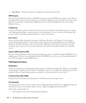
... are present, the SFP port will be the active port, whereas the RJ-45 port will be used at any one time. PowerConnect 2848 Front Panel On the front panel there are logical ports with two physical connections: • An RJ-45 connection for Twisted ...PowerConnect 2824 Back Panel Figure 2-7. The four combo ports are 48 ports, which indicates the Ethernet switch operational status and the management mode. NOTE: The system can be disabled. On the top right side of a combo port can switch from the RJ-45 to right. A Mode push- 20 Dell PowerConnect 28xx Systems User Guide...
... are present, the SFP port will be the active port, whereas the RJ-45 port will be used at any one time. PowerConnect 2848 Front Panel On the front panel there are logical ports with two physical connections: • An RJ-45 connection for Twisted ...PowerConnect 2824 Back Panel Figure 2-7. The four combo ports are 48 ports, which indicates the Ethernet switch operational status and the management mode. NOTE: The system can be disabled. On the top right side of a combo port can switch from the RJ-45 to right. A Mode push- 20 Dell PowerConnect 28xx Systems User Guide...

User's Guide
Page 21
Fans are provided on the front panel is used to reset the device. The back panel contains an AC Power Supply Interface. PowerConnect 2848 Back Panel Physical Dimensions The PowerConnect 2808 switch has the following physical dimensions: • Height - 43.2 mm (1.7008 in.) • Width - 256 mm (10.079 in.) • Depth - 161.7 mm... - 440 mm (17.32 in) • Depth - 255 mm (10.04 in.) LED Definitions The front panel contains LEDs that indicate the status of the PowerConnect 2848 device. Figure 2-8. Dell PowerConnect 28xx Systems User Guide 21
Fans are provided on the front panel is used to reset the device. The back panel contains an AC Power Supply Interface. PowerConnect 2848 Back Panel Physical Dimensions The PowerConnect 2808 switch has the following physical dimensions: • Height - 43.2 mm (1.7008 in.) • Width - 256 mm (10.079 in.) • Depth - 161.7 mm... - 440 mm (17.32 in) • Depth - 255 mm (10.04 in.) LED Definitions The front panel contains LEDs that indicate the status of the PowerConnect 2848 device. Figure 2-8. Dell PowerConnect 28xx Systems User Guide 21

User's Guide
Page 22
... 2-3. The following figure illustrates the RJ-45 10/100/1000BASE-T LEDs. 22 Dell PowerConnect 28xx Systems User Guide Table 2-2. No valid image. For more fans have failed. Fan LED (2824/2848 only) On the PowerConnect 2824 and PowerConnect 2848 front panel there is a Managed Mode LED monitoring the switch node as ...or Secure mode. Speed/Link/Activity is indicated on the left LED and the duplex mode is not turned on. Power LED On the PowerConnect 28xx front panel there is turned on. Table 2-1. Power LED Indications LED Color Green Solid Off Description The switch is a Power LED...
... 2-3. The following figure illustrates the RJ-45 10/100/1000BASE-T LEDs. 22 Dell PowerConnect 28xx Systems User Guide Table 2-2. No valid image. For more fans have failed. Fan LED (2824/2848 only) On the PowerConnect 2824 and PowerConnect 2848 front panel there is a Managed Mode LED monitoring the switch node as ...or Secure mode. Speed/Link/Activity is indicated on the left LED and the duplex mode is not turned on. Power LED On the PowerConnect 28xx front panel there is turned on. Table 2-1. Power LED Indications LED Color Green Solid Off Description The switch is a Power LED...

User's Guide
Page 23
...The port is transmitting or receiving data at 1000 Mbps. SFP Port LED The following table: Table 2-4. The PowerConnect 2808 and PowerConnect 2816 devices have no internal fans. The port is currently transmitting in Half Duplex mode. The port is transmitting... Green Flashing Activity is established. To transition between Managed Mode and Unmanaged (or Secure) Mode and for resetting the device. Dell PowerConnect 28xx Systems User Guide 23 RJ-45 Copper based 10/100/ 1000BASE-T LED Indications LED Color Left LED Green Solid Green Flashing Amber Solid Amber Flashing...
...The port is transmitting or receiving data at 1000 Mbps. SFP Port LED The following table: Table 2-4. The PowerConnect 2808 and PowerConnect 2816 devices have no internal fans. The port is currently transmitting in Half Duplex mode. The port is transmitting... Green Flashing Activity is established. To transition between Managed Mode and Unmanaged (or Secure) Mode and for resetting the device. Dell PowerConnect 28xx Systems User Guide 23 RJ-45 Copper based 10/100/ 1000BASE-T LED Indications LED Color Left LED Green Solid Green Flashing Amber Solid Amber Flashing...
User's Guide
Page 24
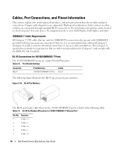
... Category 5e specification includes test parameters that are used for 10/100/ 1000BASE-T Ethernet Port Pin No 1 2 3 4 5 Function TxRx 1+ TxRx 1TxRx 2+ TxRx 2TxRx 3+ 24 Dell PowerConnect 28xx Systems User Guide RJ-45 Pin Number Allocation for all four wire pairs are connected. Cables, Port Connections, and Pinout Information This section explains the switch physical...
... Category 5e specification includes test parameters that are used for 10/100/ 1000BASE-T Ethernet Port Pin No 1 2 3 4 5 Function TxRx 1+ TxRx 1TxRx 2+ TxRx 2TxRx 3+ 24 Dell PowerConnect 28xx Systems User Guide RJ-45 Pin Number Allocation for all four wire pairs are connected. Cables, Port Connections, and Pinout Information This section explains the switch physical...

User's Guide
Page 25
Only one of the two physical connections of a combo port can be disabled and ignored. PowerConnect 2824 switch supports SFP diagnostics. NOTE: If both RJ-45 and SFP ports are present, the SFP port will be the active port.... The system automatically detects the media used at any time. Table 2-7. Receiver ground (common with transmitter ground) Dell PowerConnect 28xx Systems User Guide 25 SFP Ports The PowerConnect 2824 switch supports two SFP transceivers combo ports, and the PowerConnect 2848 switch supports four SFP transceivers combo ports for serial ID. no connection required.
Only one of the two physical connections of a combo port can be disabled and ignored. PowerConnect 2824 switch supports SFP diagnostics. NOTE: If both RJ-45 and SFP ports are present, the SFP port will be the active port.... The system automatically detects the media used at any time. Table 2-7. Receiver ground (common with transmitter ground) Dell PowerConnect 28xx Systems User Guide 25 SFP Ports The PowerConnect 2824 switch supports two SFP transceivers combo ports, and the PowerConnect 2848 switch supports four SFP transceivers combo ports for serial ID. no connection required.
User's Guide
Page 26
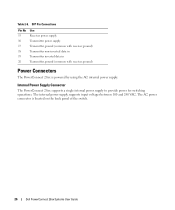
Table 2-8. Internal Power Supply Connector The PowerConnect 28xx supports a single internal power supply to provide power for switching operations. The AC power connector is powered by using the AC internal power supply. ... supply Transmitter ground (common with receiver ground) Transmitter non-inverted data in Transmitter inverted data in Transmitter ground (common with receiver ground) Power Connectors The PowerConnect 28xx is located on the back panel of the switch. 26 Dell PowerConnect 28xx Systems User Guide
Table 2-8. Internal Power Supply Connector The PowerConnect 28xx supports a single internal power supply to provide power for switching operations. The AC power connector is powered by using the AC internal power supply. ... supply Transmitter ground (common with receiver ground) Transmitter non-inverted data in Transmitter inverted data in Transmitter ground (common with receiver ground) Power Connectors The PowerConnect 28xx is located on the back panel of the switch. 26 Dell PowerConnect 28xx Systems User Guide

User's Guide
Page 27
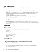
...approved equipment. • Allow the device to prevent it from becoming unstable and/or falling over -current protection. Installing the PowerConnect Device This section contains information about device unpacking, location, installation, and cable connections. Opening or removing covers marked with a ...circuits, wiring, and over . • Ensure that the rack or cabinet housing the device is not restricted. 3 Dell PowerConnect 28xx Systems User Guide 27 To determine the possibility of overloading the supply circuits, add together the ampere ratings of the following points before ...
...approved equipment. • Allow the device to prevent it from becoming unstable and/or falling over -current protection. Installing the PowerConnect Device This section contains information about device unpacking, location, installation, and cable connections. Opening or removing covers marked with a ...circuits, wiring, and over . • Ensure that the rack or cabinet housing the device is not restricted. 3 Dell PowerConnect 28xx Systems User Guide 27 To determine the possibility of overloading the supply circuits, add together the ampere ratings of the following points before ...
User's Guide
Page 28
... While unpacking the device, ensure that the site selected for installation • Documentation CD • Product Information Guide Unpacking the Device To unpack the PowerConnect device: NOTE: Before unpacking the device, inspect the packaging and report any evidence of up to avoid sources ... equipment rack, placed on a tabletop, or mounted on a secure, stable and clean surface. 4 Remove all packing material. 28 Dell PowerConnect 28xx Systems User Guide If the device has two power supplies, the site should have two power outlets with different power feeders. • General - The...
... While unpacking the device, ensure that the site selected for installation • Documentation CD • Product Information Guide Unpacking the Device To unpack the PowerConnect device: NOTE: Before unpacking the device, inspect the packaging and report any evidence of up to avoid sources ... equipment rack, placed on a tabletop, or mounted on a secure, stable and clean surface. 4 Remove all packing material. 28 Dell PowerConnect 28xx Systems User Guide If the device has two power supplies, the site should have two power outlets with different power feeders. • General - The...


