
User's Guide
Page 3
... 9 System Description 9 PowerConnect 2808 9 PowerConnect 2816 9 PowerConnect 2824 10 PowerConnect 2848 10 Summary of PowerConnect Models 11 Features 11 General Features 11 MAC Address Supported Features 13 Layer 2 Features 13 VLAN Supported Features 14 Spanning Tree Protocol Features 15 Class of Service (CoS) Features 16 Ethernet Switch Management Features 16 2 Hardware Description 17 Switch Port Configurations 17 PowerConnect 28xx Front...
... 9 System Description 9 PowerConnect 2808 9 PowerConnect 2816 9 PowerConnect 2824 10 PowerConnect 2848 10 Summary of PowerConnect Models 11 Features 11 General Features 11 MAC Address Supported Features 13 Layer 2 Features 13 VLAN Supported Features 14 Spanning Tree Protocol Features 15 Class of Service (CoS) Features 16 Ethernet Switch Management Features 16 2 Hardware Description 17 Switch Port Configurations 17 PowerConnect 28xx Front...
User's Guide
Page 4
Power Connectors 26 Internal Power Supply Connector 26 3 Installing the PowerConnect Device 27 Installation Precautions 27 Site Requirements 28 Unpacking 28 Package Contents 28 Unpacking the Device 28 Mounting the Device 29 Overview 29 Device Rack...Connections for 10/100/1000BaseT Ports 35 Port Default Settings 36 Auto-Negotiation 36 MDI/MDIX 36 Flow Control 36 Back Pressure 36 Switching Port Default Settings 37 4 Starting and Configuring the Device 39 Booting the Device - Managed Mode 41 Advanced Configuration 44 Retrieving an IP Address From a DHCP Server 45 4 Contents...
Power Connectors 26 Internal Power Supply Connector 26 3 Installing the PowerConnect Device 27 Installation Precautions 27 Site Requirements 28 Unpacking 28 Package Contents 28 Unpacking the Device 28 Mounting the Device 29 Overview 29 Device Rack...Connections for 10/100/1000BaseT Ports 35 Port Default Settings 36 Auto-Negotiation 36 MDI/MDIX 36 Flow Control 36 Back Pressure 36 Switching Port Default Settings 37 4 Starting and Configuring the Device 39 Booting the Device - Managed Mode 41 Advanced Configuration 44 Retrieving an IP Address From a DHCP Server 45 4 Contents...
User's Guide
Page 5
... Download Through TFTP Server 47 Management Modes 49 Default Values 49 Transitioning Between Modes 50 Returning to Managed Mode 51 5 Using Dell OpenManage Switch Administrator 53 Understanding the Interface 53 Device Representation 54 Using the Switch Administrator Buttons 55 Information Buttons 55 Device Management Buttons 56 Starting the Application ...Defining IP Interface Parameters 64 Running Cable Diagnostics 65 Viewing Copper Cable Diagnostics 65 Viewing Optical Transceiver Diagnostics 67 Managing Device Security 69 Defining the Local User Databases 69 Contents 5
... Download Through TFTP Server 47 Management Modes 49 Default Values 49 Transitioning Between Modes 50 Returning to Managed Mode 51 5 Using Dell OpenManage Switch Administrator 53 Understanding the Interface 53 Device Representation 54 Using the Switch Administrator Buttons 55 Information Buttons 55 Device Management Buttons 56 Starting the Application ...Defining IP Interface Parameters 64 Running Cable Diagnostics 65 Viewing Copper Cable Diagnostics 65 Viewing Optical Transceiver Diagnostics 67 Managing Device Security 69 Defining the Local User Databases 69 Contents 5
User's Guide
Page 6
...71 Defining SNMP Parameters 74 Defining SNMP Global Parameters 75 Defining Communities 76 Defining SNMP Notification Recipients 78 Managing Files 80 Downloading Files 80 Uploading Files 82 Restoring Default Settings 83 Defining DHCP Server Settings 83 ...Addresses (Static Hosts 89 Configuring Address Binding 92 Defining Advanced Settings 93 Configuring General Device Parameters 93 7 Configuring Device Switching 95 Configuring Network Security 95 Configuring Port Based Authentication 96 Configuring Advanced Port Based Authentication 100 Authenticating Users 102 Configuring...
...71 Defining SNMP Parameters 74 Defining SNMP Global Parameters 75 Defining Communities 76 Defining SNMP Notification Recipients 78 Managing Files 80 Downloading Files 80 Uploading Files 82 Restoring Default Settings 83 Defining DHCP Server Settings 83 ...Addresses (Static Hosts 89 Configuring Address Binding 92 Defining Advanced Settings 93 Configuring General Device Parameters 93 7 Configuring Device Switching 95 Configuring Network Security 95 Configuring Port Based Authentication 96 Configuring Advanced Port Based Authentication 100 Authenticating Users 102 Configuring...

User's Guide
Page 9
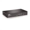
... and maintaining the PowerConnect 2808, PowerConnect 2816, PowerConnect 2824, and PowerConnect 2848 Webmanaged Gigabit Ethernet switches. System Description This section describes the hardware configurations of the PowerConnect 28xx. These PowerConnect devices are managed by Dell's OpenManage Switch Administrator. The switches are ideal for the small to minimize administrative management effort, while enhancing and improving network traffic control. PowerConnect 2808 Front Panel 1 The PowerConnect 2808 supports the following...
... and maintaining the PowerConnect 2808, PowerConnect 2816, PowerConnect 2824, and PowerConnect 2848 Webmanaged Gigabit Ethernet switches. System Description This section describes the hardware configurations of the PowerConnect 28xx. These PowerConnect devices are managed by Dell's OpenManage Switch Administrator. The switches are ideal for the small to minimize administrative management effort, while enhancing and improving network traffic control. PowerConnect 2808 Front Panel 1 The PowerConnect 2808 supports the following...

User's Guide
Page 11
PowerConnect Models Model PowerConnect 2808 PowerConnect 2816 PowerConnect 2824 PowerConnect 2848 Copper Ports/ ...-port basis. Summary of the device so that it becomes inaccessible for configuration. Provides switch management through the web interface. • Unmanaged Mode - By default, the device is ...Management Modes The device supports the following table summarizes the PowerConnect models. This mode keeps the existing configuration active, but it prevents users from making configuration changes by traffic competing for additional incoming traffic. Dell PowerConnect...
PowerConnect Models Model PowerConnect 2808 PowerConnect 2816 PowerConnect 2824 PowerConnect 2848 Copper Ports/ ...-port basis. Summary of the device so that it becomes inaccessible for configuration. Provides switch management through the web interface. • Unmanaged Mode - By default, the device is ...Management Modes The device supports the following table summarizes the PowerConnect models. This mode keeps the existing configuration active, but it prevents users from making configuration changes by traffic competing for additional incoming traffic. Dell PowerConnect...

User's Guide
Page 13
... snooping of unregistered multicast frames. Dell PowerConnect 28xx Systems User Guide 13 Auto-detection of inactivity on their destination MAC address only, regardless of time are stored in Managed and Secure Modes In Managed or Secure mode, the switch system always performs VLAN-aware bridging... Bridging in Unmanaged Mode In Unmanaged Mode, the switch performs classic bridging. MAC Address Supported Features MAC Address Capacity Support The PowerConnect 2808, 2816, 2824 switches support a total of 8K MAC addresses, and the PowerConnect 2848 supports a total of the frame are transmitted...
... snooping of unregistered multicast frames. Dell PowerConnect 28xx Systems User Guide 13 Auto-detection of inactivity on their destination MAC address only, regardless of time are stored in Managed and Secure Modes In Managed or Secure mode, the switch system always performs VLAN-aware bridging... Bridging in Unmanaged Mode In Unmanaged Mode, the switch performs classic bridging. MAC Address Supported Features MAC Address Capacity Support The PowerConnect 2808, 2816, 2824 switches support a total of 8K MAC addresses, and the PowerConnect 2848 supports a total of the frame are transmitted...

User's Guide
Page 15
... Tree Protocol (STP) 802.1d Spanning tree is then used in network topologies where forwarding loops do not occur. Switches exchange configuration messages using specifically formatted frames and selectively enable and disable forwarding on the default VLAN, until a BootP ...a method of managing network parameter assignment from a single DHCP server. • Higher bandwidth connections • Improved bandwidth granularity • High bandwidth server connectivity A LAG is an extension to BootP. DHCP is composed of a response time for the switch Dell PowerConnect 28xx Systems User...
... Tree Protocol (STP) 802.1d Spanning tree is then used in network topologies where forwarding loops do not occur. Switches exchange configuration messages using specifically formatted frames and selectively enable and disable forwarding on the default VLAN, until a BootP ...a method of managing network parameter assignment from a single DHCP server. • Higher bandwidth connections • Improved bandwidth granularity • High bandwidth server connectivity A LAG is an extension to BootP. DHCP is composed of a response time for the switch Dell PowerConnect 28xx Systems User...

User's Guide
Page 16
... (CoS) Features The PowerConnect 28xx system enables users to the destination. The system provides a means to collect the statistics defined in the system. 16 Dell PowerConnect 28xx Systems User Guide Remote Monitoring Remote Monitoring (RMON) is a spin-off of the 802.1Q (VLANs) standard. The PowerConnect 28xx system can be managed from any Web browser...
... (CoS) Features The PowerConnect 28xx system enables users to the destination. The system provides a means to collect the statistics defined in the system. 16 Dell PowerConnect 28xx Systems User Guide Remote Monitoring Remote Monitoring (RMON) is a spin-off of the 802.1Q (VLANs) standard. The PowerConnect 28xx system can be managed from any Web browser...

User's Guide
Page 17
..." on page 49. Dell PowerConnect 28xx Systems User Guide 17 These ports support autonegotiation, duplex mode (Half or Full duplex), and flow control. PowerConnect 2808 Front Panel 2 On the front panel there are eight ports which indicates the Ethernet switch operational status and the management mode. On the left side of the PowerConnect 28xx switches. A Mode push-button...
..." on page 49. Dell PowerConnect 28xx Systems User Guide 17 These ports support autonegotiation, duplex mode (Half or Full duplex), and flow control. PowerConnect 2808 Front Panel 2 On the front panel there are eight ports which indicates the Ethernet switch operational status and the management mode. On the left side of the PowerConnect 28xx switches. A Mode push-button...

User's Guide
Page 18
... Front Panel On the front panel there are 16 ports which indicates the Ethernet switch operational status and the management mode. Figure 2-2. PowerConnect 2808 Back Panel Figure 2-3. Figure 2-4. The Power LED on the front panel indicates whether the device is powered on page 49.... 1 to 16, top down and left side of the front panel is used to transition between them, see "Management Modes" on or not. For more information about management modes and transitioning between management modes and to right. PowerConnect 2816 Back Panel 18 Dell PowerConnect 28xx Systems User Guide
... Front Panel On the front panel there are 16 ports which indicates the Ethernet switch operational status and the management mode. Figure 2-2. PowerConnect 2808 Back Panel Figure 2-3. Figure 2-4. The Power LED on the front panel indicates whether the device is powered on page 49.... 1 to 16, top down and left side of the front panel is used to transition between them, see "Management Modes" on or not. For more information about management modes and transitioning between management modes and to right. PowerConnect 2816 Back Panel 18 Dell PowerConnect 28xx Systems User Guide

User's Guide
Page 19
...Plugable) ports, designated as ports 23 and 24, for swappable optical transceiver, which offers high-speed 1000BASE-SX or 1000BASELX connection. Dell PowerConnect 28xx Systems User Guide 19 NOTE: The system can be disabled. A Mode push-button, located on the right side on the...to 24, top down and left to transition between them, see "Management Modes" on or not. PowerConnect 2824 Front Panel On the front panel there are 24 ports which indicates the Ethernet switch operational status and the management mode. NOTE: Only one time. Figure 2-5. The system automatically detects ...
...Plugable) ports, designated as ports 23 and 24, for swappable optical transceiver, which offers high-speed 1000BASE-SX or 1000BASELX connection. Dell PowerConnect 28xx Systems User Guide 19 NOTE: The system can be disabled. A Mode push-button, located on the right side on the...to 24, top down and left to transition between them, see "Management Modes" on or not. PowerConnect 2824 Front Panel On the front panel there are 24 ports which indicates the Ethernet switch operational status and the management mode. NOTE: Only one time. Figure 2-5. The system automatically detects ...

User's Guide
Page 20
PowerConnect 2848 Front Panel On the front panel there are 48 ports, which indicates the Ethernet switch operational status and the management mode. There are LEDs to indicate the port status. On the top right side of a combo port can switch from the RJ-45 to right. The Fan LED ...connections: • An RJ-45 connection for Twisted Pair (TP) copper cabling. • An SFP port for fiber connection. A Mode push- 20 Dell PowerConnect 28xx Systems User Guide Figure 2-6. On each port, there are four SFP (Small Form-Factor Plugable) ports, designated as ports 45, 46, 47 and...
PowerConnect 2848 Front Panel On the front panel there are 48 ports, which indicates the Ethernet switch operational status and the management mode. There are LEDs to indicate the port status. On the top right side of a combo port can switch from the RJ-45 to right. The Fan LED ...connections: • An RJ-45 connection for Twisted Pair (TP) copper cabling. • An SFP port for fiber connection. A Mode push- 20 Dell PowerConnect 28xx Systems User Guide Figure 2-6. On each port, there are four SFP (Small Form-Factor Plugable) ports, designated as ports 45, 46, 47 and...

User's Guide
Page 21
... the right side on page 49. Dell PowerConnect 28xx Systems User Guide 21 For more information about management modes and transitioning between them, see "Management Modes" on the front panel is used to transition between management modes and to reset the device. Fans... • Depth - 255 mm (10.04 in .) The PowerConnect 2848 switch has the following figure illustrates the back panel of links, power supply, fan status, and Managed Mode status. PowerConnect 2848 Back Panel Physical Dimensions The PowerConnect 2808 switch has the following physical dimensions: • Height - 43.2 mm...
... the right side on page 49. Dell PowerConnect 28xx Systems User Guide 21 For more information about management modes and transitioning between them, see "Management Modes" on the front panel is used to transition between management modes and to reset the device. Fans... • Depth - 255 mm (10.04 in .) The PowerConnect 2848 switch has the following figure illustrates the back panel of links, power supply, fan status, and Managed Mode status. PowerConnect 2848 Back Panel Physical Dimensions The PowerConnect 2808 switch has the following physical dimensions: • Height - 43.2 mm...

User's Guide
Page 22
... 22 Dell PowerConnect 28xx Systems User Guide Table 2-2. Table 2-3. Speed/Link/Activity is indicated on the left LED and the duplex mode is indicated on . The following table describes the Managed Mode LED indications. Table 2-1. Managed Mode LED...PowerConnect 2824 and PowerConnect 2848 front panel there is a Power LED. The following table describes the fan status LED indications. Managed Mode LED On the PowerConnect 28xx front panel there is in progress, firmware loading, or Management Mode transition. Indicates the switch is a Managed Mode LED monitoring the switch...
... 22 Dell PowerConnect 28xx Systems User Guide Table 2-2. Table 2-3. Speed/Link/Activity is indicated on the left LED and the duplex mode is indicated on . The following table describes the Managed Mode LED indications. Table 2-1. Managed Mode LED...PowerConnect 2824 and PowerConnect 2848 front panel there is a Power LED. The following table describes the fan status LED indications. Managed Mode LED On the PowerConnect 28xx front panel there is in progress, firmware loading, or Management Mode transition. Indicates the switch is a Managed Mode LED monitoring the switch...

User's Guide
Page 23
...is established. The PowerConnect 2808 and PowerConnect 2816 devices have no internal fans. Managed Mode Button The PowerConnect 28xx has a Mode push button on page 49. For more information about management modes and transitioning between them, see "Management Modes" on the front panel. Dell PowerConnect 28xx Systems User ... Mbps. To reset the device, press and hold the button for at 1000 Mbps. Switch Ventilation Fan The PowerConnect 2848 switch has three fans and the PowerConnect 2824 switch has one fan for resetting the device. RJ-45 Copper-based 10/100/1000BASE-T LEDs...
...is established. The PowerConnect 2808 and PowerConnect 2816 devices have no internal fans. Managed Mode Button The PowerConnect 28xx has a Mode push button on page 49. For more information about management modes and transitioning between them, see "Management Modes" on the front panel. Dell PowerConnect 28xx Systems User ... Mbps. To reset the device, press and hold the button for at 1000 Mbps. Switch Ventilation Fan The PowerConnect 2848 switch has three fans and the PowerConnect 2824 switch has one fan for resetting the device. RJ-45 Copper-based 10/100/1000BASE-T LEDs...
User's Guide
Page 39
... configuration is recommended that you obtain the most recent revision of the user documentation from http://support.dell.com. The release notes can be used as an unmanaged switch, there is no need for a terminal connection. • A terminal connection is required if the... external connections, procede as follows: • If the device is to be used in a managed mode. NOTE: It is performed. 4 Dell PowerConnect 28xx Systems User Guide 39 NOTE: The PowerConnect 2808 has an internal serial port. Starting and Configuring the Device After completing all external connections, connect ...
... configuration is recommended that you obtain the most recent revision of the user documentation from http://support.dell.com. The release notes can be used as an unmanaged switch, there is no need for a terminal connection. • A terminal connection is required if the... external connections, procede as follows: • If the device is to be used in a managed mode. NOTE: It is performed. 4 Dell PowerConnect 28xx Systems User Guide 39 NOTE: The PowerConnect 2808 has an internal serial port. Starting and Configuring the Device After completing all external connections, connect ...
User's Guide
Page 40
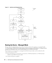
... Loading Program from flash to operate as a managed switch the boot procedure can be monitored on the connected terminal as a managed switch. To change between managed and unmanaged modes, press the Mode Button for less than seven seconds. Managed Mode The procedure described in dual purpose Mode Button. The PowerConnect 2808/16/24/48 models include a built-in... device console port is connected to a VT100 terminal device or VT100 terminal emulator via the RS-232 crossover cable. 2 Locate an AC power receptacle. 40 Dell PowerConnect 28xx Systems User Guide Figure 4-1.
... Loading Program from flash to operate as a managed switch the boot procedure can be monitored on the connected terminal as a managed switch. To change between managed and unmanaged modes, press the Mode Button for less than seven seconds. Managed Mode The procedure described in dual purpose Mode Button. The PowerConnect 2808/16/24/48 models include a built-in... device console port is connected to a VT100 terminal device or VT100 terminal emulator via the RS-232 crossover cable. 2 Locate an AC power receptacle. 40 Dell PowerConnect 28xx Systems User Guide Figure 4-1.
Getting Started Guide
Page 7
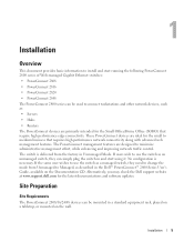
... to use the switch as a managed switch, they can simply plug the switch in and start running the following PowerConnect 2800 series of Web-managed Gigabit Ethernet switches: • PowerConnect 2808 • PowerConnect 2816 • PowerConnect 2824 • PowerConnect 2848 The PowerConnect 2800 series can be used to connect workstations and other network devices, such as described in the Dell™ PowerConnect™ 2800 Series...
... to use the switch as a managed switch, they can simply plug the switch in and start running the following PowerConnect 2800 series of Web-managed Gigabit Ethernet switches: • PowerConnect 2808 • PowerConnect 2816 • PowerConnect 2824 • PowerConnect 2848 The PowerConnect 2800 series can be used to connect workstations and other network devices, such as described in the Dell™ PowerConnect™ 2800 Series...

Getting Started Guide
Page 16
...directly to the Console port on the device, and tighten the captive retaining screws. Go to www.microsoft.com for Emulation mode. The PowerConnect 2808/16/24/48 models include a built-in this section refers to the device when set to operate as follows: a Select the ... VT100 emulation. The Console port connector is a male DB-9 connector, implemented as follows: 1 Ensure that the terminal emulation software is set as a managed switch. To use the Console port, the following : 1 Connect the supplied RS-232 crossover cable to the terminal running VT100 terminal emulation software. •...
...directly to the Console port on the device, and tighten the captive retaining screws. Go to www.microsoft.com for Emulation mode. The PowerConnect 2808/16/24/48 models include a built-in this section refers to the device when set to operate as follows: a Select the ... VT100 emulation. The Console port connector is a male DB-9 connector, implemented as follows: 1 Ensure that the terminal emulation software is set as a managed switch. To use the Console port, the following : 1 Connect the supplied RS-232 crossover cable to the terminal running VT100 terminal emulation software. •...


