Quick Reference Guide
Page 9
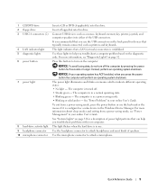
... • Steady green - NOTICE: If your computer. The computer is established. It is recommended that a LAN (network) connection is in a power-saving mode. • Blinking or solid amber - Insert a floppy disk into this drive. 1 CD/DVD drive 2 floppy drive 3 USB 2.0... connectors (2) 4 LAN indicator light 5 diagnostic lights 6 power button 7 power light 8 hard-drive activity light 9 headphone connector 10 microphone connector Insert a CD or DVD (if applicable) into this drive. Press this ...
... • Steady green - NOTICE: If your computer. The computer is established. It is recommended that a LAN (network) connection is in a power-saving mode. • Blinking or solid amber - Insert a floppy disk into this drive. 1 CD/DVD drive 2 floppy drive 3 USB 2.0... connectors (2) 4 LAN indicator light 5 diagnostic lights 6 power button 7 power light 8 hard-drive activity light 9 headphone connector 10 microphone connector Insert a CD or DVD (if applicable) into this drive. Press this ...
Quick Reference Guide
Page 11
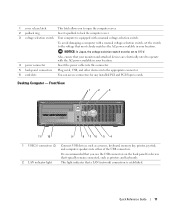
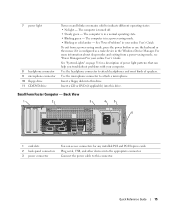
Also, ensure that most closely matches the AC power available in your location. Quick Reference Guide 11 To avoid damaging a computer with a manual voltage-selection switch, set to 115-V. Front View 1 2 3 11 10 9 8 76 5 ...printers and keyboards. 2 LAN indicator light This light indicates that a LAN (network) connection is established. It is equipped with the AC power available in your location. 4 power connector Insert the power cable into this connector. 5 back-panel connectors Plug serial, USB, and other devices into either of the USB connectors. Desktop Computer -...
Also, ensure that most closely matches the AC power available in your location. Quick Reference Guide 11 To avoid damaging a computer with a manual voltage-selection switch, set to 115-V. Front View 1 2 3 11 10 9 8 76 5 ...printers and keyboards. 2 LAN indicator light This light indicates that a LAN (network) connection is established. It is equipped with the AC power available in your location. 4 power connector Insert the power cable into this connector. 5 back-panel connectors Plug serial, USB, and other devices into either of the USB connectors. Desktop Computer -...
Quick Reference Guide
Page 12
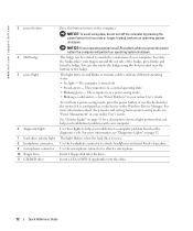
... a CD or DVD (if applicable) into this drive. 12 Quick Reference Guide To rotate the badge, place your online User's Guide. www.dell.com | support.dell.com 3 power button 4 Dell badge 5 power light 6 diagnostic lights 7 hard-drive activity light 8 headphone connector 9 microphone connector 10 floppy drive 11 CD/DVD drive Press this button to help...
... a CD or DVD (if applicable) into this drive. 12 Quick Reference Guide To rotate the badge, place your online User's Guide. www.dell.com | support.dell.com 3 power button 4 Dell badge 5 power light 6 diagnostic lights 7 hard-drive activity light 8 headphone connector 9 microphone connector 10 floppy drive 11 CD/DVD drive Press this button to help...
Quick Reference Guide
Page 13
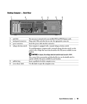
Also, ensure that most closely matches the AC power available in your location. To avoid damaging a computer with a manual voltage-selection switch, set to 115-V. Quick Reference Guide 13 NOTICE: In Japan, the voltage ... access connectors for any installed PCI and PCI Express cards. 2 back-panel connectors Plug serial, USB, and other devices into the appropriate connector. 3 power connector Insert the power cable into this latch to lock the computer cover. 6 cover release latch Use this connector. 4 voltage selection switch Your computer is equipped with the...
Also, ensure that most closely matches the AC power available in your location. To avoid damaging a computer with a manual voltage-selection switch, set to 115-V. Quick Reference Guide 13 NOTICE: In Japan, the voltage ... access connectors for any installed PCI and PCI Express cards. 2 back-panel connectors Plug serial, USB, and other devices into the appropriate connector. 3 power connector Insert the power cable into this latch to lock the computer cover. 6 cover release latch Use this connector. 4 voltage selection switch Your computer is equipped with the...
Quick Reference Guide
Page 14
...system shutdown. You can be rotated to turn off the computer by pressing the power button for devices that you press the power button the computer will perform an operating system shutdown. 3 Dell badge The badge can also rotate the badge using the slot provided near the ... that typically remain connected, such as a mouse, keyboard, memory key, printer, joystick, and computer speakers into either of the USB connectors. 2 power button It is established. 5 diagnostic lights Use these lights to help you troubleshoot a computer problem based on the back panel for 6 seconds or ...
...system shutdown. You can be rotated to turn off the computer by pressing the power button for devices that you press the power button the computer will perform an operating system shutdown. 3 Dell badge The badge can also rotate the badge using the slot provided near the ... that typically remain connected, such as a mouse, keyboard, memory key, printer, joystick, and computer speakers into either of the USB connectors. 2 power button It is established. 5 diagnostic lights Use these lights to help you troubleshoot a computer problem based on the back panel for 6 seconds or ...
Quick Reference Guide
Page 15
...as a wake device in your online User's Guide. To exit from a power-saving mode, see "Power Management" in the Windows Device Manager. Use the microphone connector to attach headphones and most kinds of power light patterns that can access connectors for a description of speakers. Small Form ...is in a normal operating state. • Blinking green - The computer is in a power-saving mode. • Blinking or solid amber - Plug serial, USB, and other devices into this drive. 7 power light 8 headphone connector 9 microphone connector 10 floppy drive 11 CD/DVD drive Turns on...
...as a wake device in your online User's Guide. To exit from a power-saving mode, see "Power Management" in the Windows Device Manager. Use the microphone connector to attach headphones and most kinds of power light patterns that can access connectors for a description of speakers. Small Form ...is in a normal operating state. • Blinking green - The computer is in a power-saving mode. • Blinking or solid amber - Plug serial, USB, and other devices into this drive. 7 power light 8 headphone connector 9 microphone connector 10 floppy drive 11 CD/DVD drive Turns on...
Quick Reference Guide
Page 16
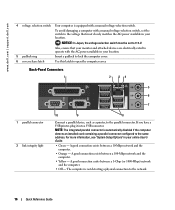
... connector. The computer is not detecting a physical connection to the parallel connector. Also, ensure that most closely matches the AC power available in your location. NOTICE: In Japan, the voltage selection switch must be set the switch to the voltage that your ...card containing a parallel connector configured to open the computer cover. To avoid damaging a computer with a manual voltage-selection switch. www.dell.com | support.dell.com 4 voltage selection switch Your computer is equipped with a manual voltage-selection switch, set to 115-V. For more information, see...
... connector. The computer is not detecting a physical connection to the parallel connector. Also, ensure that most closely matches the AC power available in your location. NOTICE: In Japan, the voltage selection switch must be set the switch to the voltage that your ...card containing a parallel connector configured to open the computer cover. To avoid damaging a computer with a manual voltage-selection switch. www.dell.com | support.dell.com 4 voltage selection switch Your computer is equipped with a manual voltage-selection switch, set to 115-V. For more information, see...
Quick Reference Guide
Page 19
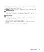
... the electrical outlet before removing the cover. Mini Tower Computer NOTICE: Before touching anything inside your computer from their electrical outlets, and then press the power button to dissipate any static electricity that could harm internal components. 1 Follow the procedures in the following illustration. While you work , periodically touch an unpainted...
... the electrical outlet before removing the cover. Mini Tower Computer NOTICE: Before touching anything inside your computer from their electrical outlets, and then press the power button to dissipate any static electricity that could harm internal components. 1 Follow the procedures in the following illustration. While you work , periodically touch an unpainted...
Quick Reference Guide
Page 24
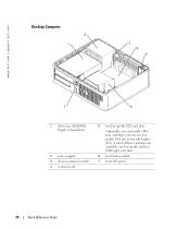
A total of three card slots are available: one lowprofile PCI slot to two full-height slots. www.dell.com | support.dell.com Desktop Computer 2 1 3 4 5 7 6 1 drives bay (CD/DVD, floppy, or hard drive) 2 power supply 3 chassis intrusion switch 4 system board 5 two low-profile PCI card slots Optionally, you can install a PCI riser card that converts one low-profile and two full-height card slots. 6 heat sink assembly 7 front I/O panel 24 Quick Reference Guide
A total of three card slots are available: one lowprofile PCI slot to two full-height slots. www.dell.com | support.dell.com Desktop Computer 2 1 3 4 5 7 6 1 drives bay (CD/DVD, floppy, or hard drive) 2 power supply 3 chassis intrusion switch 4 system board 5 two low-profile PCI card slots Optionally, you can install a PCI riser card that converts one low-profile and two full-height card slots. 6 heat sink assembly 7 front I/O panel 24 Quick Reference Guide
Quick Reference Guide
Page 25
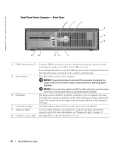
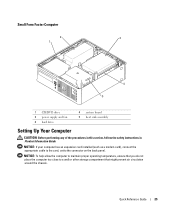
Small Form Factor Computer 2 3 1 4 5 1 CD/DVD drive 2 power supply and fan 3 hard drive 4 system board 5 heat sink assembly Setting Up Your Computer CAUTION: Before performing any of the procedures in this section, follow ...
Small Form Factor Computer 2 3 1 4 5 1 CD/DVD drive 2 power supply and fan 3 hard drive 4 system board 5 heat sink assembly Setting Up Your Computer CAUTION: Before performing any of the procedures in this section, follow ...
Quick Reference Guide
Page 26
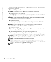
...the monitor cable to verify that came with your monitor for your location. NOTE: Before you have the video connector underneath the back of the power cables to the network adapter connector. Voltage from the following illustrations. 26 Quick Reference Guide NOTICE: To avoid damaging a computer with your computer.... the network connector. Your computer has a manual voltage-selection switch. NOTICE: Do not attempt to operate at the correct operating voltage. www.dell.com | support.dell.com You must complete all the steps to properly set up your computer and operating system.
...the monitor cable to verify that came with your monitor for your location. NOTE: Before you have the video connector underneath the back of the power cables to the network adapter connector. Voltage from the following illustrations. 26 Quick Reference Guide NOTICE: To avoid damaging a computer with your computer.... the network connector. Your computer has a manual voltage-selection switch. NOTICE: Do not attempt to operate at the correct operating voltage. www.dell.com | support.dell.com You must complete all the steps to properly set up your computer and operating system.
Quick Reference Guide
Page 28
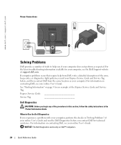
...User's Guide. For information on contacting Dell, see the Dell Support website at support.dell.com. When to help from the same location as expected. See "Finding Information" on Dell™ computers. 28 Quick Reference Guide NOTICE: The Dell Diagnostics works only on page 5 for ..." of your online User's Guide and run the Dell Diagnostics before you contact Dell for your computer, see your computer. www.dell.com | support.dell.com Power Connections Solving Problems Dell provides a number of tools to Use the Dell Diagnostics If you experience a problem with your computer,...
...User's Guide. For information on contacting Dell, see the Dell Support website at support.dell.com. When to help from the same location as expected. See "Finding Information" on Dell™ computers. 28 Quick Reference Guide NOTICE: The Dell Diagnostics works only on page 5 for ..." of your online User's Guide and run the Dell Diagnostics before you contact Dell for your computer, see your computer. www.dell.com | support.dell.com Power Connections Solving Problems Dell provides a number of tools to Use the Dell Diagnostics If you experience a problem with your computer,...
Quick Reference Guide
Page 31
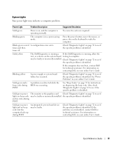
... Lights" on , and the computer is identified. Power Light Problem Description Suggested Resolution Solid green Power is on page 32 to wake the computer. Blinking green The computer is in your online User's Guide. If the computer does not boot, contact Dell for instructions on contacting Dell, see if the specific problem is required.
... Lights" on , and the computer is identified. Power Light Problem Description Suggested Resolution Solid green Power is on page 32 to wake the computer. Blinking green The computer is in your online User's Guide. If the computer does not boot, contact Dell for instructions on contacting Dell, see if the specific problem is required.
Quick Reference Guide
Page 32
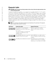
...time, and then turn off " Plug the computer into a working condition, or a possible pre-BIOS failure electrical outlet and press the power has occurred. If the POST portion of system boot completes successfully, all four lights display solid green for computer is in the recovery mode... process completes. When the computer starts normally, the patterns or codes on the lights change as the boot process completes. www.dell.com | support.dell.com Diagnostic Lights CAUTION: Before you troubleshoot a problem, your online User's Guide. 32 Quick Reference Guide NOTE: The orientation ...
...time, and then turn off " Plug the computer into a working condition, or a possible pre-BIOS failure electrical outlet and press the power has occurred. If the POST portion of system boot completes successfully, all four lights display solid green for computer is in the recovery mode... process completes. When the computer starts normally, the patterns or codes on the lights change as the boot process completes. www.dell.com | support.dell.com Diagnostic Lights CAUTION: Before you troubleshoot a problem, your online User's Guide. 32 Quick Reference Guide NOTE: The orientation ...
Quick Reference Guide
Page 33
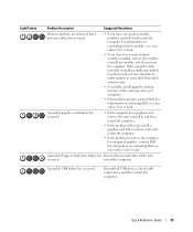
For information on reinstalling memory modules, see your computer. • If the problem persists, contact Dell. Continue until you have identified a faulty module or reinstalled all modules without error. • If available, install properly ...devices, check cable connections, and then restart the computer. Reinstall all power and data cables and occurred. Quick Reference Guide 33 For information on contacting Dell, see your online User's Guide. For information on contacting Dell, see your online User's Guide. Light Pattern Problem Description Suggested Resolution...
For information on reinstalling memory modules, see your computer. • If the problem persists, contact Dell. Continue until you have identified a faulty module or reinstalled all modules without error. • If available, install properly ...devices, check cable connections, and then restart the computer. Reinstall all power and data cables and occurred. Quick Reference Guide 33 For information on contacting Dell, see your online User's Guide. For information on contacting Dell, see your online User's Guide. Light Pattern Problem Description Suggested Resolution...

Quick Reference Guide
Page 35
..., a burst of -day clock stopped Cause Slave interrupt mask register failure Interrupt vector loading failure Keyboard Controller test failure NVRAM power loss Invalid NVRAM configuration Video Memory test failure Screen initialization failure Screen retrace failure Search for video ROM failure No timer tick ...assistance. Beep Codes Your computer might emit a series of beeps during start-up: 1 Write down the beep code. 2 See "Dell Diagnostics" on contacting Dell, see your computer beeps during start-up if the monitor cannot display errors or problems. This series of beeps, called a beep...
..., a burst of -day clock stopped Cause Slave interrupt mask register failure Interrupt vector loading failure Keyboard Controller test failure NVRAM power loss Invalid NVRAM configuration Video Memory test failure Screen initialization failure Screen retrace failure Search for video ROM failure No timer tick ...assistance. Beep Codes Your computer might emit a series of beeps during start-up: 1 Write down the beep code. 2 See "Dell Diagnostics" on contacting Dell, see your computer beeps during start-up if the monitor cannot display errors or problems. This series of beeps, called a beep...
Quick Reference Guide
Page 43
...CD, 5 DSS, 5-6 E error messages beep codes, 35 diagnostic lights, 32 system lights, 31 H hardware beep codes, 35 conflicts, 36 Dell Diagnostics, 28 Hardware Troubleshooter, 36 Help and Support Center, 7 I installing parts before you begin, 18 IRQ conflicts, 36 L labels Microsoft Windows...Tag, 6 lights diagnostic, 32 system, 31 M Microsoft Windows label, 6 O operating system CD, 7 Installation Guide, 7 reinstalling Windows XP, 38 P power light diagnosing problems with, 31 patterns, 9, 12, 15 problems. See troubleshooting Index 43 Index B beep codes, 35 C CDs drivers and utilities, 7 operating...
...CD, 5 DSS, 5-6 E error messages beep codes, 35 diagnostic lights, 32 system lights, 31 H hardware beep codes, 35 conflicts, 36 Dell Diagnostics, 28 Hardware Troubleshooter, 36 Help and Support Center, 7 I installing parts before you begin, 18 IRQ conflicts, 36 L labels Microsoft Windows...Tag, 6 lights diagnostic, 32 system, 31 M Microsoft Windows label, 6 O operating system CD, 7 Installation Guide, 7 reinstalling Windows XP, 38 P power light diagnosing problems with, 31 patterns, 9, 12, 15 problems. See troubleshooting Index 43 Index B beep codes, 35 C CDs drivers and utilities, 7 operating...


