
Quick Reference Guide
Page 3
... Computer 22 Inside Your Computer 23 Mini Tower Computer 23 Desktop Computer 24 Small Form Factor Computer 25 Setting Up Your Computer 25 Solving Problems 28 Dell Diagnostics 28 System Lights 31 Diagnostic Lights 32 Beep Codes 35 Running the Dell™ IDE Hard Drive Diagnostics 36 Resolving Software and Hardware Incompatibilities 36 Using Microsoft® Windows® XP System Restore 36 Reinstalling Microsoft® Windows® XP 38 Using the Drivers and Utilities CD...
... Computer 22 Inside Your Computer 23 Mini Tower Computer 23 Desktop Computer 24 Small Form Factor Computer 25 Setting Up Your Computer 25 Solving Problems 28 Dell Diagnostics 28 System Lights 31 Diagnostic Lights 32 Beep Codes 35 Running the Dell™ IDE Hard Drive Diagnostics 36 Resolving Software and Hardware Incompatibilities 36 Using Microsoft® Windows® XP System Restore 36 Reinstalling Microsoft® Windows® XP 38 Using the Drivers and Utilities CD...
Quick Reference Guide
Page 5
... Guide • How to remove and replace parts • Specifications • How to configure system settings • How to reinstall drivers (see "Using the Drivers and Utilities CD" on page 41), run the Dell Diagnostics (see "Starting the Dell Diagnostics From the Drivers and Utilities CD" on your computer or in the Microsoft® Windows® XP Help and Support Center: 1 Click the Start button and click Help and Support. 2 Click User's and system guides and click User's guides...
... Guide • How to remove and replace parts • Specifications • How to configure system settings • How to reinstall drivers (see "Using the Drivers and Utilities CD" on page 41), run the Dell Diagnostics (see "Starting the Dell Diagnostics From the Drivers and Utilities CD" on your computer or in the Microsoft® Windows® XP Help and Support Center: 1 Click the Start button and click Help and Support. 2 Click User's and system guides and click User's guides...
Quick Reference Guide
Page 6
... installs the updates appropriate for Dell™ 3.5-inch USB floppy drives, Intel® Pentium® M processors, optical drives, and USB devices. This software automatically detects your configuration. 6 Quick Reference Guide www.dell.com | support.dell.com What Are You Looking For? Find It Here • Service Tag and Express Service Code • Microsoft Windows License Label Service Tag and Microsoft Windows License These labels are located on computer configuration, product specifications, and white papers • Downloads - Upgrade...
... installs the updates appropriate for Dell™ 3.5-inch USB floppy drives, Intel® Pentium® M processors, optical drives, and USB devices. This software automatically detects your configuration. 6 Quick Reference Guide www.dell.com | support.dell.com What Are You Looking For? Find It Here • Service Tag and Express Service Code • Microsoft Windows License Label Service Tag and Microsoft Windows License These labels are located on computer configuration, product specifications, and white papers • Downloads - Upgrade...
Quick Reference Guide
Page 7
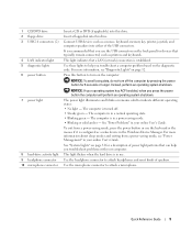
... • Service call status and support history • Top technical issues for the devices that describes your computer. Your operating system product key label is already installed on the operating system you reinstall your operating system, use the optional Drivers and Utilities CD to reinstall drivers for my computer • Frequently asked questions • File downloads • Details on your problem. 4 Follow the instructions on the screen. •...
... • Service call status and support history • Top technical issues for the devices that describes your computer. Your operating system product key label is already installed on the operating system you reinstall your operating system, use the optional Drivers and Utilities CD to reinstall drivers for my computer • Frequently asked questions • File downloads • Details on your problem. 4 Follow the instructions on the screen. •...
Quick Reference Guide
Page 9
... a LAN (network) connection is in the Windows Device Manager. Use the microphone connector to help you use . This light flickers when the hard drive is in your computer. This light indicates that typically remain connected, such as a wake device in a normal operating state. • Blinking green - See "Power Problems" in use the USB connectors on the diagnostic code. Quick Reference Guide 9 NOTICE: To avoid losing data, do not turn on page 32. 1 CD/DVD drive 2 floppy drive 3 USB 2.0 connectors (2) 4 LAN indicator light 5 diagnostic lights 6 power button 7 power light...
... a LAN (network) connection is in the Windows Device Manager. Use the microphone connector to help you use . This light flickers when the hard drive is in your computer. This light indicates that typically remain connected, such as a wake device in a normal operating state. • Blinking green - See "Power Problems" in use the USB connectors on the diagnostic code. Quick Reference Guide 9 NOTICE: To avoid losing data, do not turn on page 32. 1 CD/DVD drive 2 floppy drive 3 USB 2.0 connectors (2) 4 LAN indicator light 5 diagnostic lights 6 power button 7 power light...
Quick Reference Guide
Page 11
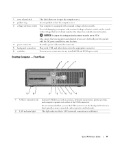
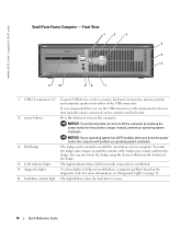
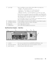
...4 power connector Insert the power cable into this connector. 5 back-panel connectors Plug serial, USB, and other devices into either of the USB connectors. Front View 1 2 3 11 10 9 8 76 5 4 1 USB 2.0 connectors (2) Connect USB devices such as printers and keyboards. 2 LAN indicator light This light indicates that typically remain connected, such as a mouse, keyboard, memory key, printer, joystick, and computer speakers into the appropriate connector. 6 card slots You can access connectors for devices that a LAN (network) connection is recommended that you to open the...
...4 power connector Insert the power cable into this connector. 5 back-panel connectors Plug serial, USB, and other devices into either of the USB connectors. Front View 1 2 3 11 10 9 8 76 5 4 1 USB 2.0 connectors (2) Connect USB devices such as printers and keyboards. 2 LAN indicator light This light indicates that typically remain connected, such as a mouse, keyboard, memory key, printer, joystick, and computer speakers into the appropriate connector. 6 card slots You can access connectors for devices that a LAN (network) connection is recommended that you to open the...
Quick Reference Guide
Page 12
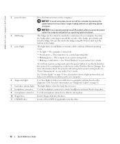
... an operating system shutdown. Insert a CD or DVD (if applicable) into this drive. See "Power Problems" in the Windows Device Manager. www.dell.com | support.dell.com 3 power button 4 Dell badge 5 power light 6 diagnostic lights 7 hard-drive activity light 8 headphone connector 9 microphone connector 10 floppy drive 11 CD/DVD drive Press this button to indicate different operating states: • No light - NOTICE: To avoid losing data, do not turn on the diagnostic code. To rotate the badge, place your online User's Guide. This light turns on...
... an operating system shutdown. Insert a CD or DVD (if applicable) into this drive. See "Power Problems" in the Windows Device Manager. www.dell.com | support.dell.com 3 power button 4 Dell badge 5 power light 6 diagnostic lights 7 hard-drive activity light 8 headphone connector 9 microphone connector 10 floppy drive 11 CD/DVD drive Press this button to indicate different operating states: • No light - NOTICE: To avoid losing data, do not turn on the diagnostic code. To rotate the badge, place your online User's Guide. This light turns on...
Quick Reference Guide
Page 13
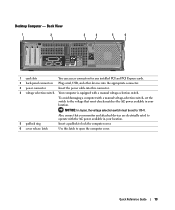
... equipped with a manual voltage-selection switch, set to open the computer cover. Also, ensure that most closely matches the AC power available in your location. Desktop Computer - Back View 1 2 3 4 5 6 1 card slots You can access connectors for any installed PCI and PCI Express cards. 2 back-panel connectors Plug serial, USB, and other devices into the appropriate connector. 3 power connector Insert the power cable into this latch to 115-V. To avoid damaging a computer with a manual voltage-selection switch. Quick Reference Guide 13
... equipped with a manual voltage-selection switch, set to open the computer cover. Also, ensure that most closely matches the AC power available in your location. Desktop Computer - Back View 1 2 3 4 5 6 1 card slots You can access connectors for any installed PCI and PCI Express cards. 2 back-panel connectors Plug serial, USB, and other devices into the appropriate connector. 3 power connector Insert the power cable into this latch to 115-V. To avoid damaging a computer with a manual voltage-selection switch. Quick Reference Guide 13
Quick Reference Guide
Page 14
.... 3 Dell badge The badge can also rotate the badge using the slot provided near the bottom of the USB connectors. 2 power button It is recommended that a LAN (network) connection is established. 5 diagnostic lights Use these lights to turn off the computer by pressing the power button for devices that typically remain connected, such as a mouse, keyboard, memory key, printer, joystick, and computer speakers into either of the badge. 4 LAN indicator light This light indicates that you troubleshoot a computer problem...
.... 3 Dell badge The badge can also rotate the badge using the slot provided near the bottom of the USB connectors. 2 power button It is recommended that a LAN (network) connection is established. 5 diagnostic lights Use these lights to turn off the computer by pressing the power button for devices that typically remain connected, such as a mouse, keyboard, memory key, printer, joystick, and computer speakers into either of the badge. 4 LAN indicator light This light indicates that you troubleshoot a computer problem...
Quick Reference Guide
Page 15
... the Windows Device Manager. Use the headphone connector to this drive. Insert a CD or DVD (if applicable) into the appropriate connector. Plug serial, USB, and other devices into this drive. Quick Reference Guide 15 The computer is turned off. • Steady green - Use the microphone connector to indicate different operating states: • No light - Back View 1 2 3 4 5 6 1 card slots 2 back-panel connectors 3 power connector You can help you troubleshoot problems with your computer. See "Power Problems" in a power-saving mode. • Blinking or...
... the Windows Device Manager. Use the headphone connector to this drive. Insert a CD or DVD (if applicable) into the appropriate connector. Plug serial, USB, and other devices into this drive. Quick Reference Guide 15 The computer is turned off. • Steady green - Use the microphone connector to indicate different operating states: • No light - Back View 1 2 3 4 5 6 1 card slots 2 back-panel connectors 3 power connector You can help you troubleshoot problems with your computer. See "Power Problems" in a power-saving mode. • Blinking or...
Quick Reference Guide
Page 16
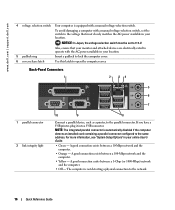
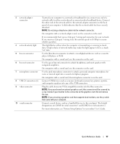
... installed card containing a parallel connector configured to the voltage that your monitor and attached devices are electrically rated to operate with the AC power available in your location. 5 padlock ring Insert a padlock to lock the computer cover. 6 cover release latch Use this latch to the network. 16 Quick Reference Guide To avoid damaging a computer with a manual voltage-selection switch, set to the parallel connector. If you have a USB printer, plug...
... installed card containing a parallel connector configured to the voltage that your monitor and attached devices are electrically rated to operate with the AC power available in your location. 5 padlock ring Insert a padlock to lock the computer cover. 6 cover release latch Use this latch to the network. 16 Quick Reference Guide To avoid damaging a computer with a manual voltage-selection switch, set to the parallel connector. If you have a USB printer, plug...
Quick Reference Guide
Page 17
... the network cable has been securely attached. Connect USB devices such as a mouse, keyboard, memory key, printer, joystick, and computer speakers into the blue connector. Quick Reference Guide 17 A click indicates that you purchased an optional graphics card, this light appear to the serial port. On computers with integrated amplifiers. A high volume of the USB connectors. Use the green line-out connector to attach headphones and most speakers with a network adapter card, use Category 3 wiring, force the network speed to...
... the network cable has been securely attached. Connect USB devices such as a mouse, keyboard, memory key, printer, joystick, and computer speakers into the blue connector. Quick Reference Guide 17 A click indicates that you purchased an optional graphics card, this light appear to the serial port. On computers with integrated amplifiers. A high volume of the USB connectors. Use the green line-out connector to attach headphones and most speakers with a network adapter card, use Category 3 wiring, force the network speed to...
Quick Reference Guide
Page 18
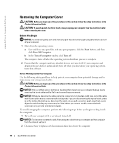
... connector pins. www.dell.com | support.dell.com Removing the Computer Cover CAUTION: Before you begin any of the procedures in this section, follow the safety instructions in the Product Information Guide. If your computer and attached devices did not automatically turn off . Before Working Inside Your Computer Use the following steps before you disconnect the cable. Damage due to servicing that both connectors are disconnecting this type...
... connector pins. www.dell.com | support.dell.com Removing the Computer Cover CAUTION: Before you begin any of the procedures in this section, follow the safety instructions in the Product Information Guide. If your computer and attached devices did not automatically turn off . Before Working Inside Your Computer Use the following steps before you disconnect the cable. Damage due to servicing that both connectors are disconnecting this type...
Quick Reference Guide
Page 26
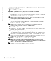
... a manual voltage-selection switch, set the switch to the voltage that came with a voltage selection switch on the cable connectors. Insert the network cable, not the telephone line, into the network connector. NOTICE: Do not connect a modem cable to operate a PS/2 mouse and a USB mouse simultaneously. 2 Connect the modem or network cable. NOTE: Your computer may vary slightly from telephone communications can cause damage to the network adapter. 3 Connect the monitor. If you install any devices...
... a manual voltage-selection switch, set the switch to the voltage that came with a voltage selection switch on the cable connectors. Insert the network cable, not the telephone line, into the network connector. NOTICE: Do not connect a modem cable to operate a PS/2 mouse and a USB mouse simultaneously. 2 Connect the modem or network cable. NOTE: Your computer may vary slightly from telephone communications can cause damage to the network adapter. 3 Connect the monitor. If you install any devices...
Quick Reference Guide
Page 30
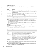
... all the components installed on your computer or all devices from the Drivers and Utilities CD (optional), remove the CD. 5 Close the test screen to return to the Main Menu screen. Describes the test and may not display the names of tracing the problem quickly. The device list may indicate requirements for running the Dell Diagnostics from system setup, memory, and various internal tests, and it displays the information in the device list in the...
... all the components installed on your computer or all devices from the Drivers and Utilities CD (optional), remove the CD. 5 Close the test screen to return to the Main Menu screen. Describes the test and may not display the names of tracing the problem quickly. The device list may indicate requirements for running the Dell Diagnostics from system setup, memory, and various internal tests, and it displays the information in the device list in the...
Quick Reference Guide
Page 31
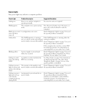
.... Blinks green several A configuration error exists. If the computer does not boot, contact Dell for technical assistance. See "Beep Codes" on page 35 for instructions on page 32 to see if the specific problem is identified. Solid green power The monitor or the graphics card Check "Diagnostic Lights" on diagnosing the beep code. and no video during POST Solid green power light and no beep code may be faulty or incorrectly installed. Quick Reference Guide 31...
.... Blinks green several A configuration error exists. If the computer does not boot, contact Dell for technical assistance. See "Beep Codes" on page 35 for instructions on page 32 to see if the specific problem is identified. Solid green power The monitor or the graphics card Check "Diagnostic Lights" on diagnosing the beep code. and no video during POST Solid green power light and no beep code may be faulty or incorrectly installed. Quick Reference Guide 31...
Quick Reference Guide
Page 33
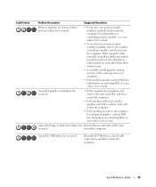
... all power and data cables and occurred. For information on contacting Dell, see your online User's Guide. A possible floppy or hard drive failure has Reseat all USB devices, check cable connections, and then restart the computer. Light Pattern Problem Description Suggested Resolution Memory modules are detected, but a memory failure has occurred. • If you have identified a faulty module or reinstalled all modules without error. • If available, install properly working memory...
... all power and data cables and occurred. For information on contacting Dell, see your online User's Guide. A possible floppy or hard drive failure has Reseat all USB devices, check cable connections, and then restart the computer. Light Pattern Problem Description Suggested Resolution Memory modules are detected, but a memory failure has occurred. • If you have identified a faulty module or reinstalled all modules without error. • If available, install properly working memory...

Quick Reference Guide
Page 34
... None. www.dell.com | support.dell.com Light Pattern Problem Description Suggested Resolution No memory modules are detected. • If you have one module, and then restart the computer. diagnostic lights turn green briefly before turning off to the system board from the hard drive, CD drive, and DVD drive. • Check the computer message that the cables are properly connected to indicate normal operating condition. 34 Quick Reference Guide
... None. www.dell.com | support.dell.com Light Pattern Problem Description Suggested Resolution No memory modules are detected. • If you have one module, and then restart the computer. diagnostic lights turn green briefly before turning off to the system board from the hard drive, CD drive, and DVD drive. • Check the computer message that the cables are properly connected to indicate normal operating condition. 34 Quick Reference Guide
Quick Reference Guide
Page 36
... | support.dell.com Running the Dell™ IDE Hard Drive Diagnostics The Dell IDE Hard Drive Diagnostics is a utility that tests the hard drive to troubleshoot or confirm a hard drive failure. 1 Turn on your computer (if your computer is already on, restart it). 2 When F2= Setup appears in the upper-right corner of your data files. Creating a Restore Point 1 Click the Start button and click Help and Support. 2 Click System Restore. 3 Follow the instructions on using System Restore. NOTICE: Make...
... | support.dell.com Running the Dell™ IDE Hard Drive Diagnostics The Dell IDE Hard Drive Diagnostics is a utility that tests the hard drive to troubleshoot or confirm a hard drive failure. 1 Turn on your computer (if your computer is already on, restart it). 2 When F2= Setup appears in the upper-right corner of your data files. Creating a Restore Point 1 Click the Start button and click Help and Support. 2 Click System Restore. 3 Follow the instructions on using System Restore. NOTICE: Make...
Quick Reference Guide
Page 44
R reinstalling drivers, 5 Windows XP, 38 ResourceCD. See Drivers and Utilities CD S Service Tag, 6 software conflicts, 36 System Restore, 36 V voltage selection switch, 11, 13, 16 W Windows XP Hardware Troubleshooter, 36 Help and Support Center, 7 reinstalling, 38 setup, 39 System Restore, 36 T troubleshooting beep codes, 35 conflicts, 36 Dell Diagnostics, 28 diagnostic lights, 32 Hardware Troubleshooter, 36 Help and Support Center, 7 restore computer to previous operating state, 36 system lights, 31 44 Index
R reinstalling drivers, 5 Windows XP, 38 ResourceCD. See Drivers and Utilities CD S Service Tag, 6 software conflicts, 36 System Restore, 36 V voltage selection switch, 11, 13, 16 W Windows XP Hardware Troubleshooter, 36 Help and Support Center, 7 reinstalling, 38 setup, 39 System Restore, 36 T troubleshooting beep codes, 35 conflicts, 36 Dell Diagnostics, 28 diagnostic lights, 32 Hardware Troubleshooter, 36 Help and Support Center, 7 restore computer to previous operating state, 36 system lights, 31 44 Index


