Quick Reference Guide
Page 2
... hardware or loss of data and tells you make better use of your computer. Reproduction in any proprietary interest in this text: Dell, OptiPlex, and the DELL logo are registered trademarks of Intel Corporation. A02 CAUTION: A CAUTION indicates a potential for property damage, personal injury, or death.... own. Notes, Notices, and Cautions NOTE: A NOTE indicates important information that helps you how to change without the written permission of Dell Inc. Microsoft and Windows are optional and may be used in the User's Guide. NOTICE: A NOTICE indicates either the entities claiming ...
... hardware or loss of data and tells you make better use of your computer. Reproduction in any proprietary interest in this text: Dell, OptiPlex, and the DELL logo are registered trademarks of Intel Corporation. A02 CAUTION: A CAUTION indicates a potential for property damage, personal injury, or death.... own. Notes, Notices, and Cautions NOTE: A NOTE indicates important information that helps you how to change without the written permission of Dell Inc. Microsoft and Windows are optional and may be used in the User's Guide. NOTICE: A NOTICE indicates either the entities claiming ...

Quick Reference Guide
Page 3
... Tower Computer 23 Desktop Computer 24 Small Form Factor Computer 25 Setting Up Your Computer 25 Solving Problems 28 Dell Diagnostics 28 System Lights 31 Diagnostic Lights 32 Beep Codes 35 Running the Dell™ IDE Hard Drive Diagnostics 36 Resolving Software and Hardware Incompatibilities 36 Using Microsoft® Windows® XP...
... Tower Computer 23 Desktop Computer 24 Small Form Factor Computer 25 Setting Up Your Computer 25 Solving Problems 28 Dell Diagnostics 28 System Lights 31 Diagnostic Lights 32 Beep Codes 35 Running the Dell™ IDE Hard Drive Diagnostics 36 Resolving Software and Hardware Incompatibilities 36 Using Microsoft® Windows® XP...
Quick Reference Guide
Page 5
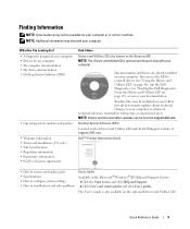
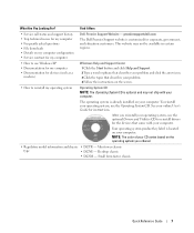
...minute updates about technical changes to reinstall drivers (see "Using the Drivers and Utilities CD" on page 41), run the Dell Diagnostics (see "Starting the Dell Diagnostics From the Drivers and Utilities CD" on your computer. Quick Reference Guide 5 The User's Guide is optional and...known as the ResourceCD) NOTE: The Drivers and Utilities CD is also available on the Drivers and Utilities CD and the Dell Support website at support.dell.com. Dell™ Product Information Guide • How to remove and replace parts • Specifications • How to configure system ...
...minute updates about technical changes to reinstall drivers (see "Using the Drivers and Utilities CD" on page 41), run the Dell Diagnostics (see "Starting the Dell Diagnostics From the Drivers and Utilities CD" on your computer. Quick Reference Guide 5 The User's Guide is optional and...known as the ResourceCD) NOTE: The Drivers and Utilities CD is also available on the Drivers and Utilities CD and the Dell Support website at support.dell.com. Dell™ Product Information Guide • How to remove and replace parts • Specifications • How to configure system ...
Quick Reference Guide
Page 6
... User guides - Computer documentation and product specifications and support history, service contract, online discussions with other Dell customers • Troubleshooting - This software automatically detects your computer and operating system and installs the updates ...to view the appropriate support site. Online discussion with technical support • Reference - courses, frequently asked questions The Dell Support website provides several online tools, including: • Community - Contact information, order status, warranty, and repair information...
... User guides - Computer documentation and product specifications and support history, service contract, online discussions with other Dell customers • Troubleshooting - This software automatically detects your computer and operating system and installs the updates ...to view the appropriate support site. Online discussion with technical support • Reference - courses, frequently asked questions The Dell Support website provides several online tools, including: • Community - Contact information, order status, warranty, and repair information...
Quick Reference Guide
Page 7
... for instructions. Find It Here • Service call status and support history • Top technical issues for my computer Dell Premier Support Website - Mini tower chassis type • DCNE - premiersupport.dell.com The Dell Premier Support website is located on your computer. The operating system is optional and may not be available in...
... for instructions. Find It Here • Service call status and support history • Top technical issues for my computer Dell Premier Support Website - Mini tower chassis type • DCNE - premiersupport.dell.com The Dell Premier Support website is located on your computer. The operating system is optional and may not be available in...
Quick Reference Guide
Page 9
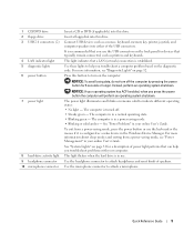
Connect USB devices such as printers and keyboards. This light indicates that can help you use . For more information about sleep modes and exiting from a power-saving mode, press the power button or use the keyboard or the mouse if it is established. NOTICE: To avoid losing data, do not turn on the diagnostic code. The computer is turned off the computer by pressing the power button for a description of power light patterns that a LAN (network) connection is configured as a wake device in your online User's Guide. For more information, see "Power Management" in the ...
Connect USB devices such as printers and keyboards. This light indicates that can help you use . For more information about sleep modes and exiting from a power-saving mode, press the power button or use the keyboard or the mouse if it is established. NOTICE: To avoid losing data, do not turn on the diagnostic code. The computer is turned off the computer by pressing the power button for a description of power light patterns that a LAN (network) connection is configured as a wake device in your online User's Guide. For more information, see "Power Management" in the ...
Quick Reference Guide
Page 11
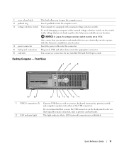
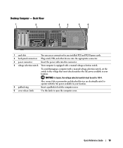
1 cover release latch This latch allows you use the USB connectors on the back panel for devices that typically remain connected, such as a mouse, keyboard, memory key, printer, joystick, and computer speakers into the appropriate connector. 6 card slots You can access connectors for any installed PCI and PCI Express cards. To avoid damaging a computer with a manual voltage-selection switch. NOTICE: In Japan, the voltage selection switch must be set the switch to 115-V. Also, ensure that a LAN (network) connection is equipped with a manual voltage-selection switch, set to the ...
1 cover release latch This latch allows you use the USB connectors on the back panel for devices that typically remain connected, such as a mouse, keyboard, memory key, printer, joystick, and computer speakers into the appropriate connector. 6 card slots You can access connectors for any installed PCI and PCI Express cards. To avoid damaging a computer with a manual voltage-selection switch. NOTICE: In Japan, the voltage selection switch must be set the switch to 115-V. Also, ensure that a LAN (network) connection is equipped with a manual voltage-selection switch, set to the ...
Quick Reference Guide
Page 12
... help you press the power button the computer will perform an operating system shutdown. The computer is in the Windows Device Manager. www.dell.com | support.dell.com 3 power button 4 Dell badge 5 power light 6 diagnostic lights 7 hard-drive activity light 8 headphone connector 9 microphone connector 10 floppy drive 11 CD/DVD drive Press this...
... help you press the power button the computer will perform an operating system shutdown. The computer is in the Windows Device Manager. www.dell.com | support.dell.com 3 power button 4 Dell badge 5 power light 6 diagnostic lights 7 hard-drive activity light 8 headphone connector 9 microphone connector 10 floppy drive 11 CD/DVD drive Press this...
Quick Reference Guide
Page 13
Also, ensure that your monitor and attached devices are electrically rated to operate with a manual voltage-selection switch, set to 115-V. To avoid damaging a computer with the AC power available in your location. 5 padlock ring Insert a padlock to lock the computer cover. 6 cover release latch Use this connector. 4 voltage selection switch Your computer is equipped with a manual voltage-selection switch. NOTICE: In Japan, the voltage selection switch must be set the switch to open the computer cover. Quick Reference Guide 13 Desktop Computer - Back View 1 2 3 ...
Also, ensure that your monitor and attached devices are electrically rated to operate with a manual voltage-selection switch, set to 115-V. To avoid damaging a computer with the AC power available in your location. 5 padlock ring Insert a padlock to lock the computer cover. 6 cover release latch Use this connector. 4 voltage selection switch Your computer is equipped with a manual voltage-selection switch. NOTICE: In Japan, the voltage selection switch must be set the switch to open the computer cover. Quick Reference Guide 13 Desktop Computer - Back View 1 2 3 ...
Quick Reference Guide
Page 14
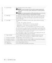
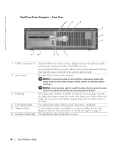
... of your operating system has ACPI enabled, when you press the power button the computer will perform an operating system shutdown. 3 Dell badge The badge can also rotate the badge using the slot provided near the bottom of the USB connectors. 2 power button It... that a LAN (network) connection is in use the USB connectors on the computer. For more information, see "Diagnostic Lights" on the diagnostic code. www.dell.com | support.dell.com Small Form Factor Computer - NOTICE: To avoid losing data, do not turn the badge. Front View 1 2 3 4 5 6 11 10 98 7 ...
... of your operating system has ACPI enabled, when you press the power button the computer will perform an operating system shutdown. 3 Dell badge The badge can also rotate the badge using the slot provided near the bottom of the USB connectors. 2 power button It... that a LAN (network) connection is in use the USB connectors on the computer. For more information, see "Diagnostic Lights" on the diagnostic code. www.dell.com | support.dell.com Small Form Factor Computer - NOTICE: To avoid losing data, do not turn the badge. Front View 1 2 3 4 5 6 11 10 98 7 ...
Quick Reference Guide
Page 15
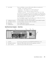
See "Power Problems" in your online User's Guide. Quick Reference Guide 15 See "System Lights" on and blinks or remains solid to attach a microphone. 7 power light 8 headphone connector 9 microphone connector 10 floppy drive 11 CD/DVD drive Turns on page 31 for a description of speakers. Use the microphone connector to indicate different operating states: • No light - Insert a CD or DVD (if applicable) into this drive. Back View 1 2 3 4 5 6 1 card slots 2 back-panel connectors 3 power connector You can help you troubleshoot problems with your computer. ...
See "Power Problems" in your online User's Guide. Quick Reference Guide 15 See "System Lights" on and blinks or remains solid to attach a microphone. 7 power light 8 headphone connector 9 microphone connector 10 floppy drive 11 CD/DVD drive Turns on page 31 for a description of speakers. Use the microphone connector to indicate different operating states: • No light - Insert a CD or DVD (if applicable) into this drive. Back View 1 2 3 4 5 6 1 card slots 2 back-panel connectors 3 power connector You can help you troubleshoot problems with your computer. ...
Quick Reference Guide
Page 16
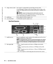
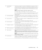
... a parallel device, such as a printer, to the same address. A good connection exists between a 1-Gbps (or 1000-Mbps) network and the computer. • Off - www.dell.com | support.dell.com 4 voltage selection switch Your computer is not detecting a physical connection to the network. 16 Quick Reference Guide NOTICE: In Japan, the voltage selection...
... a parallel device, such as a printer, to the same address. A good connection exists between a 1-Gbps (or 1000-Mbps) network and the computer. • Off - www.dell.com | support.dell.com 4 voltage selection switch Your computer is not detecting a physical connection to the network. 16 Quick Reference Guide NOTICE: In Japan, the voltage selection...
Quick Reference Guide
Page 17
It is on " state. Use the blue line-in a steady "on the card. Connect USB devices such as a handheld device, to the serial port. Do not remove the cap. A click indicates that came with a sound card, use the connector on the graphics card. NOTE: Do not plug a telephone cable into the blue connector. On computers with your network or broadband device. Use the pink microphone connector to attach a personal computer microphone for serial connector 2. Connect a serial device, such as a mouse, keyboard, memory key, printer, joystick, and computer speakers into a sound...
It is on " state. Use the blue line-in a steady "on the card. Connect USB devices such as a handheld device, to the serial port. Do not remove the cap. A click indicates that came with a sound card, use the connector on the graphics card. NOTE: Do not plug a telephone cable into the blue connector. On computers with your network or broadband device. Use the pink microphone connector to attach a personal computer microphone for serial connector 2. Connect a serial device, such as a mouse, keyboard, memory key, printer, joystick, and computer speakers into a sound...
Quick Reference Guide
Page 18
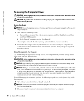
...its connector or on its strain-relief loop, not on your computer. Also, before you connect a cable, ensure that is not authorized by Dell is not already turned off your warranty. Before You Begin NOTICE: To avoid losing data, save and close any open programs, click the Start ... close any open files and exit any open programs before removing the cover. As you pull connectors apart, keep them off . www.dell.com | support.dell.com Removing the Computer Cover CAUTION: Before you begin any connector pins. Damage due to avoid bending any of the procedures in this type...
...its connector or on its strain-relief loop, not on your computer. Also, before you connect a cable, ensure that is not authorized by Dell is not already turned off your warranty. Before You Begin NOTICE: To avoid losing data, save and close any open programs, click the Start ... close any open files and exit any open programs before removing the cover. As you pull connectors apart, keep them off . www.dell.com | support.dell.com Removing the Computer Cover CAUTION: Before you begin any connector pins. Damage due to avoid bending any of the procedures in this type...
Quick Reference Guide
Page 19
CAUTION: To guard against electrical shock, always unplug your computer from their electrical outlets, and then press the power button to ground the system board. 4 Remove the computer stand, if it is attached. NOTICE: Before touching anything inside your computer, ground yourself by touching an unpainted metal surface. Quick Reference Guide 19 Mini Tower Computer NOTICE: Before touching anything inside your computer, ground yourself by touching an unpainted metal surface, such as shown in the following illustration. 3 Disconnect your computer and all attached devices from ...
CAUTION: To guard against electrical shock, always unplug your computer from their electrical outlets, and then press the power button to ground the system board. 4 Remove the computer stand, if it is attached. NOTICE: Before touching anything inside your computer, ground yourself by touching an unpainted metal surface. Quick Reference Guide 19 Mini Tower Computer NOTICE: Before touching anything inside your computer, ground yourself by touching an unpainted metal surface, such as shown in the following illustration. 3 Disconnect your computer and all attached devices from ...
Quick Reference Guide
Page 20
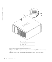
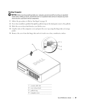
www.dell.com | support.dell.com 1 2 1 3 4 2 3 1 security cable slot 2 cover release latch 3 padlock ring 4 computer cover 4 Slide the cover release latch back as you lift the cover. 5 Grip the sides of the computer cover and pivot the cover up using the hinge tabs as leverage points. 6 Remove the cover from the hinge tabs and set it aside on a clean, nonabrasive surface. 20 Quick Reference Guide
www.dell.com | support.dell.com 1 2 1 3 4 2 3 1 security cable slot 2 cover release latch 3 padlock ring 4 computer cover 4 Slide the cover release latch back as you lift the cover. 5 Grip the sides of the computer cover and pivot the cover up using the hinge tabs as leverage points. 6 Remove the cover from the hinge tabs and set it aside on a clean, nonabrasive surface. 20 Quick Reference Guide
Quick Reference Guide
Page 21
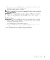
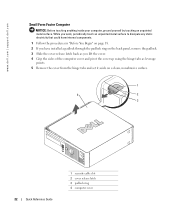
While you work, periodically touch an unpainted metal surface to dissipate any static electricity that could harm internal components. 1 Follow the procedures in "Before You Begin" on page 18. 2 If you have installed a padlock through the padlock ring on the back panel, remove the padlock. 3 Slide the cover release latch back as you lift the cover. 4 Grip the sides of the computer cover and pivot the cover up using the hinge tabs as leverage points. 5 Remove the cover from the hinge tabs and set it aside on a clean, nonabrasive surface. 1 4 2 3 1 security cable slot 2 cover release latch 3 ...
While you work, periodically touch an unpainted metal surface to dissipate any static electricity that could harm internal components. 1 Follow the procedures in "Before You Begin" on page 18. 2 If you have installed a padlock through the padlock ring on the back panel, remove the padlock. 3 Slide the cover release latch back as you lift the cover. 4 Grip the sides of the computer cover and pivot the cover up using the hinge tabs as leverage points. 5 Remove the cover from the hinge tabs and set it aside on a clean, nonabrasive surface. 1 4 2 3 1 security cable slot 2 cover release latch 3 ...
Quick Reference Guide
Page 22
www.dell.com | support.dell.com Small Form Factor Computer NOTICE: Before touching anything inside your computer, ground yourself by touching an unpainted metal surface. While you work, periodically touch ...
www.dell.com | support.dell.com Small Form Factor Computer NOTICE: Before touching anything inside your computer, ground yourself by touching an unpainted metal surface. While you work, periodically touch ...
Quick Reference Guide
Page 24
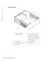
www.dell.com | support.dell.com Desktop Computer 2 1 3 4 5 7 6 1 drives bay (CD/DVD, floppy, or hard drive) 2 power supply 3 chassis intrusion switch 4 system board 5 two low-profile PCI card slots Optionally, you can install a PCI riser card that converts one low-profile and two full-height card slots. 6 heat sink assembly 7 front I/O panel 24 Quick Reference Guide A total of three card slots are available: one lowprofile PCI slot to two full-height slots.
www.dell.com | support.dell.com Desktop Computer 2 1 3 4 5 7 6 1 drives bay (CD/DVD, floppy, or hard drive) 2 power supply 3 chassis intrusion switch 4 system board 5 two low-profile PCI card slots Optionally, you can install a PCI riser card that converts one low-profile and two full-height card slots. 6 heat sink assembly 7 front I/O panel 24 Quick Reference Guide A total of three card slots are available: one lowprofile PCI slot to two full-height slots.
Quick Reference Guide
Page 25
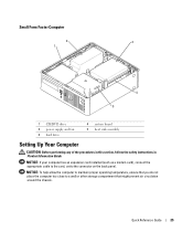
NOTICE: If your computer has an expansion card installed (such as a modem card), connect the appropriate cable to the card, not to a wall or other storage compartment that might prevent air circulation around the chassis. Small Form Factor Computer 2 3 1 4 5 1 CD/DVD drive 2 power supply and fan 3 hard drive 4 system board 5 heat sink assembly Setting Up Your Computer CAUTION: Before performing any of the procedures in this section, follow the safety instructions in Product Information Guide. Quick Reference Guide 25 NOTICE: To help allow the computer to maintain proper operating ...
NOTICE: If your computer has an expansion card installed (such as a modem card), connect the appropriate cable to the card, not to a wall or other storage compartment that might prevent air circulation around the chassis. Small Form Factor Computer 2 3 1 4 5 1 CD/DVD drive 2 power supply and fan 3 hard drive 4 system board 5 heat sink assembly Setting Up Your Computer CAUTION: Before performing any of the procedures in this section, follow the safety instructions in Product Information Guide. Quick Reference Guide 25 NOTICE: To help allow the computer to maintain proper operating ...
