
User Guide
Page 3
... Computing Habits 11 1 About Your Computer Front View 16 Front Panel Door 19 Speaker/Headphone Connector 20 Power Button 20 Power Light 22 Floppy Drive Access Light 23 Hard Drive Access Light 23 Back View 23 Connecting Devices 26 Parallel Connector 27 Mouse Connector 27 USB Connectors 27 Integrated Network Adapter Connector 27 Network Cable Requirements 27 Line-In Jack 28 Line-Out Jack 28 Microphone Jack 28 Serial Port Connectors 28 Keyboard Connector 28 Video Connector 28 Inside Your Computer 29 Contents iii
... Computing Habits 11 1 About Your Computer Front View 16 Front Panel Door 19 Speaker/Headphone Connector 20 Power Button 20 Power Light 22 Floppy Drive Access Light 23 Hard Drive Access Light 23 Back View 23 Connecting Devices 26 Parallel Connector 27 Mouse Connector 27 USB Connectors 27 Integrated Network Adapter Connector 27 Network Cable Requirements 27 Line-In Jack 28 Line-Out Jack 28 Microphone Jack 28 Serial Port Connectors 28 Keyboard Connector 28 Video Connector 28 Inside Your Computer 29 Contents iii
User Guide
Page 4
... Technology Control 40 Manageability 40 Dell OpenManage IT Assistant 40 Dell OpenManage Client Instrumentation 41 Security 41 Chassis Intrusion Detection 41 Security Cable Slot and Padlock Ring 42 Password Protection 42 System Password 42 Setup Password 45 Disabling a Forgotten Password 46 Computer Settings 47 Entering System Setup 48 System Setup Screens 48 Changing the Boot Sequence 50 Additional System Setup Options 52 If You Have a Problem 58 Jumper Settings 58 Software Installation and Configuration 60 3 Installing Upgrades Opening the Computer Cover...
... Technology Control 40 Manageability 40 Dell OpenManage IT Assistant 40 Dell OpenManage Client Instrumentation 41 Security 41 Chassis Intrusion Detection 41 Security Cable Slot and Padlock Ring 42 Password Protection 42 System Password 42 Setup Password 45 Disabling a Forgotten Password 46 Computer Settings 47 Entering System Setup 48 System Setup Screens 48 Changing the Boot Sequence 50 Additional System Setup Options 52 If You Have a Problem 58 Jumper Settings 58 Software Installation and Configuration 60 3 Installing Upgrades Opening the Computer Cover...
User Guide
Page 5
... Removing the Expansion-Card Cage 74 Replacing the Expansion-Card Cage 75 Memory 76 Installing DIMMs 77 Removing DIMMs 79 Microprocessor 80 Front Panel Inserts 85 Removing Front Panel Inserts-Small Form-Factor and Small Desktop Computers 85 Removing Front Panel Inserts-Small Mini-Tower Computer . . 88 Replacing Front Panel Inserts 89 Internal Drives 89 IDE Drive Addressing 92 Connecting Drives 93 Hard Drives 95 Detaching Hard Drive Cables 96 Removing a Hard Drive 99 Installing a Hard Drive 102 Reattaching Hard Drive Cables 103 Adding a Second Hard Drive...
... Removing the Expansion-Card Cage 74 Replacing the Expansion-Card Cage 75 Memory 76 Installing DIMMs 77 Removing DIMMs 79 Microprocessor 80 Front Panel Inserts 85 Removing Front Panel Inserts-Small Form-Factor and Small Desktop Computers 85 Removing Front Panel Inserts-Small Mini-Tower Computer . . 88 Replacing Front Panel Inserts 89 Internal Drives 89 IDE Drive Addressing 92 Connecting Drives 93 Hard Drives 95 Detaching Hard Drive Cables 96 Removing a Hard Drive 99 Installing a Hard Drive 102 Reattaching Hard Drive Cables 103 Adding a Second Hard Drive...
User Guide
Page 16
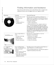
... the operating system setup. • Product Key (also called the Product ID or Certificate of your Dell™ computer. • Express Service Code and Service Tag Number The Express Service Code and Service Tag Number are already installed on your computer's boot sequence (see Changing the Boot Sequence). Contents Dell OptiPlex ResourceCD • Dell Diagnostics • Drivers • Utilities • Computer and device documentation Setup and Quick Reference Guide • Getting started/setup • Support tools • Solving Problems...
... the operating system setup. • Product Key (also called the Product ID or Certificate of your Dell™ computer. • Express Service Code and Service Tag Number The Express Service Code and Service Tag Number are already installed on your computer's boot sequence (see Changing the Boot Sequence). Contents Dell OptiPlex ResourceCD • Dell Diagnostics • Drivers • Utilities • Computer and device documentation Setup and Quick Reference Guide • Getting started/setup • Support tools • Solving Problems...

User Guide
Page 17
... Resource Operating system CD Use the operating system CD, which was shipped with your computer, to access the electronic documentation stored on selected operating systems) • Getting technical assistance Abo u t Yo u r C o m p u te r 15 Obtain information on the following: • Using your computer • Configuring system settings • Removing and installing parts • Installing and configuring software • Diagnosing a problem • Obtaining technical specifications • Acquiring device documentation (on your hard drive.
... Resource Operating system CD Use the operating system CD, which was shipped with your computer, to access the electronic documentation stored on selected operating systems) • Getting technical assistance Abo u t Yo u r C o m p u te r 15 Obtain information on the following: • Using your computer • Configuring system settings • Removing and installing parts • Installing and configuring software • Diagnosing a problem • Obtaining technical specifications • Acquiring device documentation (on your hard drive.
User Guide
Page 28
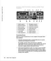
Fact or, Desktop, and Mini-Tower Computers 1 23 4 56 7 14 13 12 11 10 9 8 1 Parallel connector 2 Keyboard connector 3 Mouse connector 4 Link integrity light 5 Network adapter 6 Activity light 7 Video connector (1) 8 Microphone connector 9 Audio line-in connector 10 Audio line-out connector 11 USB connectors (2) 12 Diagnostic lights 13 Serial 2 connector 14 Serial 1 connector Connecting Devices When you to load device drivers into computer memory before turning on the computer.) 26 Abo u t You r C o mp u t er Also, external devices like a mouse or printer usually require you ...
Fact or, Desktop, and Mini-Tower Computers 1 23 4 56 7 14 13 12 11 10 9 8 1 Parallel connector 2 Keyboard connector 3 Mouse connector 4 Link integrity light 5 Network adapter 6 Activity light 7 Video connector (1) 8 Microphone connector 9 Audio line-in connector 10 Audio line-out connector 11 USB connectors (2) 12 Diagnostic lights 13 Serial 2 connector 14 Serial 1 connector Connecting Devices When you to load device drivers into computer memory before turning on the computer.) 26 Abo u t You r C o mp u t er Also, external devices like a mouse or printer usually require you ...
User Guide
Page 29
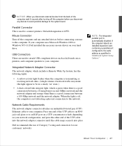
... system board. When the light is off, the computer is used to attach USB-compliant devices such as specified in a steady "on your hard drive. Parallel Connector This is not detecting a physical connection to the network. If your computer uses Microsoft Windows 2000 or Windows NT 4.0, Dell installed the necessary mouse drivers on your network configuration, and press the other end of the UTP cable into the network adapter connector until the cable snaps...
... system board. When the light is off, the computer is used to attach USB-compliant devices such as specified in a steady "on your hard drive. Parallel Connector This is not detecting a physical connection to the network. If your computer uses Microsoft Windows 2000 or Windows NT 4.0, Dell installed the necessary mouse drivers on your network configuration, and press the other end of the UTP cable into the network adapter connector until the cable snaps...
User Guide
Page 30
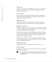
... attach computer speakers. Connect the audio cable from any of these devices to the line-in jack. Before you add an expansion card containing a serial port using this jack. Keyboard Connector Attach the keyboard cable to the 6-pin connector on the back panel. Serial Port Connectors Default port designations: COM1 for serial port 1 and COM2 for a secondary display if multi-monitor is used to attach a standard personal computer microphone. Video Connector This connector is used to attach record/playback devices such as...
... attach computer speakers. Connect the audio cable from any of these devices to the line-in jack. Before you add an expansion card containing a serial port using this jack. Keyboard Connector Attach the keyboard cable to the 6-pin connector on the back panel. Serial Port Connectors Default port designations: COM1 for serial port 1 and COM2 for a secondary display if multi-monitor is used to attach a standard personal computer microphone. Video Connector This connector is used to attach record/playback devices such as...
User Guide
Page 49
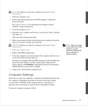
... and turn them on. CAUTION: Before you open the computer cover, see "Safety Instructions." 1 Open the computer cover. 2 Remove the jumper plug from the PSWD jumper to disable the password feature. Proceed to step 6 if you start your computer and devices to locate the password jumper (labeled "PSWD") on . Computer Settings Each time you want to reenable the password feature. If the computer detects a discrepancy, it compares the installed hardware with...
... and turn them on. CAUTION: Before you open the computer cover, see "Safety Instructions." 1 Open the computer cover. 2 Remove the jumper plug from the PSWD jumper to disable the password feature. Proceed to step 6 if you start your computer and devices to locate the password jumper (labeled "PSWD") on . Computer Settings Each time you want to reenable the password feature. If the computer detects a discrepancy, it compares the installed hardware with...
User Guide
Page 53
... press at the Dell logo screen during computer boot. MBA UNDI then appears under Boot Sequence only if the Network Interface Controller option is set to On or Off, set to boot from the next device in case you want to restore it will attempt to On w/MBA. and down-arrow keys to move through the list of devices. 3 Press the spacebar to enable or disable a device (enabled devices appear with...
... press at the Dell logo screen during computer boot. MBA UNDI then appears under Boot Sequence only if the Network Interface Controller option is set to On or Off, set to boot from the next device in case you want to restore it will attempt to On w/MBA. and down-arrow keys to move through the list of devices. 3 Press the spacebar to enable or disable a device (enabled devices appear with...
User Guide
Page 54
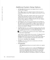
... power is restored. You can type numbers in both the date and time fields. www.dell.com | support.dell.com Additional System Setup Options • AC Power Recovery determines what happens when AC power is Disabled. • CPU ID provides the manufacturer's identification code for the installed microprocessor. • CPU Information - The default for Auto Power On is restored to turn on when AC power is lost, the computer starts up when AC power...
... power is restored. You can type numbers in both the date and time fields. www.dell.com | support.dell.com Additional System Setup Options • AC Power Recovery determines what happens when AC power is Disabled. • CPU ID provides the manufacturer's identification code for the installed microprocessor. • CPU Information - The default for Auto Power On is restored to turn on when AC power is lost, the computer starts up when AC power...
User Guide
Page 57
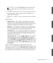
... to the type of device connected to the parallel port. Diskette Interface: controls the operation of the boot routine, the computer first checks for a primary hard drive controller card installed in an expansion slot. Press to accommodate a controller card installed in the following subsections. I/O Address: This option determines the I/O address used by the parallel port and appears except when Mode is turned off. The available options are running the Microsoft® Windows® 95...
... to the type of device connected to the parallel port. Diskette Interface: controls the operation of the boot routine, the computer first checks for a primary hard drive controller card installed in an expansion slot. Press to accommodate a controller card installed in the following subsections. I/O Address: This option determines the I/O address used by the parallel port and appears except when Mode is turned off. The available options are running the Microsoft® Windows® 95...
User Guide
Page 60
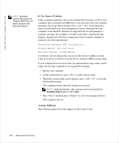
... your changes and exit. If your computer does not reset after you perform these steps, enter system setup and reset the computer to load the Dell default settings. Jumper Settings The following message: Performing automatic IDE configuration... Press in system setup. If no device is set the hard drive autoconfiguration feature. NOTE: Verify that the time, date, and year are restored. Primary Master: IDE Disk Drive Secondary Master: CD-ROM Reader...
... your changes and exit. If your computer does not reset after you perform these steps, enter system setup and reset the computer to load the Dell default settings. Jumper Settings The following message: Performing automatic IDE configuration... Press in system setup. If no device is set the hard drive autoconfiguration feature. NOTE: Verify that the time, date, and year are restored. Primary Master: IDE Disk Drive Secondary Master: CD-ROM Reader...
User Guide
Page 76
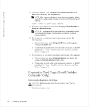
..., see "I /O Panel-Small Form-Factor, Desktop, and MiniTower Computers"). b Connect external audio devices to the audio connectors on the I/O panel (see "Safety Instructions." 1 Open the computer cover. 74 Instal ling Upgrades Expansion Card Cage (Small Desktop Computer Only) Removing the Expansion-Card Cage CAUTION: Before you removed an add-in network adapter, perform the following steps: a Enter system setup, select Integrated Devices, and change the setting for Sound to the integrated connector on the screen at the next computer start-up...
..., see "I /O Panel-Small Form-Factor, Desktop, and MiniTower Computers"). b Connect external audio devices to the audio connectors on the I/O panel (see "Safety Instructions." 1 Open the computer cover. 74 Instal ling Upgrades Expansion Card Cage (Small Desktop Computer Only) Removing the Expansion-Card Cage CAUTION: Before you removed an add-in network adapter, perform the following steps: a Enter system setup, select Integrated Devices, and change the setting for Sound to the integrated connector on the screen at the next computer start-up...
User Guide
Page 146
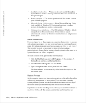
... the Start button, point to All Programs-> Accessories-> System Tools, and then click System Restore. 2 Select Create a restore point and click Next>. 3 Type a description of Windows detects unsigned device-driver installations. Restore Process As the computer is optimal. When you can use the System Restore feature to use System Restore. 144 Micros of the new restore point. Drivers that is unsuccessful, then use Driver Rollback. If you encounter operating system problems...
... the Start button, point to All Programs-> Accessories-> System Tools, and then click System Restore. 2 Select Create a restore point and click Next>. 3 Type a description of Windows detects unsigned device-driver installations. Restore Process As the computer is optimal. When you can use the System Restore feature to use System Restore. 144 Micros of the new restore point. Drivers that is unsuccessful, then use Driver Rollback. If you encounter operating system problems...
User Guide
Page 156
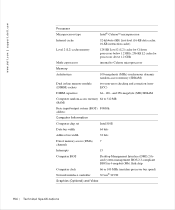
... address Computer Information Computer chip set Intel 810E Data bus width 64 bits Address bus width 32 bits Direct memory access (DMA) 7 channels Interrupts 15 Computer BIOS Desktop Management Interface (DMI) 2.0sand system management BIOS 2.3-compliant BIOS in 4-megabit (Mb) flash chip Computer clock Network interface controller 66 or 100 MHz (matches processor bus speed) 3Com® 3C920 Graphics (Optional) and Video 154 Te c h n ic a l Sp e c if...
... address Computer Information Computer chip set Intel 810E Data bus width 64 bits Address bus width 32 bits Direct memory access (DMA) 7 channels Interrupts 15 Computer BIOS Desktop Management Interface (DMI) 2.0sand system management BIOS 2.3-compliant BIOS in 4-megabit (Mb) flash chip Computer clock Network interface controller 66 or 100 MHz (matches processor bus speed) 3Com® 3C920 Graphics (Optional) and Video 154 Te c h n ic a l Sp e c if...
User Guide
Page 198
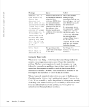
... Diagnostics Checklist found in nonvolatile random-access memory (NVRAM). Problems." Computer Beep Codes When errors occur during a boot routine that the computer was unable to resolve the problem, see "Getting Help" for instructions on a copy of sounds: for its operating specifications. Write fault Write fault on selected drive The operating system See "Floppy Drive cannot write to None. The beep code is not the only bootable drive, enter system setup and change...
... Diagnostics Checklist found in nonvolatile random-access memory (NVRAM). Problems." Computer Beep Codes When errors occur during a boot routine that the computer was unable to resolve the problem, see "Getting Help" for instructions on a copy of sounds: for its operating specifications. Write fault Write fault on selected drive The operating system See "Floppy Drive cannot write to None. The beep code is not the only bootable drive, enter system setup and change...
User Guide
Page 201
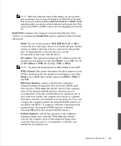
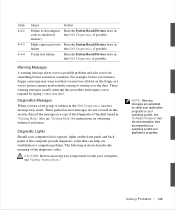
... this section. Diagnostics Messages When you troubleshoot a computer problem. These particular error messages are generated by typing y (yes) or n (no). Also see "Safety Instructions." Code 4-4-2 4-4-3 4-4-4 Cause Failure to decompress code to shadowed memory Math-coprocessor test failure Cache test failure Action Run the System Board Devices tests in the Dell Diagnostics if possible. Diagnostic Lights Should your operating system. See "Software Problems" and the documentation that can help you run a test group or subtest in the Dell Diagnostics, if...
... this section. Diagnostics Messages When you troubleshoot a computer problem. These particular error messages are generated by typing y (yes) or n (no). Also see "Safety Instructions." Code 4-4-2 4-4-3 4-4-4 Cause Failure to decompress code to shadowed memory Math-coprocessor test failure Cache test failure Action Run the System Board Devices tests in the Dell Diagnostics if possible. Diagnostic Lights Should your operating system. See "Software Problems" and the documentation that can help you run a test group or subtest in the Dell Diagnostics, if...

User Guide
Page 224
www.dell.com | support.dell.com Country (City) International Access Code Country Code City Code Jamaica Japan (Kawasaki) International Access Code: 001 Country Code: 81 City Code: 44 Korea (Seoul) International Access Code: 001 Country Code: 82 City Code: 2 Department Name or Service Area, Website and E-Mail Address General Support Technical Support (Server) Technical Support Outside of Japan (Server) Technical Support (Dimension™ and Inspiron™) Technical Support Outside of Japan (Dimension and Inspiron) Technical Support (Dell Precision™, OptiPlex™, and Latitude&#...
www.dell.com | support.dell.com Country (City) International Access Code Country Code City Code Jamaica Japan (Kawasaki) International Access Code: 001 Country Code: 81 City Code: 44 Korea (Seoul) International Access Code: 001 Country Code: 82 City Code: 2 Department Name or Service Area, Website and E-Mail Address General Support Technical Support (Server) Technical Support Outside of Japan (Server) Technical Support (Dimension™ and Inspiron™) Technical Support Outside of Japan (Dimension and Inspiron) Technical Support (Dell Precision™, OptiPlex™, and Latitude&#...
User Guide
Page 252
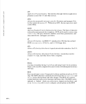
... must control IRQs. ASCII can be updated, or "flashed," which an application program accesses the OS and other drives with digital electronics and logic. ATAPI Advanced Technology Attachment Packet Interface. Composed of numbers having 2 as its notation. The BIOS can correct errors, support new hardware, and so on a ROM chip. Prioritizes and manages IRQs for its base and using 0 and 1 for the various devices in...
... must control IRQs. ASCII can be updated, or "flashed," which an application program accesses the OS and other drives with digital electronics and logic. ATAPI Advanced Technology Attachment Packet Interface. Composed of numbers having 2 as its notation. The BIOS can correct errors, support new hardware, and so on a ROM chip. Prioritizes and manages IRQs for its base and using 0 and 1 for the various devices in...


