
View
Page 1
...7. back panel connectors 14. Front And Back View Of Mini-Tower 1. power supply diagnostic light 11. drive activity light 10. power supply diagnostic button 12. optical-drive bay (optional) 3. diagnostic lights (4) 6. optical-drive eject button 8. power connector 13. expansion-card slots (4) 15. padlock... Type: D09M001, D05D001, D03S001, D01U002 2011 - 02 Front And Back View Figure 1. power button, power light 2. Mini-Tower - Dell OptiPlex 790 Setup And Features Information About Warnings WARNING: A WARNING indicates a potential for property damage, personal injury, or death.
...7. back panel connectors 14. Front And Back View Of Mini-Tower 1. power supply diagnostic light 11. drive activity light 10. power supply diagnostic button 12. optical-drive bay (optional) 3. diagnostic lights (4) 6. optical-drive eject button 8. power connector 13. expansion-card slots (4) 15. padlock... Type: D09M001, D05D001, D03S001, D01U002 2011 - 02 Front And Back View Figure 1. power button, power light 2. Mini-Tower - Dell OptiPlex 790 Setup And Features Information About Warnings WARNING: A WARNING indicates a potential for property damage, personal injury, or death.
View
Page 2
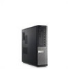
optical drive 2. USB 2.0 connectors (4) 5. security-cable slot 11. power supply diagnostic button 2 Front And Back View Figure 2. optical-drive eject button 3. power connector 12. headphone connector 7. drive activity light 8. padlock ring 10. power supply diagnostic light 15. microphone connector 6. Front And Back View Of Desktop 1. back panel connectors 13. expansion-card slots (4) 14. Desktop - power button, power light 4. diagnostic lights (4) 9.
optical drive 2. USB 2.0 connectors (4) 5. security-cable slot 11. power supply diagnostic button 2 Front And Back View Figure 2. optical-drive eject button 3. power connector 12. headphone connector 7. drive activity light 8. padlock ring 10. power supply diagnostic light 15. microphone connector 6. Front And Back View Of Desktop 1. back panel connectors 13. expansion-card slots (4) 14. Desktop - power button, power light 4. diagnostic lights (4) 9.
View
Page 3
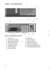
Small Form Factor - optical-drive eject button 3. power button, power light 4. headphone connector 7. security-cable slot 11. expansion-card slots (2) 3 Front And Back View Figure 3. optical drive 2. microphone connector 6. drive activity light 9. power connector 12. USB 2.0 connectors (4) 5. power supply diagnostic light 14. back panel connectors 15. Front And Back View Of Small Form Factor 1. diagnostic lights (4) 8. padlock ring 10. power supply diagnostic button 13.
Small Form Factor - optical-drive eject button 3. power button, power light 4. headphone connector 7. security-cable slot 11. expansion-card slots (2) 3 Front And Back View Figure 3. optical drive 2. microphone connector 6. drive activity light 9. power connector 12. USB 2.0 connectors (4) 5. power supply diagnostic light 14. back panel connectors 15. Front And Back View Of Small Form Factor 1. diagnostic lights (4) 8. padlock ring 10. power supply diagnostic button 13.

View
Page 4
... 2.0 connectors (2) 9. VGA connector 19. serial connector 20. link integrity light 4 power button, power light 4. diagnostic lights (4) 6. Wi-Fi antenna (optional) 10. network connector 22. optical drive 2. headphone connector 7. microphone connector 8. security-cable slot 14... connector 17. power connector 15. USB 2.0 connectors (5) 21. optical-drive eject button 3. captive thumbscrew 12. padlock ring 13. network activity light 11. Front And Back View Figure 4. Ultra Small Form Factor - Front And Back View Of Ultra Small Form Factor 1. line-out connector ...
... 2.0 connectors (2) 9. VGA connector 19. serial connector 20. link integrity light 4 power button, power light 4. diagnostic lights (4) 6. Wi-Fi antenna (optional) 10. network connector 22. optical drive 2. headphone connector 7. microphone connector 8. security-cable slot 14... connector 17. power connector 15. USB 2.0 connectors (5) 21. optical-drive eject button 3. captive thumbscrew 12. padlock ring 13. network activity light 11. Front And Back View Figure 4. Ultra Small Form Factor - Front And Back View Of Ultra Small Form Factor 1. line-out connector ...
View
Page 5
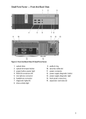
line-out connector Small Form Factor - DisplayPort connector 10. serial connector 3. network activity light 6. VGA connector 10. Back Panel View of Mini-Tower And Desktop 1. USB 2.0 connectors (6) 9. mouse connector 2. keyboard connector 8. ... connector 2. serial connector 6. network connector 5. keyboard connector 8. network connector 4. Mini-Tower And Desktop - Back Panel Figure 5. link integrity light 3. network activity light 5. Back Panel 7. VGA connector 11. line-in /microphone connector 5 Back Panel View Of Small Form Factor 1. link integrity...
line-out connector Small Form Factor - DisplayPort connector 10. serial connector 3. network activity light 6. VGA connector 10. Back Panel View of Mini-Tower And Desktop 1. USB 2.0 connectors (6) 9. mouse connector 2. keyboard connector 8. ... connector 2. serial connector 6. network connector 5. keyboard connector 8. network connector 4. Mini-Tower And Desktop - Back Panel Figure 5. link integrity light 3. network activity light 5. Back Panel 7. VGA connector 11. line-in /microphone connector 5 Back Panel View Of Small Form Factor 1. link integrity...
View
Page 10
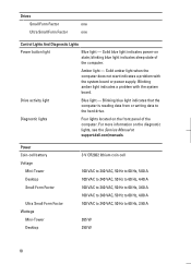
...90 A 265 W 250 W 10 Drive activity light Blue light - blinking blue light indicates sleep state of the computer. Diagnostic lights Four lights located on the front panel of the computer. Drives Small Form Factor one Ultra Small Form Factor one Control Lights And Diagnostic Lights Power button light Blue light - Solid amber light when the computer does not start indicates...3.60 A 100 VAC to 240 VAC, 50 Hz to 60 Hz, 4.00 A 100 VAC to 240 VAC, 50 Hz to the hard drive. Solid blue light indicates power-on the diagnostic lights, see the Service Manual at support.dell.com/manuals.
...90 A 265 W 250 W 10 Drive activity light Blue light - blinking blue light indicates sleep state of the computer. Diagnostic lights Four lights located on the front panel of the computer. Drives Small Form Factor one Ultra Small Form Factor one Control Lights And Diagnostic Lights Power button light Blue light - Solid amber light when the computer does not start indicates...3.60 A 100 VAC to 240 VAC, 50 Hz to 60 Hz, 4.00 A 100 VAC to 240 VAC, 50 Hz to the hard drive. Solid blue light indicates power-on the diagnostic lights, see the Service Manual at support.dell.com/manuals.

Technical Guidebook
Page 3
... 13 Back Panel Connectors 14 Expansion card slots(4) 15 Security cable slot 16 Padlock Ring BACK PANEL CONNECTORS 1 Mouse Connector 7 Keyboard Connector 2 Link Integrity Light 8 USB Connectors (6) 3 Network Connector 4 Network Activity Light 5 Serial connector 6 Line-out Connector 9 Display Port Connector 10 VGA Connector 11 Line-in/Microphone connector 3 DELL™ OPTIPLEX™ 790 TECHNICAL GUIDEBOOK -
... 13 Back Panel Connectors 14 Expansion card slots(4) 15 Security cable slot 16 Padlock Ring BACK PANEL CONNECTORS 1 Mouse Connector 7 Keyboard Connector 2 Link Integrity Light 8 USB Connectors (6) 3 Network Connector 4 Network Activity Light 5 Serial connector 6 Line-out Connector 9 Display Port Connector 10 VGA Connector 11 Line-in/Microphone connector 3 DELL™ OPTIPLEX™ 790 TECHNICAL GUIDEBOOK -

Technical Guidebook
Page 5
... Panel Connectors 13 Expansion card slots(4) 14 Power Supply Diagnostic Light 15 Power Supply Diagnostic Button BACK PANEL CONNECTORS 1 Mouse Connector 7 Keyboard Connector 2 Link Integrity Light 8 USB Connectors (6) 3 Network Connector 9 Display Port Connector 4 Network Activity Light 10 VGA Connector 5 Serial connector 6 Line-out Connector 11 Line-in/Microphone connector 5 DELL™ OPTIPLEX™ 790 TECHNICAL GUIDEBOOK -
... Panel Connectors 13 Expansion card slots(4) 14 Power Supply Diagnostic Light 15 Power Supply Diagnostic Button BACK PANEL CONNECTORS 1 Mouse Connector 7 Keyboard Connector 2 Link Integrity Light 8 USB Connectors (6) 3 Network Connector 9 Display Port Connector 4 Network Activity Light 10 VGA Connector 5 Serial connector 6 Line-out Connector 11 Line-in/Microphone connector 5 DELL™ OPTIPLEX™ 790 TECHNICAL GUIDEBOOK -
Technical Guidebook
Page 7
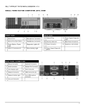
... Supply Diagnostic Light 14 Back Panel Connectors 15 Expansion card slots(2) 12 Power Supply Diagnostic Button BACK PANEL CONNECTORS 1 Mouse Connector 7 Keyboard Connector 2 Serial connector 8 Display Port Connector 3 Link Integrity Light 9 VGA Connector 4 Network Connector 10 USB Connectors (6) 5 Network Activity Light 6 Line-out Connector 11 Line-in/Microphone connector 7 DELL™ OPTIPLEX™ 790 TECHNICAL GUIDEBOOK...
... Supply Diagnostic Light 14 Back Panel Connectors 15 Expansion card slots(2) 12 Power Supply Diagnostic Button BACK PANEL CONNECTORS 1 Mouse Connector 7 Keyboard Connector 2 Serial connector 8 Display Port Connector 3 Link Integrity Light 9 VGA Connector 4 Network Connector 10 USB Connectors (6) 5 Network Activity Light 6 Line-out Connector 11 Line-in/Microphone connector 7 DELL™ OPTIPLEX™ 790 TECHNICAL GUIDEBOOK...
Technical Guidebook
Page 9
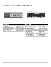
DELL™ OPTIPLEX™ 790 TECHNICAL GUIDEBOOK - V 1.6 ULTRA SMALL FORM FACTOR COMPUTER (USFF) VIEW FRONT VIEW 1 Optical Drive 2 Optical Drive Eject Button 3 Power Button, Power Light 4 Drive Activity Light 5 Diagnostic Lights (4) 6 Headphone Connector 7 Microphone Connector 8 USB Connectors (2) BACK VIEW 9 Wi-Fi Antenna (optional) 10 Network Activity Light 11 Captive Thumbscrew 12 Padlock Ring 13 Security Cable Slot 14...
DELL™ OPTIPLEX™ 790 TECHNICAL GUIDEBOOK - V 1.6 ULTRA SMALL FORM FACTOR COMPUTER (USFF) VIEW FRONT VIEW 1 Optical Drive 2 Optical Drive Eject Button 3 Power Button, Power Light 4 Drive Activity Light 5 Diagnostic Lights (4) 6 Headphone Connector 7 Microphone Connector 8 USB Connectors (2) BACK VIEW 9 Wi-Fi Antenna (optional) 10 Network Activity Light 11 Captive Thumbscrew 12 Padlock Ring 13 Security Cable Slot 14...


