
View
Page 1
.... power connector 13. optical-drive bay (optional) 3. drive activity light 10. security-cable slot 16. padlock ring Regulatory Model: D09M, D05D, D03S, D01U Regulatory Type: D09M001, D05D001, D03S001, D01U002 2011 - 02 optical drive (optional) 7. expansion-card slots (4) 15. Front And Back View Of Mini-Tower 1. power button, power light 2. optical-drive eject button 8. back panel connectors 14. headphone connector 4. USB 2.0 connectors (4) 9. Mini-Tower - microphone connector 5. diagnostic lights (4) 6. power supply diagnostic button 12. Dell OptiPlex 790 Setup And...
.... power connector 13. optical-drive bay (optional) 3. drive activity light 10. security-cable slot 16. padlock ring Regulatory Model: D09M, D05D, D03S, D01U Regulatory Type: D09M001, D05D001, D03S001, D01U002 2011 - 02 optical drive (optional) 7. expansion-card slots (4) 15. Front And Back View Of Mini-Tower 1. power button, power light 2. optical-drive eject button 8. back panel connectors 14. headphone connector 4. USB 2.0 connectors (4) 9. Mini-Tower - microphone connector 5. diagnostic lights (4) 6. power supply diagnostic button 12. Dell OptiPlex 790 Setup And...
View
Page 3
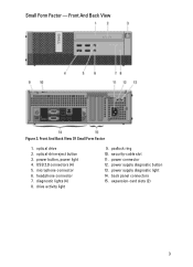
microphone connector 6. drive activity light 9. security-cable slot 11. power supply diagnostic button 13. Front And Back View Of Small Form Factor 1. USB 2.0 connectors (4) 5. back panel connectors 15. power button, power light 4. optical drive 2. Front And Back View Figure 3. headphone connector 7. power connector 12. power supply diagnostic light 14. expansion-card slots (2) 3 Small Form Factor - padlock ring 10. diagnostic lights (4) 8. optical-drive eject button 3.
microphone connector 6. drive activity light 9. security-cable slot 11. power supply diagnostic button 13. Front And Back View Of Small Form Factor 1. USB 2.0 connectors (4) 5. back panel connectors 15. power button, power light 4. optical drive 2. Front And Back View Figure 3. headphone connector 7. power connector 12. power supply diagnostic light 14. expansion-card slots (2) 3 Small Form Factor - padlock ring 10. diagnostic lights (4) 8. optical-drive eject button 3.
View
Page 5
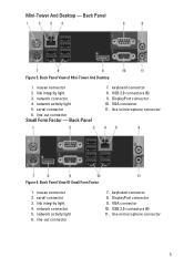
... And Desktop 1. network activity light 5. Back Panel 7. link integrity light 4. keyboard connector 8. mouse connector 2. serial connector 6. line-out connector Small Form Factor - line-in /microphone connector Figure 6. keyboard connector 8. line-out connector 7. Back Panel Figure 5. line-in /microphone connector 5 Back Panel View Of Small Form Factor 1. Mini-Tower And Desktop - serial connector 3. VGA connector 10. network connector 4. network connector 5. network activity light 6. DisplayPort connector 10. mouse connector 2. USB 2.0 connectors...
... And Desktop 1. network activity light 5. Back Panel 7. link integrity light 4. keyboard connector 8. mouse connector 2. serial connector 6. line-out connector Small Form Factor - line-in /microphone connector Figure 6. keyboard connector 8. line-out connector 7. Back Panel Figure 5. line-in /microphone connector 5 Back Panel View Of Small Form Factor 1. Mini-Tower And Desktop - serial connector 3. VGA connector 10. network connector 4. network connector 5. network activity light 6. DisplayPort connector 10. mouse connector 2. USB 2.0 connectors...
View
Page 7
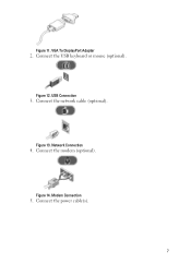
Figure 11. Figure 13. Modem Connection 5. Connect the USB keyboard or mouse (optional). VGA To DisplayPort Adapter 2. USB Connection 3. Connect the network cable (optional). Connect the modem (optional). Connect the power cable(s). 7 Figure 14. Figure 12. Network Connection 4.
Figure 11. Figure 13. Modem Connection 5. Connect the USB keyboard or mouse (optional). VGA To DisplayPort Adapter 2. USB Connection 3. Connect the network cable (optional). Connect the modem (optional). Connect the power cable(s). 7 Figure 14. Figure 12. Network Connection 4.
View
Page 10
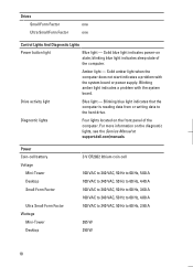
blinking blue light indicates sleep state of the computer. Drive activity light Blue light - Solid amber light when the computer does not start indicates a problem with the system board. Diagnostic lights Four lights located on the diagnostic lights, see the Service Manual at support.dell.com/manuals. Blinking amber light indicates a problem with the system board or power supply. Amber light - For more information on the front panel of the computer. Power Coin-cell battery Voltage Mini-Tower Desktop Small Form Factor Ultra...
blinking blue light indicates sleep state of the computer. Drive activity light Blue light - Solid amber light when the computer does not start indicates a problem with the system board. Diagnostic lights Four lights located on the diagnostic lights, see the Service Manual at support.dell.com/manuals. Blinking amber light indicates a problem with the system board or power supply. Amber light - For more information on the front panel of the computer. Power Coin-cell battery Voltage Mini-Tower Desktop Small Form Factor Ultra...
Technical Guidebook
Page 2
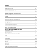
... Computer (USFF) View MARKETING SYSTEM CONFIGURATIONS Operating System, Chipset Processor Memory Drives and Removable Storage, System Expansion Slots Graphics/Video Controller External Ports/Connectors Communications-Network Adapter (NIC) Audio and Speakers, Keyboard and Mouse Security, Service and Support, Software DETAILED ENGINEERING SPECIFICATIONS System Dimensions (Physical) System Expansion Slots System Level Environmental and Operating Conditions Power Audio Communications Graphics/Video Controller Hard Drives Optical Drive BIOS Defaults Chassis Enclosure and Ventilation Requirements...
... Computer (USFF) View MARKETING SYSTEM CONFIGURATIONS Operating System, Chipset Processor Memory Drives and Removable Storage, System Expansion Slots Graphics/Video Controller External Ports/Connectors Communications-Network Adapter (NIC) Audio and Speakers, Keyboard and Mouse Security, Service and Support, Software DETAILED ENGINEERING SPECIFICATIONS System Dimensions (Physical) System Expansion Slots System Level Environmental and Operating Conditions Power Audio Communications Graphics/Video Controller Hard Drives Optical Drive BIOS Defaults Chassis Enclosure and Ventilation Requirements...

Technical Guidebook
Page 3
... Drive (optional) 7 Optical Drive Eject Button 8 USB 2.0 Connectors (4) 9 Drive Activity Light BACK VIEW 10 Power Supply Diagnostic Light 11 Power Supply Diagnostic Button 12 Power Connector 13 Back Panel Connectors 14 Expansion card slots(4) 15 Security cable slot 16 Padlock Ring BACK PANEL CONNECTORS 1 Mouse Connector 7 Keyboard Connector 2 Link Integrity Light 8 USB Connectors (6) 3 Network Connector 4 Network Activity Light 5 Serial connector 6 Line-out Connector 9 Display Port Connector 10 VGA Connector 11 Line-in/Microphone connector 3 DELL™ OPTIPLEX™ 790 TECHNICAL...
... Drive (optional) 7 Optical Drive Eject Button 8 USB 2.0 Connectors (4) 9 Drive Activity Light BACK VIEW 10 Power Supply Diagnostic Light 11 Power Supply Diagnostic Button 12 Power Connector 13 Back Panel Connectors 14 Expansion card slots(4) 15 Security cable slot 16 Padlock Ring BACK PANEL CONNECTORS 1 Mouse Connector 7 Keyboard Connector 2 Link Integrity Light 8 USB Connectors (6) 3 Network Connector 4 Network Activity Light 5 Serial connector 6 Line-out Connector 9 Display Port Connector 10 VGA Connector 11 Line-in/Microphone connector 3 DELL™ OPTIPLEX™ 790 TECHNICAL...

Technical Guidebook
Page 5
DELL™ OPTIPLEX™ 790 TECHNICAL GUIDEBOOK - V 1.6 DESKTOP COMPUTER (DT) VIEW FRONT VIEW 1 Optical Drive 2 Optical Drive Eject Button 3 Power Button, Power Light 4 USB Connectors (4) 5 Microphone Connector 6 Headphone Connector 7 Drive Activity Light 8 Diagnostic Lights (4) BACK VIEW 9 Padlock Ring 10 Security cable slot 11 Power Connector 12 Back Panel Connectors 13 Expansion card slots(4) 14 Power Supply Diagnostic Light 15 Power Supply Diagnostic Button BACK PANEL CONNECTORS 1 Mouse Connector 7 Keyboard Connector 2 Link Integrity Light 8 USB Connectors (6) 3 Network ...
DELL™ OPTIPLEX™ 790 TECHNICAL GUIDEBOOK - V 1.6 DESKTOP COMPUTER (DT) VIEW FRONT VIEW 1 Optical Drive 2 Optical Drive Eject Button 3 Power Button, Power Light 4 USB Connectors (4) 5 Microphone Connector 6 Headphone Connector 7 Drive Activity Light 8 Diagnostic Lights (4) BACK VIEW 9 Padlock Ring 10 Security cable slot 11 Power Connector 12 Back Panel Connectors 13 Expansion card slots(4) 14 Power Supply Diagnostic Light 15 Power Supply Diagnostic Button BACK PANEL CONNECTORS 1 Mouse Connector 7 Keyboard Connector 2 Link Integrity Light 8 USB Connectors (6) 3 Network ...
Technical Guidebook
Page 6
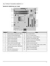
DELL™ OPTIPLEX™ 790 TECHNICAL GUIDEBOOK - V 1.6 DESKTOP COMPUTER (DT) VIEW Number Name Number Name 1 Internal speaker connector(INT_SPKR) 13 PCI connector(SLOT3) 2 Front IO connector(FRONTPANEL) 14 PCI-e 4x connector(SLOT4) 3 Thermal sensor connector(THRM_2) 15 Thermal sensor connector(THRM_1) 4 SATA 0 connector(SATA0) 16 System fan connector(FAN_HDD) 5 SATA 1 connector(SATA1) 17 P2 power connector(12V_PWRCONN) 6 SATA 2 connector(SATA2) 18 Processor connector(N/A) 7 Internal USB connector(INT_USB) 19 CPU fan connector(FAN_CPU) 8 LPC debug connector(...
DELL™ OPTIPLEX™ 790 TECHNICAL GUIDEBOOK - V 1.6 DESKTOP COMPUTER (DT) VIEW Number Name Number Name 1 Internal speaker connector(INT_SPKR) 13 PCI connector(SLOT3) 2 Front IO connector(FRONTPANEL) 14 PCI-e 4x connector(SLOT4) 3 Thermal sensor connector(THRM_2) 15 Thermal sensor connector(THRM_1) 4 SATA 0 connector(SATA0) 16 System fan connector(FAN_HDD) 5 SATA 1 connector(SATA1) 17 P2 power connector(12V_PWRCONN) 6 SATA 2 connector(SATA2) 18 Processor connector(N/A) 7 Internal USB connector(INT_USB) 19 CPU fan connector(FAN_CPU) 8 LPC debug connector(...
Technical Guidebook
Page 7
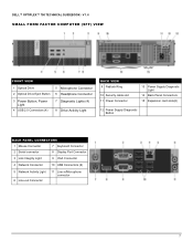
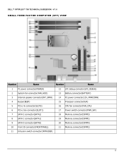
DELL™ OPTIPLEX™ 790 TECHNICAL GUIDEBOOK - V 1.6 SMALL FORM FACTOR COMPUTER (SFF) VIEW FRONT VIEW 1 Optical Drive 2 Optical Drive Eject Button 5 Microphone Connector 6 Headphone Connector 3 Power Button, Power Light 4 USB 2.0 Connectors (4) 7 Diagnostic Lights (4) 8 Drive Activity Light BACK VIEW 9 Padlock Ring 10 Security cable slot 11 Power Connector 13 Power Supply Diagnostic Light 14 Back Panel Connectors 15 Expansion card slots(2) 12 Power Supply Diagnostic Button BACK PANEL CONNECTORS 1 Mouse Connector 7 Keyboard Connector 2 Serial connector 8 Display Port ...
DELL™ OPTIPLEX™ 790 TECHNICAL GUIDEBOOK - V 1.6 SMALL FORM FACTOR COMPUTER (SFF) VIEW FRONT VIEW 1 Optical Drive 2 Optical Drive Eject Button 5 Microphone Connector 6 Headphone Connector 3 Power Button, Power Light 4 USB 2.0 Connectors (4) 7 Diagnostic Lights (4) 8 Drive Activity Light BACK VIEW 9 Padlock Ring 10 Security cable slot 11 Power Connector 13 Power Supply Diagnostic Light 14 Back Panel Connectors 15 Expansion card slots(2) 12 Power Supply Diagnostic Button BACK PANEL CONNECTORS 1 Mouse Connector 7 Keyboard Connector 2 Serial connector 8 Display Port ...
Technical Guidebook
Page 8
... Battery connector(BATTERY) 3 Internal speaker connector(INT_SPKR) 14 P2 power connector(12V_PWRCONN) 4 Buzzer(BEEP) 15 Processor connector(N/A) 5 PCI-e 4x connector(SLOT2) 16 CPU fan connector(FAN_CPU) 6 PCI-e 16x connector(SLOT1) 17 Power switch connector(PWR_SW) 7 SATA 2 connector(SATA2) 18 Memory connector(DIMM3) 8 SATA 1 connector(SATA1) 19 Memory connector(DIMM1) 9 SATA 0 connector(SATA0) 20 Memory connector(DIMM4) 10 Front IO connector(FRONTPANEL) 21 Memory connector(DIMM2) 11 Intrusion switch connector(INTRUDER) 8 DELL™ OPTIPLEX™ 790 TECHNICAL GUIDEBOOK...
... Battery connector(BATTERY) 3 Internal speaker connector(INT_SPKR) 14 P2 power connector(12V_PWRCONN) 4 Buzzer(BEEP) 15 Processor connector(N/A) 5 PCI-e 4x connector(SLOT2) 16 CPU fan connector(FAN_CPU) 6 PCI-e 16x connector(SLOT1) 17 Power switch connector(PWR_SW) 7 SATA 2 connector(SATA2) 18 Memory connector(DIMM3) 8 SATA 1 connector(SATA1) 19 Memory connector(DIMM1) 9 SATA 0 connector(SATA0) 20 Memory connector(DIMM4) 10 Front IO connector(FRONTPANEL) 21 Memory connector(DIMM2) 11 Intrusion switch connector(INTRUDER) 8 DELL™ OPTIPLEX™ 790 TECHNICAL GUIDEBOOK...
Technical Guidebook
Page 9
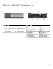
...(USFF) VIEW FRONT VIEW 1 Optical Drive 2 Optical Drive Eject Button 3 Power Button, Power Light 4 Drive Activity Light 5 Diagnostic Lights (4) 6 Headphone Connector 7 Microphone Connector 8 USB Connectors (2) BACK VIEW 9 Wi-Fi Antenna (optional) 10 Network Activity Light 11 Captive Thumbscrew 12 Padlock Ring 13 Security Cable Slot 14 Power Connector 15 Line-Out Connector 16 Line-in/ Microphone Connector 17 Display Port Connector 18 VGA Connector 19 Serial Connector 20 USB Connectors (5) 21 Network Connector 22 Link Integrity Light 9 DELL™ OPTIPLEX™ 790 TECHNICAL GUIDEBOOK -
...(USFF) VIEW FRONT VIEW 1 Optical Drive 2 Optical Drive Eject Button 3 Power Button, Power Light 4 Drive Activity Light 5 Diagnostic Lights (4) 6 Headphone Connector 7 Microphone Connector 8 USB Connectors (2) BACK VIEW 9 Wi-Fi Antenna (optional) 10 Network Activity Light 11 Captive Thumbscrew 12 Padlock Ring 13 Security Cable Slot 14 Power Connector 15 Line-Out Connector 16 Line-in/ Microphone Connector 17 Display Port Connector 18 VGA Connector 19 Serial Connector 20 USB Connectors (5) 21 Network Connector 22 Link Integrity Light 9 DELL™ OPTIPLEX™ 790 TECHNICAL GUIDEBOOK -
Technical Guidebook
Page 11
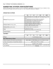
... 11 For more information regarding the configuration of your computer, click Start>Help and Support and select the option to view information about your computer. DELL™ OPTIPLEX™ 790 TECHNICAL GUIDEBOOK - OPERATING SYSTEM Windows 7® operating system Windows Vista® operating system Windows XP® operating system Other OS Media Support CHIPSET Chipset Non-volatile memory on chipset BIOS Configuration SPI (Serial Peripheral Interface) TPM 1.2 Security Device (Trusted Platform Module)1 Non-TPM...
... 11 For more information regarding the configuration of your computer, click Start>Help and Support and select the option to view information about your computer. DELL™ OPTIPLEX™ 790 TECHNICAL GUIDEBOOK - OPERATING SYSTEM Windows 7® operating system Windows Vista® operating system Windows XP® operating system Other OS Media Support CHIPSET Chipset Non-volatile memory on chipset BIOS Configuration SPI (Serial Peripheral Interface) TPM 1.2 Security Device (Trusted Platform Module)1 Non-TPM...

Technical Guidebook
Page 14
... MT Bays: 5.25-inch bay (External Optical) 2 Hard Drives Supported (Internal and External) 2 Optical Drives Supported 2 Interface: SATA 2.0 3 SATA 3.0 1 3.5" Hard Drives: 1TB1 SATA 7200 RPM HDD X 500GB1 SATA 7200 RPM HDD X 320GB1 SATA 7200 RPM HDD X 250GB1 SATA 7200 RPM HDD X 2.5" Hard Drives: 500GB1 SATA 7200 RPM HDD X 500GB1 SATA 7200 RPM Hybrid HDD X 320GB1 with and without FIPS Full DISK EnCRYPTION SATA HDD (available after May19, 2011) X 250GB1 SATA 7200 RPM HDD X 128GB1 SATA Solid State Drive HDD X DT SFF USFF 1 1 (slim-line) 1 (slim-line...
... MT Bays: 5.25-inch bay (External Optical) 2 Hard Drives Supported (Internal and External) 2 Optical Drives Supported 2 Interface: SATA 2.0 3 SATA 3.0 1 3.5" Hard Drives: 1TB1 SATA 7200 RPM HDD X 500GB1 SATA 7200 RPM HDD X 320GB1 SATA 7200 RPM HDD X 250GB1 SATA 7200 RPM HDD X 2.5" Hard Drives: 500GB1 SATA 7200 RPM HDD X 500GB1 SATA 7200 RPM Hybrid HDD X 320GB1 with and without FIPS Full DISK EnCRYPTION SATA HDD (available after May19, 2011) X 250GB1 SATA 7200 RPM HDD X 128GB1 SATA Solid State Drive HDD X DT SFF USFF 1 1 (slim-line) 1 (slim-line...

Technical Guidebook
Page 15
...2 1 For hard drives, GB means 1 billion bytes; V 1.6 DRIVES AND REMOVABLE STORAGE Optical Drive: (SFF/USFF require slim-line optical drive) DVD+/-RW2 DVD-ROM3 Media Card Reader: Dell 19 in 1 Media Card Reader MT SATA 1.5Gbit/s SATA 1.5Gbit/s X DT SATA 1.5Gbit/s SATA 1.5Gbit/s X SFF SATA 1.5Gbit/s SATA 1.5Gbit/s USFF SATA 1.5Gbit/s SATA 1.5Gbit/s NOTE: Dell 19 in card location and priority: PCI: 1394; PCIe x4: GFX, USB 3.0, Serial, Parallel/Serial, NIC, Wireless; NOTE: Add in 1 Media Card Reader is supported via firmware modifications. 15 DELL™ OPTIPLEX™ 790 TECHNICAL...
...2 1 For hard drives, GB means 1 billion bytes; V 1.6 DRIVES AND REMOVABLE STORAGE Optical Drive: (SFF/USFF require slim-line optical drive) DVD+/-RW2 DVD-ROM3 Media Card Reader: Dell 19 in 1 Media Card Reader MT SATA 1.5Gbit/s SATA 1.5Gbit/s X DT SATA 1.5Gbit/s SATA 1.5Gbit/s X SFF SATA 1.5Gbit/s SATA 1.5Gbit/s USFF SATA 1.5Gbit/s SATA 1.5Gbit/s NOTE: Dell 19 in card location and priority: PCI: 1394; PCIe x4: GFX, USB 3.0, Serial, Parallel/Serial, NIC, Wireless; NOTE: Add in 1 Media Card Reader is supported via firmware modifications. 15 DELL™ OPTIPLEX™ 790 TECHNICAL...

Technical Guidebook
Page 16
... Serial via optional PCIex1 card Network Connector (RJ-45) PS/2 1394 Controller via optional PCI card USB 3.0 via optional PCIex1 card Video: VGA DisplayPort Audio: Line in for microphone Line in for microphone or stereo Line out for headphones or speakers MT DT SFF Optional FH card 4 Front, 6 Rear 1 Rear Optional LP card Optional FH card Optional FH card 1 Rear 2 Rear Optional LP card Optional LP card 1 Rear 1 Rear 1 Front 1 Rear 1 Front, 1 Rear USFF 2 Front, 5 Rear 16 DELL™ OPTIPLEX™ 790 TECHNICAL GUIDEBOOK - MT Intel HD Graphics [with Celeron/Pentium class CPU...
... Serial via optional PCIex1 card Network Connector (RJ-45) PS/2 1394 Controller via optional PCI card USB 3.0 via optional PCIex1 card Video: VGA DisplayPort Audio: Line in for microphone Line in for microphone or stereo Line out for headphones or speakers MT DT SFF Optional FH card 4 Front, 6 Rear 1 Rear Optional LP card Optional FH card Optional FH card 1 Rear 2 Rear Optional LP card Optional LP card 1 Rear 1 Rear 1 Front 1 Rear 1 Front, 1 Rear USFF 2 Front, 5 Rear 16 DELL™ OPTIPLEX™ 790 TECHNICAL GUIDEBOOK - MT Intel HD Graphics [with Celeron/Pentium class CPU...
Technical Guidebook
Page 17
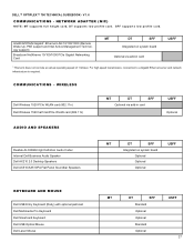
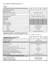
... Gigabit1 Ethernet LAN 10/100/1000 (Remote Wake Up, PXE support and Intel Active Management Technology support) Broadcom NetXtreme 10/100/1000 PCIe Gigabit Networking Card MT DT SFF Integrated on system board Optional via add-in card USFF 1 This term does not connote an actual operating speed of 1 Gb/sec. DELL™ OPTIPLEX™ 790 TECHNICAL GUIDEBOOK - SFF supports low profile card. COMMUNICATIONS - V 1.6 COMMUNICATIONS - For high speed transmission, connection to a Gigabit Ethernet server and network...
... Gigabit1 Ethernet LAN 10/100/1000 (Remote Wake Up, PXE support and Intel Active Management Technology support) Broadcom NetXtreme 10/100/1000 PCIe Gigabit Networking Card MT DT SFF Integrated on system board Optional via add-in card USFF 1 This term does not connote an actual operating speed of 1 Gb/sec. DELL™ OPTIPLEX™ 790 TECHNICAL GUIDEBOOK - SFF supports low profile card. COMMUNICATIONS - V 1.6 COMMUNICATIONS - For high speed transmission, connection to a Gigabit Ethernet server and network...
Technical Guidebook
Page 23
...) 23 INTEGRATED INTEL® 82579 GIGABIT1 ETHERNET LAN 10/100/1000 External Connector Type Data Rates supported Controller Details Controller bus architecture Integrated memory Data transfer mode (example Bus-Master DMA) Power consumption (full operation per data rate connection speed) Power consumption (standby operation) IEEE standards compliance (example 802.1P) Hardware Certifications (example FCC, B, GS mark...) Boot ROM Support Network Transfer Mode (example Full Duplex, Half Duplex) Network Transfer Rate (example 10BASE-T (half...
...) 23 INTEGRATED INTEL® 82579 GIGABIT1 ETHERNET LAN 10/100/1000 External Connector Type Data Rates supported Controller Details Controller bus architecture Integrated memory Data transfer mode (example Bus-Master DMA) Power consumption (full operation per data rate connection speed) Power consumption (standby operation) IEEE standards compliance (example 802.1P) Hardware Certifications (example FCC, B, GS mark...) Boot ROM Support Network Transfer Mode (example Full Duplex, Half Duplex) Network Transfer Rate (example 10BASE-T (half...
Technical Guidebook
Page 26
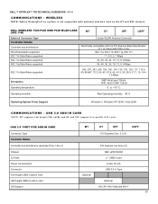
... with optional wireless card on the DT and SFF chassis. V 1.6 COMMUNICATIONS - USB 3.0 PORT PCIE ADD-IN CARD Connector Type Controller Details Controller bus architecture (example PCIe 1.0a x1) Chipset IO Ports Power Consumption Connector Full height USB3.0 add-in card Half height USB3.0 add-in card OS Support MT DT SFF USFF PCI Express Gen. 2.0 X1 PCI Express one lane (x1) NEC µPD720200 2 * USB3.0 port Under 30 mA USB 3.0 A Type Optional Optional Win XP, Win Vista...
... with optional wireless card on the DT and SFF chassis. V 1.6 COMMUNICATIONS - USB 3.0 PORT PCIE ADD-IN CARD Connector Type Controller Details Controller bus architecture (example PCIe 1.0a x1) Chipset IO Ports Power Consumption Connector Full height USB3.0 add-in card Half height USB3.0 add-in card OS Support MT DT SFF USFF PCI Express Gen. 2.0 X1 PCI Express one lane (x1) NEC µPD720200 2 * USB3.0 port Under 30 mA USB 3.0 A Type Optional Optional Win XP, Win Vista...
Technical Guidebook
Page 42
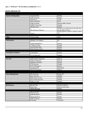
...;: SATA-0 Password: Power Management Maintenance AC Recovery: Auto On Time: Deep Sleep Control: Fan Control Override: Wake on LAN: Service Tag: Asset Tag: SERR Message: Numlock LED: USB Emulation: Keyboard Errors: POST HotKeys: Fast Boot: Enable Enable COM1 AHCI Enable USB Controller Disable Enable Enable (Front USB, Rear Dual USB, Rear Quad USB, PCI Slot) Enable (SATA-0, SATA-1, SATA-2, SATA -3) Auto All Enable Disable Enable Enable Enable Disable Not set Not set Enable Disable Enable Deactivate Not set Power Off Disable Disable Disable Disable Set by the factory Optional User Entry Enable...
...;: SATA-0 Password: Power Management Maintenance AC Recovery: Auto On Time: Deep Sleep Control: Fan Control Override: Wake on LAN: Service Tag: Asset Tag: SERR Message: Numlock LED: USB Emulation: Keyboard Errors: POST HotKeys: Fast Boot: Enable Enable COM1 AHCI Enable USB Controller Disable Enable Enable (Front USB, Rear Dual USB, Rear Quad USB, PCI Slot) Enable (SATA-0, SATA-1, SATA-2, SATA -3) Auto All Enable Disable Enable Enable Enable Disable Not set Not set Enable Disable Enable Deactivate Not set Power Off Disable Disable Disable Disable Set by the factory Optional User Entry Enable...


