
User's Guide
Page 4
... 83 Removing the Processor 83 Installing the Processor 85 Power Supply 89 Replacing the Power Supply 89 DC Power Connectors 91 4 Desktop Computer 97 About Your Desktop Computer 97 Front View 97 Back View 98 Back-Panel Connectors 99 Inside Your Computer 101 System Board Components 102 Desktop Computer (Model # DCNE) Specifications 105 I/O Panel... Cards, and PS/2 Serial Port Adapters 135 PCI Cards 135 PCI Express and DVI Cards 146 PS/2 Serial Port Adapters 163 Power Supply 169 Replacing the Power Supply 169 DC Power Connectors 171 Removing the Computer Cover 177 4 Contents
... 83 Removing the Processor 83 Installing the Processor 85 Power Supply 89 Replacing the Power Supply 89 DC Power Connectors 91 4 Desktop Computer 97 About Your Desktop Computer 97 Front View 97 Back View 98 Back-Panel Connectors 99 Inside Your Computer 101 System Board Components 102 Desktop Computer (Model # DCNE) Specifications 105 I/O Panel... Cards, and PS/2 Serial Port Adapters 135 PCI Cards 135 PCI Express and DVI Cards 146 PS/2 Serial Port Adapters 163 Power Supply 169 Replacing the Power Supply 169 DC Power Connectors 171 Removing the Computer Cover 177 4 Contents
User's Guide
Page 101
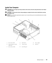
... shock, always unplug your computer from the system board. 3 2 1 4 5 6 8 1 drive release latch 4 chassis intrusion switch (optional) 7 heat sink assembly 2 optical drive 5 system board 8 front I/O panel 7 3 power supply 6 card slots Desktop Computer 101 Inside Your Computer CAUTION: Before you do not accidentally disconnect cables from the electrical outlet before removing the computer cover.
... shock, always unplug your computer from the system board. 3 2 1 4 5 6 8 1 drive release latch 4 chassis intrusion switch (optional) 7 heat sink assembly 2 optical drive 5 system board 8 front I/O panel 7 3 power supply 6 card slots Desktop Computer 101 Inside Your Computer CAUTION: Before you do not accidentally disconnect cables from the electrical outlet before removing the computer cover.
User's Guide
Page 109
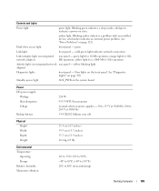
... light adapter) Diagnostic lights front panel - orange light for 100Mb operation; Standby power light AUX_PWR on page 330. See "Diagnostic Lights" on the system board Power DC power supply: Wattage Heat dissipation Voltage Backup battery 280 W 955.39 BTU/hr maximum manual selection power supplies - 90 to 135 V at 50/60 Hz; 180 to 265 V at... vibration: 10° to 35°C (50° to 95°F) -40° to 65°C (-40° to 149°F) 20% to 80% (noncondensing) Desktop Computer 109 Blinking green indicates a sleep mode; green Link light front panel -
... light adapter) Diagnostic lights front panel - orange light for 100Mb operation; Standby power light AUX_PWR on page 330. See "Diagnostic Lights" on the system board Power DC power supply: Wattage Heat dissipation Voltage Backup battery 280 W 955.39 BTU/hr maximum manual selection power supplies - 90 to 135 V at 50/60 Hz; 180 to 265 V at... vibration: 10° to 35°C (50° to 95°F) -40° to 65°C (-40° to 149°F) 20% to 80% (noncondensing) Desktop Computer 109 Blinking green indicates a sleep mode; green Link light front panel -

User's Guide
Page 169
...these cables properly when you remove them to prevent their being pinched or crimped. 3 Remove the two screws that attach the power supply to components inside your computer, discharge static electricity from your body before you begin any of your computer's electronic components. ... by touching an unpainted metal surface on the computer chassis. 1 Follow the procedures in the Product Information Guide. Desktop Computer 169 Power Supply Replacing the Power Supply CAUTION: Before you touch any of the procedures in this section, follow the safety instructions located in "Before You...
...these cables properly when you remove them to prevent their being pinched or crimped. 3 Remove the two screws that attach the power supply to components inside your computer, discharge static electricity from your body before you begin any of your computer's electronic components. ... by touching an unpainted metal surface on the computer chassis. 1 Follow the procedures in the Product Information Guide. Desktop Computer 169 Power Supply Replacing the Power Supply CAUTION: Before you touch any of the procedures in this section, follow the safety instructions located in "Before You...
User's Guide
Page 170
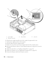
... by approximately 1 inch. 7 Lift the power supply up and out of the computer. 8 Slide the replacement power supply into place. 9 Replace the screws that secure the power supply to the back of the computer chassis. 10 Reconnect the DC power cables (see "System Board Components" on page... 102 for connector locations). 11 Replace the optical drive (see "Installing an Optical Drive" on page 116). 12 Replace the computer cover (see "Replacing the Computer Cover" on page 297). 13 Connect the AC power cable to the AC power connector. 170 Desktop...
... by approximately 1 inch. 7 Lift the power supply up and out of the computer. 8 Slide the replacement power supply into place. 9 Replace the screws that secure the power supply to the back of the computer chassis. 10 Reconnect the DC power cables (see "System Board Components" on page... 102 for connector locations). 11 Replace the optical drive (see "Installing an Optical Drive" on page 116). 12 Replace the computer cover (see "Replacing the Computer Cover" on page 297). 13 Connect the AC power cable to the AC power connector. 170 Desktop...
User's Guide
Page 329
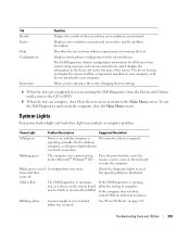
... and Utilities 329 Solid yellow The Dell Diagnostics is running a If the Dell Diagnostics is running the Dell Diagnostics from system setup, memory, and various internal tests, and it displays the information in the device list in a power-saving mode (Microsoft® Windows®...installed. times and then turns off Check the diagnostic lights to wake the computer. Blinking yellow A power supply or system board failure has occurred. On the desktop computer, a solid green light indicates a network connection. Displays error conditions encountered, error codes, and ...
... and Utilities 329 Solid yellow The Dell Diagnostics is running a If the Dell Diagnostics is running the Dell Diagnostics from system setup, memory, and various internal tests, and it displays the information in the device list in a power-saving mode (Microsoft® Windows®...installed. times and then turns off Check the diagnostic lights to wake the computer. Blinking yellow A power supply or system board failure has occurred. On the desktop computer, a solid green light indicates a network connection. Displays error conditions encountered, error codes, and ...
User's Guide
Page 368
... format. Zip drive - wallpaper - wireless local area network. extended graphics array - Zip - You can supply 66 W of interconnected computers that allows a computer chip to be changed or destroyed. WHr - WLAN -...or its write-protect tab to protect data from being changed . A series of power for 1 hour or 33 W for video cards and controllers that uses 3.5-inch ..., which has a filename extension of a battery. The background pattern or picture on the Windows desktop. You can also scan in your wallpaper through the Windows Control Panel. A video standard for ...
... format. Zip drive - wallpaper - wireless local area network. extended graphics array - Zip - You can supply 66 W of interconnected computers that allows a computer chip to be changed or destroyed. WHr - WLAN -...or its write-protect tab to protect data from being changed . A series of power for 1 hour or 33 W for video cards and controllers that uses 3.5-inch ..., which has a filename extension of a battery. The background pattern or picture on the Windows desktop. You can also scan in your wallpaper through the Windows Control Panel. A video standard for ...


