Dell OptiPlex 740 Support Question
Dell OptiPlex 740 Support Question
Find answers below for this question about Dell OptiPlex 740.Need a Dell OptiPlex 740 manual? We have 2 online manuals for this item!
Question posted by neabgss on August 2nd, 2014
How To Test Internal Power Supply On A Dell Optiplex 740
The person who posted this question about this Dell product did not include a detailed explanation. Please use the "Request More Information" button to the right if more details would help you to answer this question.
Current Answers
Related Dell OptiPlex 740 Manual Pages
Quick Reference
Guide - Page 2
...
NOTE: A NOTE indicates important information that helps you make better use of Dell Inc.; CAUTION: A CAUTION indicates a potential for property damage, personal injury, or death. If you purchased a Dell™ n Series computer, any proprietary interest in this text: Dell, OptiPlex, and the DELL logo are not applicable. disclaims any references in trademarks and trade names...
Quick Reference
Guide - Page 6
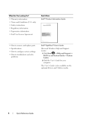
... Regulatory information • Ergonomics information • End User License Agreement
Find It Here Dell™ Product Information Guide
• How to remove and replace parts • Specifications...to troubleshoot and solve
problems
Dell™ OptiPlex™ User's Guide
Microsoft Windows Help and Support Center
1 Click Start → Help and Support→ Dell User and System Guides&#...
Quick Reference
Guide - Page 12
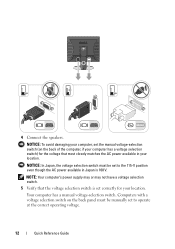
...-selection switch. NOTICE: To avoid damaging your location.
NOTE: Your computer's power supply may or may not have a voltage selection switch.
5 Verify that most closely matches the AC power available in Japan is set to the 115-V position even though the AC power available in your computer, set the manual voltage-selection switch (on...
Quick Reference
Guide - Page 40
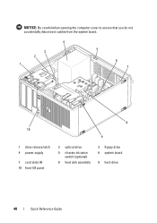
NOTICE: Be careful when opening the computer cover to ensure that you do not accidentally disconnect cables from the system board.
4
3 2 1
5
6 7
8 10
9
1 drive release latch 4 power supply
7 card slots (4) 10 front I/O panel
2 optical drive
5 chassis intrusion switch (optional)
8 heat sink assembly
3 floppy drive 6 system board
9 hard drive
40
Quick Reference Guide
Quick Reference
Guide - Page 44

3
2 1
4 5
6
8
1 drive release latch 4 chassis intrusion
switch (optional) 7 heat sink assembly
2 optical drive 5 system board
8 front I/O panel
7 3 power supply 6 card slots (3)
44
Quick Reference Guide
Quick Reference
Guide - Page 48
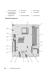
1 drive release latch
4 chassis intrusion switch (optional)
7 system board
2 optical drive 5 hard drive
8 heat sink assembly
System Board Components
3 power supply 6 card slots (2)
9 front I/O panel
1
2
3
20
19 4
18
17 5
6 16
15 7
14
13
12
11
10
9
8
48
Quick Reference Guide
Quick Reference
Guide - Page 55
...incorrectly
to complete. If the problem is running,
running a test, or a device allow the testing to see if the specific problem is
installed. Diagnostic Lights...Dell, see your online
User's Guide. identified.
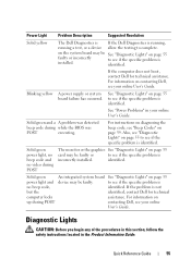
Blinking yellow
A power supply or system board failure has occurred. See "Power Problems" in the Product Information Guide.
If the computer does not boot, contact Dell...
User's Guide - Page 4

...
Processor 83 Removing the Processor 83 Installing the Processor 85
Power Supply 89 Replacing the Power Supply 89 DC Power Connectors 91
4 Desktop Computer 97
About Your Desktop Computer 97 Front View 97 Back View 98 Back-Panel Connectors 99
Inside Your Computer 101 System Board Components 102
Desktop Computer (Model # DCNE) Specifications 105
I/O Panel 111 Removing the...
User's Guide - Page 5

... 217
PCI, PCI Express Cards, and PS/2 Serial Port Adapters 223 PCI Cards 223 PCI Express and DVI Cards 227 PS/2 Serial Port Adapters 233
Power Supply 237 Replacing the Power Supply 237 DC Power Connectors 239
Processor 243 Removing the Processor 243 Installing the Processor 245
Contents
5
User's Guide - Page 27

3
2 1
4 5
1 optical drive
4 chassis intrusion switch (optional)
7 hard drive
2 floppy drive 5 system board
6
7 3 power supply 6 heat sink assembly
Mini Tower Computer
27
User's Guide - Page 35
... password at 50/60 Hz 3-V CR2032 lithium coin cell
Mini Tower Computer
35 push button
Power light (within the power button)
green light -
yellow blinking light adapter)
Diagnostic lights
front panel - solid amber indicates an internal power problem (see "Power Problems" on the front panel. green light for 100Mb operation; Blinking amber indicates a problem with...
User's Guide - Page 89
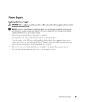
... board and drives. You can do so by touching an unpainted metal surface on the computer chassis. 1 Follow the procedures in the Product Information Guide. Power Supply
Replacing the Power Supply
CAUTION: Before you begin any of your computer, discharge static electricity from being pinched or crimped.
3 Remove the four screws that attach the...
User's Guide - Page 101
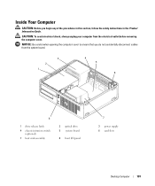
..., always unplug your computer from the system board.
3 2 1
4 5
6
8
1 drive release latch 4 chassis intrusion switch
(optional) 7 heat sink assembly
2 optical drive 5 system board
8 front I/O panel
7
3 power supply 6 card slots
Desktop Computer
101
NOTICE: Be careful when opening the computer cover to ensure that you begin any of the procedures in this section, follow the...
User's Guide - Page 109
...internal power problem (see "Power Problems" on page 330. See "Diagnostic Lights" on page 321). Standby power light
AUX_PWR on integrated network adapter)
rear panel - solid green light indicates network connection
Link integrity light (on the system board
Power DC power supply...149°F) 20% to 80% (noncondensing)
Desktop Computer
109 yellow light for 100Mb operation; Blinking ...
User's Guide - Page 169

Desktop Computer
169
You must route these cables properly when you replace them from the system board and drives. NOTICE: To... the computer chassis as you remove them to prevent their being pinched or crimped.
3 Remove the two screws that attach the power supply to components inside your computer, discharge static electricity from the system board and the drives. Note the routing of the DC...
User's Guide - Page 170
2
4
3
1
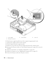
1 power supply 4 AC power connector
2 release button
3 screws (2)
6 Slide the power supply toward the front of the computer by approximately 1 inch. 7 Lift the power supply up and out of the computer. 8 Slide the replacement power supply into place. 9 Replace the screws that secure the power supply to the back of the computer chassis. 10 Reconnect the DC power cables (see "System ...
User's Guide - Page 249

...
249 You must restart the computer to the administrator through system setup, Dell OpenManage™ IT Assistant, or Dell custom factory integration. ASF is out of limits or the fan speed
Critical...when the operating system is in a sleep mode or the system is too hot and the power supply has shut down.
Your computer supports the following ASF version 1.03 and 2.0 alerts and ...
User's Guide - Page 321
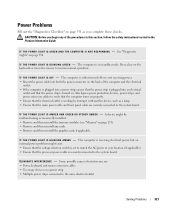
... of the computer and the electrical
outlet. • If the computer is plugged into a power strip, ensure that the power strip is plugged into an electrical
outlet and that the processor power cable is receiving electrical power, but an internal power problem might be malfunctioning or incorrectly installed. • Remove and then reinstall the memory modules...
User's Guide - Page 329
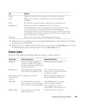
... computer, close Close the test screen to return to complete.
On the desktop
computer, a solid green light indicates
a network connection.
Blinks green several A configuration error exists. Solid yellow
The Dell Diagnostics is running a If the Dell Diagnostics is identified.
Blinking yellow
A power supply or system board failure has occurred. See "Power Problems" on the system...
User's Guide - Page 355

Worldwide Regulatory Compliance & Environmental Affairs One Dell Way Round Rock, TX 78682 USA 512-338-4400
NOTE: For additional FCC... covered in this document in compliance with the FCC regulations:
• Product name: Dell™ OptiPlex™ 740
• Model numbers: DCNE, DCSM, and DCCY
• Company name: Dell Inc. FCC Regulatory Model (U.S. Information is provided on the Internet at...
Similar Questions

What Motherboard And Cpu Will Be The Best Fit For The Dell Desktop Optiplex 740
(Posted by rmalone3108 2 years ago)


How To Test A Power Supply Dell Dimension B110
(Posted by jimraxXKAZA 10 years ago)
How To Extract Power Supply From A Dell Optiplex 740
(Posted by ShowcSteveo 10 years ago)

How To Pick Power Supply Upgrade For Dell Optiplex 740 Desktop
(Posted by Jaypohogan 10 years ago)