Quick Reference Guide
Page 4
Solving Problems 50 Dell Diagnostics 51 System Lights 54 Diagnostic Lights 55 Beep Codes 59 Resolving Software and Hardware Incompatibilities 60 Restoring Your Operating System 61 Reinstalling Your Microsoft Windows Operating System 63 Using the Drivers and Utilities Media 67 Index 71 4 Contents
Solving Problems 50 Dell Diagnostics 51 System Lights 54 Diagnostic Lights 55 Beep Codes 59 Resolving Software and Hardware Incompatibilities 60 Restoring Your Operating System 61 Reinstalling Your Microsoft Windows Operating System 63 Using the Drivers and Utilities Media 67 Index 71 4 Contents
Quick Reference Guide
Page 15
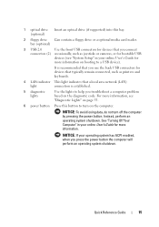
... User's Guide for more information on the computer. bay (optional) 3 USB 2.0 Use the front USB connectors for bootable USB devices (see "Diagnostic Lights" on the diagnostic code. It is established. 5 diagnostic lights Use the lights to help you use the back USB connectors for devices that typically remain connected, such as joysticks or cameras, or for...
... User's Guide for more information on the computer. bay (optional) 3 USB 2.0 Use the front USB connectors for bootable USB devices (see "Diagnostic Lights" on the diagnostic code. It is established. 5 diagnostic lights Use the lights to help you use the back USB connectors for devices that typically remain connected, such as joysticks or cameras, or for...
Quick Reference Guide
Page 22
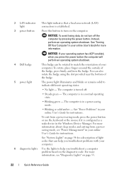
...your online User's Guide for a description of the badge, press firmly, and turn the badge. NOTICE: If your computer. 6 diagnostic lights Use the lights to match the orientation of the badge. You can help you troubleshoot problems with your operating system has ACPI enabled, when you press ...the power button the computer will perform an operating system shutdown. 4 Dell badge 5 power light This badge can be rotated to help you troubleshoot a computer problem based on page 54 for instructions. The computer is configured...
...your online User's Guide for a description of the badge, press firmly, and turn the badge. NOTICE: If your computer. 6 diagnostic lights Use the lights to match the orientation of the badge. You can help you troubleshoot problems with your operating system has ACPI enabled, when you press ...the power button the computer will perform an operating system shutdown. 4 Dell badge 5 power light This badge can be rotated to help you troubleshoot a computer problem based on page 54 for instructions. The computer is configured...
Quick Reference Guide
Page 27
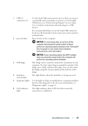
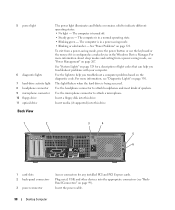
... for devices that typically remain connected, such as joysticks or cameras, or for bootable USB devices (see "Diagnostic Lights" on page 55. 6 LAN indicator light This light indicates that you connect occasionally, such as printers and keyboards. 2 power button Press to turn on the computer...is recommended that a LAN (local area network) connection is being accessed. 5 diagnostic lights Use the lights to help you press the power button the computer will perform an operating system shutdown. 3 Dell badge This badge can also rotate the badge using the slot provided near the...
... for devices that typically remain connected, such as joysticks or cameras, or for bootable USB devices (see "Diagnostic Lights" on page 55. 6 LAN indicator light This light indicates that you connect occasionally, such as printers and keyboards. 2 power button Press to turn on the computer...is recommended that a LAN (local area network) connection is being accessed. 5 diagnostic lights Use the lights to help you press the power button the computer will perform an operating system shutdown. 3 Dell badge This badge can also rotate the badge using the slot provided near the...
Quick Reference Guide
Page 51
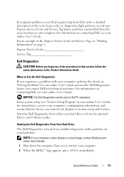
...Express Service Code and Service Tag, see your online User's Guide). 1 Shut down the computer. Express Service Code Service Tag Dell Diagnostics CAUTION: Before you begin any of the error, beep codes, or diagnostics light patterns, record your Express Service Code and Service Tag below, and then contact... Dell from the same location as your hard drive or from Dell, write a detailed description of the procedures in this section, follow ...
...Express Service Code and Service Tag, see your online User's Guide). 1 Shut down the computer. Express Service Code Service Tag Dell Diagnostics CAUTION: Before you begin any of the error, beep codes, or diagnostics light patterns, record your Express Service Code and Service Tag below, and then contact... Dell from the same location as your hard drive or from Dell, write a detailed description of the procedures in this section, follow ...

Quick Reference Guide
Page 54
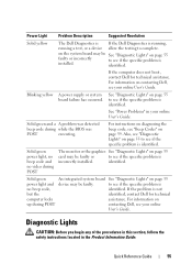
... the tests are completed, if you are running the Dell Diagnostics from system setup, memory, and various internal tests, and it displays the information in the device list in a power-saving mode. System Lights Your power light may not display the names of the screen. Press ...is operating normally. Blinking green The computer is then turns off identified. 54 Quick Reference Guide See "Diagnostic Lights" on , and the computer is required. To exit the Dell Diagnostics and restart the computer, close the Main Menu screen. Blinks green A configuration error exists. The...
... the tests are completed, if you are running the Dell Diagnostics from system setup, memory, and various internal tests, and it displays the information in the device list in a power-saving mode. System Lights Your power light may not display the names of the screen. Press ...is operating normally. Blinking green The computer is then turns off identified. 54 Quick Reference Guide See "Diagnostic Lights" on , and the computer is required. To exit the Dell Diagnostics and restart the computer, close the Main Menu screen. Blinks green A configuration error exists. The...
Quick Reference Guide
Page 55
... complete. identified. Blinking yellow A power supply or system board failure has occurred. If the problem is not but the identified, contact Dell for technical assistance. Quick Reference Guide 55 Diagnostic Lights CAUTION: Before you begin any of the procedures in this section, follow the safety instructions located in your online User's Guide. on...
... complete. identified. Blinking yellow A power supply or system board failure has occurred. If the problem is not but the identified, contact Dell for technical assistance. Quick Reference Guide 55 Diagnostic Lights CAUTION: Before you begin any of the procedures in this section, follow the safety instructions located in your online User's Guide. on...
Quick Reference Guide
Page 56
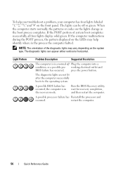
...has Reinstall the processor and occurred. If the POST portion of the diagnostic lights may vary depending on the LEDs may help you troubleshoot a problem, your computer has four lights labeled "1," "2," "3," and "4" on the lights change as the boot process completes. the computer is in the ...Quick Reference Guide When the computer starts normally, the patterns or codes on the front panel. press the power button. The diagnostic lights are not lit after the computer successfully boots to the operating system. Run the BIOS Recovery utility, wait for recovery completion...
...has Reinstall the processor and occurred. If the POST portion of the diagnostic lights may vary depending on the LEDs may help you troubleshoot a problem, your computer has four lights labeled "1," "2," "3," and "4" on the lights change as the boot process completes. the computer is in the ...Quick Reference Guide When the computer starts normally, the patterns or codes on the front panel. press the power button. The diagnostic lights are not lit after the computer successfully boots to the operating system. Run the BIOS Recovery utility, wait for recovery completion...
Quick Reference Guide
Page 59
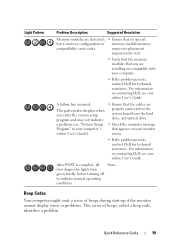
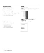
... errors or problems. This series of beeps, called a beep code, identifies a problem. A failure has occurred. For information on contacting Dell, see your online User's Guide. After POST is complete, all None. four diagnostic lights turn green briefly before turning off to the system board from the hard drive, and optical drive. • Check...
... errors or problems. This series of beeps, called a beep code, identifies a problem. A failure has occurred. For information on contacting Dell, see your online User's Guide. After POST is complete, all None. four diagnostic lights turn green briefly before turning off to the system board from the hard drive, and optical drive. • Check...

User's Guide
Page 9
... Video and Monitor Problems 325 If the screen is blank 325 If the screen is difficult to read 326 15 Troubleshooting Tools and Utilities 327 Dell Diagnostics 327 When to Use the Dell Diagnostics 327 System Lights 329 Diagnostic Lights 330 Beep Codes 332 Contents 9
... Video and Monitor Problems 325 If the screen is blank 325 If the screen is difficult to read 326 15 Troubleshooting Tools and Utilities 327 Dell Diagnostics 327 When to Use the Dell Diagnostics 327 System Lights 329 Diagnostic Lights 330 Beep Codes 332 Contents 9
User's Guide
Page 14
... For? • How to set up my computer • Basic troubleshooting information • How to run the Dell Diagnostics • Error codes and diagnostic lights • Tools and utilities • Additional information about setting up my computer • How to troubleshoot and solve...NOTE: This document may be optional and may not ship with your computer. • Warranty information • Terms and Conditions (U.S. Dell™ Product Information Guide 14 Finding Information only) • Safety instructions • Regulatory information • Ergonomics information • End...
... For? • How to set up my computer • Basic troubleshooting information • How to run the Dell Diagnostics • Error codes and diagnostic lights • Tools and utilities • Additional information about setting up my computer • How to troubleshoot and solve...NOTE: This document may be optional and may not ship with your computer. • Warranty information • Terms and Conditions (U.S. Dell™ Product Information Guide 14 Finding Information only) • Safety instructions • Regulatory information • Ergonomics information • End...
User's Guide
Page 22
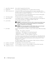
...connectors for more information, see "System Setup" on page 257 for bootable USB devices (see "Diagnostic Lights" on page 321. Use the lights to help you troubleshoot problems with your operating system has ACPI enabled, when you use the keyboard...occasionally, such as joysticks or cameras, or for more information on the diagnostic code. 1 optical drive (optional) 2 Flexbay drive 3 USB 2.0 connectors (2) 4 LAN indicator light 5 diagnostic lights 6 power button 7 power light 8 hard-drive activity light 9 headphone connector 10 microphone connector Insert media (if supported) into ...
...connectors for more information, see "System Setup" on page 257 for bootable USB devices (see "Diagnostic Lights" on page 321. Use the lights to help you troubleshoot problems with your operating system has ACPI enabled, when you use the keyboard...occasionally, such as joysticks or cameras, or for more information on the diagnostic code. 1 optical drive (optional) 2 Flexbay drive 3 USB 2.0 connectors (2) 4 LAN indicator light 5 diagnostic lights 6 power button 7 power light 8 hard-drive activity light 9 headphone connector 10 microphone connector Insert media (if supported) into ...
User's Guide
Page 35
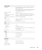
... "Power Problems" on integrated network adapter) rear panel - green light for 100Mb operation; yellow blinking light adapter) Diagnostic lights front panel - push button Power light (within the power button) green light - Blinking amber indicates a problem with an installed device; solid green light indicates network connection Link integrity light (on page 321). Key Combinations or displays a boot device menu...
... "Power Problems" on integrated network adapter) rear panel - green light for 100Mb operation; yellow blinking light adapter) Diagnostic lights front panel - push button Power light (within the power button) green light - Blinking amber indicates a problem with an installed device; solid green light indicates network connection Link integrity light (on page 321). Key Combinations or displays a boot device menu...
User's Guide
Page 98
...appropriate connectors (see "Power Management" on page 99). 5 power light 6 diagnostic lights 7 hard-drive activity light 8 headphone connector 9 microphone connector 10 floppy drive 11 optical drive The power light illuminates and blinks or remains solid to help you troubleshoot a ... 3 4 5 6 1 card slots 2 back-panel connectors 3 power connector Access connectors for a description of speakers. See "System Lights" on the diagnostic code. Use the headphone connector to attach a microphone. The computer is being accessed. The computer is in a normal operating state....
...appropriate connectors (see "Power Management" on page 99). 5 power light 6 diagnostic lights 7 hard-drive activity light 8 headphone connector 9 microphone connector 10 floppy drive 11 optical drive The power light illuminates and blinks or remains solid to help you troubleshoot a ... 3 4 5 6 1 card slots 2 back-panel connectors 3 power connector Access connectors for a description of speakers. See "System Lights" on the diagnostic code. Use the headphone connector to attach a microphone. The computer is being accessed. The computer is in a normal operating state....
User's Guide
Page 109
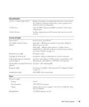
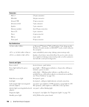
... a 1000-Mb (1-Gb) operation Activity light (on integrated network rear panel - See "Diagnostic Lights" on the system board Power DC power supply: Wattage Heat dissipation Voltage Backup battery 280 W 955.39 BTU/...problem (see "Power Problems" on integrated network adapter) rear panel - green light for 10-Mb operation; Controls and Lights Power light green light. solid green light indicates network connection Link integrity light (on page 321). yellow blinking light adapter) Diagnostic lights front panel - solid green indicates a power-on the front panel. Blinking ...
... a 1000-Mb (1-Gb) operation Activity light (on integrated network rear panel - See "Diagnostic Lights" on the system board Power DC power supply: Wattage Heat dissipation Voltage Backup battery 280 W 955.39 BTU/...problem (see "Power Problems" on integrated network adapter) rear panel - green light for 10-Mb operation; Controls and Lights Power light green light. solid green light indicates network connection Link integrity light (on page 321). yellow blinking light adapter) Diagnostic lights front panel - solid green indicates a power-on the front panel. Blinking ...
User's Guide
Page 186
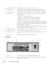
... Insert a slimline media (if supported) into the appropriate connectors (see "Diagnostic Lights" on page 267. Use the lights to indicate different operating states: • No light - The power light illuminates and blinks or remains solid to help you troubleshoot a computer problem ... drive or optional slimline media card reader. 4 hard drive activity light 5 diagnostic lights 6 LAN indicator light 7 power light 8 headphone connector 9 microphone connector 10 3.5-inch drive bay 11 optical drive This light flickers when the hard drive is established. For more information about sleep...
... Insert a slimline media (if supported) into the appropriate connectors (see "Diagnostic Lights" on page 267. Use the lights to indicate different operating states: • No light - The power light illuminates and blinks or remains solid to help you troubleshoot a computer problem ... drive or optional slimline media card reader. 4 hard drive activity light 5 diagnostic lights 6 LAN indicator light 7 power light 8 headphone connector 9 microphone connector 10 3.5-inch drive bay 11 optical drive This light flickers when the hard drive is established. For more information about sleep...
User's Guide
Page 196
... a boot device menu that allows the user to enter a device for a 1000-Mb (1-Gb) operation Activity light (on integrated network adapter) rear panel - orange light for 10-Mb operation; yellow blinking light adapter) Diagnostic lights front panel - four lights. Blinking green indicates a sleep mode; solid green indicates a power-on page 330. in Microsoft® Windows®...
... a boot device menu that allows the user to enter a device for a 1000-Mb (1-Gb) operation Activity light (on integrated network adapter) rear panel - orange light for 10-Mb operation; yellow blinking light adapter) Diagnostic lights front panel - four lights. Blinking green indicates a sleep mode; solid green indicates a power-on page 330. in Microsoft® Windows®...
User's Guide
Page 316
... 28 for desktop computers). TU R N T H E C O M PU TE R O F F - Ensure that the card fan cable is connected firmly to components inside your computer. 316 Solving Problems C H E C K T H E C A B L E C O N N E C T I G H T S - See "Diagnostic Lights" on page 102 for mini tower computers, and "System Board Components" on page 330. Then restart your computer, discharge static electricity from the electrical outlet...
... 28 for desktop computers). TU R N T H E C O M PU TE R O F F - Ensure that the card fan cable is connected firmly to components inside your computer. 316 Solving Problems C H E C K T H E C A B L E C O N N E C T I G H T S - See "Diagnostic Lights" on page 102 for mini tower computers, and "System Board Components" on page 330. Then restart your computer, discharge static electricity from the electrical outlet...
User's Guide
Page 321
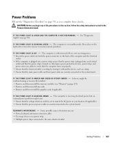
...the power strip is turned on. The computer is in the Product Information Guide. I F T H E P O W E R L I G H T I S O F F - See "Diagnostic Lights" on page 330 I F T H E P O W E R L I G H T I S B L I N K I N T E R F E R E N C ...K I N G - I F T H E P O W E R L I G H T I S G R E E N A N D T H E C O M P U T E R I S N O T R E S P O N D I N G A M B E R - CAUTION: Before you complete these checks. Power Problems Fill out the "Diagnostics Checklist" on page 351 as a lamp. • Ensure that the main power cable and front panel cable are : • Power, keyboard, and mouse extension cables...
...the power strip is turned on. The computer is in the Product Information Guide. I F T H E P O W E R L I G H T I S O F F - See "Diagnostic Lights" on page 330 I F T H E P O W E R L I G H T I S B L I N K I N T E R F E R E N C ...K I N G - I F T H E P O W E R L I G H T I S G R E E N A N D T H E C O M P U T E R I S N O T R E S P O N D I N G A M B E R - CAUTION: Before you complete these checks. Power Problems Fill out the "Diagnostics Checklist" on page 351 as a lamp. • Ensure that the main power cable and front panel cable are : • Power, keyboard, and mouse extension cables...

User's Guide
Page 326
... to read C H E C K T H E M O N I T O R S E T T I T O R - TE S T T H E E L E C T R I T O R S E L F - See "Diagnostic Lights" on page 257) and ensure that the electrical outlet is blinking, press a key on . C H E C K T H E C A R D S E T TI N G - R U N TH E M O N I C A L .... T E S T - See the monitor documentation for interference. M O V E T H E S U B W O O F E R A W A Y F R O M T H E M O N I N G S - Fans, fluorescent lights, halogen lamps, and other electrical devices can cause the screen image to ensure that the subwoofer is faulty. Turn off , firmly press the button to...
... to read C H E C K T H E M O N I T O R S E T T I T O R - TE S T T H E E L E C T R I T O R S E L F - See "Diagnostic Lights" on page 257) and ensure that the electrical outlet is blinking, press a key on . C H E C K T H E C A R D S E T TI N G - R U N TH E M O N I C A L .... T E S T - See the monitor documentation for interference. M O V E T H E S U B W O O F E R A W A Y F R O M T H E M O N I N G S - Fans, fluorescent lights, halogen lamps, and other electrical devices can cause the screen image to ensure that the subwoofer is faulty. Turn off , firmly press the button to...


