User Manual
Page 8
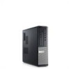
... indicates that the computer is turned on . The power supply is reading data from or writing data to the power connector (at support.dell.com/manuals. The power cable must be defective. Solid blue light indicates power-on the front panel of computer: Power button light Blue ... be connected to the hard drive. NOTE: You can test the health of the computer. Solid amber light when the computer does not start, indicates a problem with the system board. blinking blue light indicates sleep state of the power system by pressing the power-supply diagnostic button...
... indicates that the computer is turned on . The power supply is reading data from or writing data to the power connector (at support.dell.com/manuals. The power cable must be defective. Solid blue light indicates power-on the front panel of computer: Power button light Blue ... be connected to the hard drive. NOTE: You can test the health of the computer. Solid amber light when the computer does not start, indicates a problem with the system board. blinking blue light indicates sleep state of the power system by pressing the power-supply diagnostic button...

User Manual
Page 10
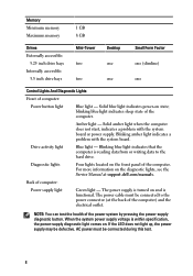
... Atom™, Centrino®, and Celeron® are trademarks of Dell Inc. AMD® is strictly forbidden. Microsoft®, Windows®, MS-DOS®, Windows Vista®, the Windows Vista start button, and 10 Environmental Temperature: Operating Storage Relative humidity Altitude: ... countries. only) • End User License Agreement Information in this text: Dell™, the DELL logo, Dell Precision™, Precision ON™, ExpressCharge™, Latitude™, Latitude ON™, OptiPlex™, Vostro™, and Wi-Fi Catcher™ are registered trademarks or ...
... Atom™, Centrino®, and Celeron® are trademarks of Dell Inc. AMD® is strictly forbidden. Microsoft®, Windows®, MS-DOS®, Windows Vista®, the Windows Vista start button, and 10 Environmental Temperature: Operating Storage Relative humidity Altitude: ... countries. only) • End User License Agreement Information in this text: Dell™, the DELL logo, Dell Precision™, Precision ON™, ExpressCharge™, Latitude™, Latitude ON™, OptiPlex™, Vostro™, and Wi-Fi Catcher™ are registered trademarks or ...
Technical Guide
Page 9
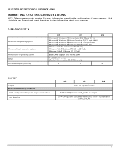
DELL™ OPTIPLEX™ 390 TECHNICAL GUIDEBOOK -FINAL MARKETING SYSTEM CONFIGURATIONS NOTE: Offerings may vary by country. For more information regarding the configuration of your computer, click Start>Help and Support and select the option to view information about your computer. OPERATING SYSTEM Windows 7® ... bits), Windows Vista® Business SP2 (32 and 64 bit), Windows Vista® Ultimate SP2 (32 bit) Basic Driver support only via Dell.com FreeDOS for (N-series), Ubuntu® Linux version 10.10 (China only) X X X CHIPSET Chipset Non-volatile memory on chipset BIOS ...
DELL™ OPTIPLEX™ 390 TECHNICAL GUIDEBOOK -FINAL MARKETING SYSTEM CONFIGURATIONS NOTE: Offerings may vary by country. For more information regarding the configuration of your computer, click Start>Help and Support and select the option to view information about your computer. OPERATING SYSTEM Windows 7® ... bits), Windows Vista® Business SP2 (32 and 64 bit), Windows Vista® Ultimate SP2 (32 bit) Basic Driver support only via Dell.com FreeDOS for (N-series), Ubuntu® Linux version 10.10 (China only) X X X CHIPSET Chipset Non-volatile memory on chipset BIOS ...
Owners Manual
Page 2
...™, Latitude ON™, OptiPlex™, Vostro™, and Wi-Fi Catcher™ are not followed. Blu-ray Disc™ is under license. Microsoft®, Windows®, MS-DOS®, Windows Vista®, the Windows Vista start button, and Office Outlook® are registered trademarks or trademarks of Dell Inc. Intel®, Pentium...
...™, Latitude ON™, OptiPlex™, Vostro™, and Wi-Fi Catcher™ are not followed. Blu-ray Disc™ is under license. Microsoft®, Windows®, MS-DOS®, Windows Vista®, the Windows Vista start button, and Office Outlook® are registered trademarks or trademarks of Dell Inc. Intel®, Pentium...

Owners Manual
Page 8
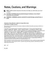
... steps before you work surface is unplugged to dissipate static electricity, which could harm internal components. Shut down the operating system: • In Windows 7: Click Start , then click Shut Down. • In Windows Vista: 8 Ensure that your computer and all network cables from being scratched. 2. Press and hold the power button...
... steps before you work surface is unplugged to dissipate static electricity, which could harm internal components. Shut down the operating system: • In Windows 7: Click Start , then click Shut Down. • In Windows Vista: 8 Ensure that your computer and all network cables from being scratched. 2. Press and hold the power button...
Owners Manual
Page 9
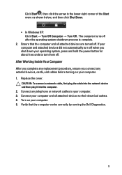
Ensure that the computer works correctly by running the Dell Diagnostics. 9 Verify that the computer and all attached devices to their electrical outlets. 4. If your computer and attached devices did not automatically turn off when ... the operating system shutdown process is complete. 2. After Working Inside Your Computer After you complete any telephone or network cables to turn them off . Click Start , then click the arrow in the lower-right corner of the Start menu as shown below, and then click Shut Down. • In Windows XP: Click...
Ensure that the computer works correctly by running the Dell Diagnostics. 9 Verify that the computer and all attached devices to their electrical outlets. 4. If your computer and attached devices did not automatically turn off when ... the operating system shutdown process is complete. 2. After Working Inside Your Computer After you complete any telephone or network cables to turn them off . Click Start , then click the arrow in the lower-right corner of the Start menu as shown below, and then click Shut Down. • In Windows XP: Click...
Owners Manual
Page 62
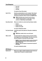
... powered on by default. This option is Disabled by a special LAN signal. This option is set to power up signal from the off your computer starts. Sets time to automatically turn off state when triggered by default.
... powered on by default. This option is Disabled by a special LAN signal. This option is set to power up signal from the off your computer starts. Sets time to automatically turn off state when triggered by default.
Owners Manual
Page 63
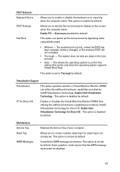
... from utilizing the additional hardware capabilities provided by default. Allows you to specify the function keys to display on the screen when the computer starts. This option is enabled by bypassing some compatibility steps: • Minimal - This option is not set by Intel® Virtualization technology ... system to Thorough by default. Allows you to enable or disable the keyboard error reporting when the computer starts. Enable Intel Virtualization Technology - This option is disabled by default. This option is disabled by Intel® Virtualization Technology.
... from utilizing the additional hardware capabilities provided by default. Allows you to specify the function keys to display on the screen when the computer starts. This option is enabled by bypassing some compatibility steps: • Minimal - This option is not set by Intel® Virtualization technology ... system to Thorough by default. Allows you to enable or disable the keyboard error reporting when the computer starts. Enable Intel Virtualization Technology - This option is disabled by default. This option is disabled by Intel® Virtualization Technology.

Owners Manual
Page 67
... the chassis next to stop. NOTE: The diagnostic lights will not blink when it with the system easier and more accurate. Once the operating system starts to help identifying a possible problem with another device, such as an indicator of the progress through the Power-on the front of the computer and...
... the chassis next to stop. NOTE: The diagnostic lights will not blink when it with the system easier and more accurate. Once the operating system starts to help identifying a possible problem with another device, such as an indicator of the progress through the Power-on the front of the computer and...
Owners Manual
Page 69
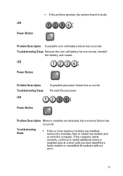
...-install one at a time) until you have identified a faulty module or reinstalled all peripheral cards from the PCI and PCI-E slots and re-start the computer. Troubleshooting Steps The computer hardware is installed, try moving it to install additional memory modules (one module and re...-start the computer. • If available, install verified working memory of the same type into your computer. LED Power Button Problem Description BIOS ...
...-install one at a time) until you have identified a faulty module or reinstalled all peripheral cards from the PCI and PCI-E slots and re-start the computer. Troubleshooting Steps The computer hardware is installed, try moving it to install additional memory modules (one module and re...-start the computer. • If available, install verified working memory of the same type into your computer. LED Power Button Problem Description BIOS ...

Owners Manual
Page 70
... you find the bad one. Troubleshooting Steps Re-seat the 2x2 power connector from the PCI and PCI-E slots and re-start the computer. LED Power Button Problem Description Troubleshooting Steps Possible peripheral card or system board failure has occurred. Remove all internal and... external peripherals, and re-start the computer. LED Power Button add the peripheral cards back one by one until you find the bad one. Problem Description Power...
... you find the bad one. Troubleshooting Steps Re-seat the 2x2 power connector from the PCI and PCI-E slots and re-start the computer. LED Power Button Problem Description Troubleshooting Steps Possible peripheral card or system board failure has occurred. Remove all internal and... external peripherals, and re-start the computer. LED Power Button add the peripheral cards back one by one until you find the bad one. Problem Description Power...
Owners Manual
Page 71
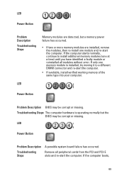
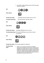
If the computer starts normally, continue to install additional memory modules (one minute, reinstall the battery, and restart. Problem Description A possible coin cell battery failure has occurred. Troubleshooting Steps ... are detected, but a memory failure has occurred. Power Button Problem Description Memory modules are installed, remove the modules, then re-install one module and re-start the computer. LED Power Button Problem Description Troubleshooting Steps LED A possible processor failure has occurred. Re-seat the processor. LED Power Button • If the...
If the computer starts normally, continue to install additional memory modules (one minute, reinstall the battery, and restart. Problem Description A possible coin cell battery failure has occurred. Troubleshooting Steps ... are detected, but a memory failure has occurred. Power Button Problem Description Memory modules are installed, remove the modules, then re-install one module and re-start the computer. LED Power Button Problem Description Troubleshooting Steps LED A possible processor failure has occurred. Re-seat the processor. LED Power Button • If the...
Owners Manual
Page 72
... Description A possible USB failure has occurred. LED Power Button Problem Description No memory modules are installed, remove the modules (see your computer. If the computer starts normally, continue to install additional memory modules (one module (see your service manual), then reinstall one at a time) until you have identified a faulty module or...
... Description A possible USB failure has occurred. LED Power Button Problem Description No memory modules are installed, remove the modules (see your computer. If the computer starts normally, continue to install additional memory modules (one module (see your service manual), then reinstall one at a time) until you have identified a faulty module or...
Owners Manual
Page 73
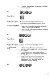
... you are detected, but a memory configuration or compatibility error has occurred. LED Power Button Problem Description A possible expansion card failure has occurred. If the computer starts normally, troubleshoot the last card removed from the computer for resource conflicts. LED 73
... you are detected, but a memory configuration or compatibility error has occurred. LED Power Button Problem Description A possible expansion card failure has occurred. If the computer starts normally, troubleshoot the last card removed from the computer for resource conflicts. LED 73
Owners Manual
Page 74
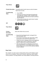
Beep Codes The computer can emit a series of beeps during start-up if the display cannot show errors or problems. These series of beeps, called beep codes, identify various problems. The delay between 74 Troubleshooting Steps &#...
Beep Codes The computer can emit a series of beeps during start-up if the display cannot show errors or problems. These series of beeps, called beep codes, identify various problems. The delay between 74 Troubleshooting Steps &#...

Owners Manual
Page 81
For more information regarding the configuration of your computer, click Start (or Start in Windows XP) Help and Support, and then select the option to 8 MB cache depending on processor type Memory Type Speed Connectors Capacity Minimum Memory ...
For more information regarding the configuration of your computer, click Start (or Start in Windows XP) Help and Support, and then select the option to 8 MB cache depending on processor type Memory Type Speed Connectors Capacity Minimum Memory ...
Owners Manual
Page 85
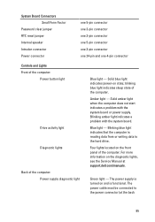
... Lights Front of the computer: Power button light Drive activity light Diagnostic lights Back of the computer. Solid amber light when the computer does not start indicates a problem with the system board. The power supply is reading data from or writing data to the power connector (at support....dell.com/manuals. Blinking amber light indicates a problem with the system board or power supply. The power cable must be connected to the hard drive. blinking ...
... Lights Front of the computer: Power button light Drive activity light Diagnostic lights Back of the computer. Solid amber light when the computer does not start indicates a problem with the system board. The power supply is reading data from or writing data to the power connector (at support....dell.com/manuals. Blinking amber light indicates a problem with the system board or power supply. The power cable must be connected to the hard drive. blinking ...


