User Manual
Page 1
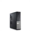
... :D12M, D07D, D04S Regulatory Type :D12M001, D07D001, D04S001 2011 - 05 headphone connector 4. power-supply diagnostic light 11. Front And Back View Of Mini-Tower 1. optical drive eject button 8. Mini-Tower - diagnostic lights (4) 6. Front And Back View Figure 1. Dell Optiplex 390 Setup And Features Information About Warnings WARNING: A WARNING indicates a potential for property damage, personal injury...
... :D12M, D07D, D04S Regulatory Type :D12M001, D07D001, D04S001 2011 - 05 headphone connector 4. power-supply diagnostic light 11. Front And Back View Of Mini-Tower 1. optical drive eject button 8. Mini-Tower - diagnostic lights (4) 6. Front And Back View Figure 1. Dell Optiplex 390 Setup And Features Information About Warnings WARNING: A WARNING indicates a potential for property damage, personal injury...
User Manual
Page 2
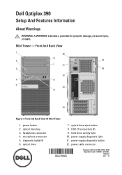
13. security cable slot 16. optical drive eject button 3. power button 4. headphone connector 7. padlock ring 10. Front And Back View Of Desktop 1. USB 2.0 connectors (2) 5. expansion card slots (4) 14. power-supply diagnostic light 15. power-supply diagnostic button 2 microphone connector 6. expansion card slots (4) Desktop - optical drive 2. diagnostic lights (4) 9. Front And Back View 15. power cable connector 12. hard-drive activity light 8. back panel connectors 13. back panel connectors 14. security cable slot 11. padlock ring Figure 2.
13. security cable slot 16. optical drive eject button 3. power button 4. headphone connector 7. padlock ring 10. Front And Back View Of Desktop 1. USB 2.0 connectors (2) 5. expansion card slots (4) 14. power-supply diagnostic light 15. power-supply diagnostic button 2 microphone connector 6. expansion card slots (4) Desktop - optical drive 2. diagnostic lights (4) 9. Front And Back View 15. power cable connector 12. hard-drive activity light 8. back panel connectors 13. back panel connectors 14. security cable slot 11. padlock ring Figure 2.
User Manual
Page 3
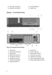
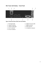
Back Panel Figure 3. line-in connector 5. line-out connector 6. microphone connector 3 Back Panel View of Mini-Tower And Desktop 1. link integrity light 2. network connector 3. Mini-Tower And Desktop - network activity light 4. VGA connector 9. HDMI connector 8. USB 2.0 connectors (6) 7.
Back Panel Figure 3. line-in connector 5. line-out connector 6. microphone connector 3 Back Panel View of Mini-Tower And Desktop 1. link integrity light 2. network connector 3. Mini-Tower And Desktop - network activity light 4. VGA connector 9. HDMI connector 8. USB 2.0 connectors (6) 7.
User Manual
Page 4
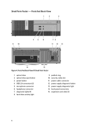
Front And Back View Of Small Form Factor 1. diagnostic lights (4) 8. security cable slot 11. power button 4. hard-drive activity light 9. power cable connector 12. optical drive 2. back panel connectors 15. USB 2.0 connectors (2) 5. padlock ring 10. power-supply diagnostic light 14. expansion card slots (2) 4 headphone connector 7. microphone connector 6. power-supply diagnostic button 13. Front And Back View Figure 4. optical drive eject button 3. Small Form Factor -
Front And Back View Of Small Form Factor 1. diagnostic lights (4) 8. security cable slot 11. power button 4. hard-drive activity light 9. power cable connector 12. optical drive 2. back panel connectors 15. USB 2.0 connectors (2) 5. padlock ring 10. power-supply diagnostic light 14. expansion card slots (2) 4 headphone connector 7. microphone connector 6. power-supply diagnostic button 13. Front And Back View Figure 4. optical drive eject button 3. Small Form Factor -

User Manual
Page 5
network connector 3. line-out connector 5. Back Panel View of the following cables: Figure 6. network activity light 4. VGA connector 7. HDMI Connector 5 link integrity light 2. NOTE: Some devices may not be included if you begin any of the procedures in /microphone connector Quick Setup WARNING: ... 8. Back Panel Figure 5. line-in this section, read the safety information that shipped with your computer. For additional best practices information, see www.dell.com/regulatory_compliance. Small Form Factor - Connect the monitor using only one of Small Form Factor 1.
network connector 3. line-out connector 5. Back Panel View of the following cables: Figure 6. network activity light 4. VGA connector 7. HDMI Connector 5 link integrity light 2. NOTE: Some devices may not be included if you begin any of the procedures in /microphone connector Quick Setup WARNING: ... 8. Back Panel Figure 5. line-in this section, read the safety information that shipped with your computer. For additional best practices information, see www.dell.com/regulatory_compliance. Small Form Factor - Connect the monitor using only one of Small Form Factor 1.
User Manual
Page 8
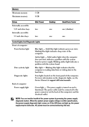
..., the power supply may be connected during this test. 8 The power cable must be defective. Amber light - Blinking blue light indicates that the computer is reading data from or writing data to the power connector (at support.dell.com/manuals. Memory Minimum memory Maximum memory 1 GB 8 GB Drives Externally accessible: 5.25 inch drive...
..., the power supply may be connected during this test. 8 The power cable must be defective. Amber light - Blinking blue light indicates that the computer is reading data from or writing data to the power connector (at support.dell.com/manuals. Memory Minimum memory Maximum memory 1 GB 8 GB Drives Externally accessible: 5.25 inch drive...
Technical Guide
Page 3
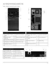
DELL™ OPTIPLEX™ 390 TECHNICAL GUIDEBOOK -FINAL MINI TOWER COMPUTER (MT) VIEW 1 6 10 7 11 15 2 12 16 8 3 4 9 5 13 14 FRONT VIEW BACK VIEW 1 Power Button, Power Light 6 Optical Drive (optional) 2 Optical Drive Bay (optional) 7 Optical Drive Eject Button 3 Microphone Connector 8 USB 2.0 Connectors (2) 4 Headphone Connector 9 Drive Activity Light 10 Power Supply Diagnostic 14 Expansion Card Slots...
DELL™ OPTIPLEX™ 390 TECHNICAL GUIDEBOOK -FINAL MINI TOWER COMPUTER (MT) VIEW 1 6 10 7 11 15 2 12 16 8 3 4 9 5 13 14 FRONT VIEW BACK VIEW 1 Power Button, Power Light 6 Optical Drive (optional) 2 Optical Drive Bay (optional) 7 Optical Drive Eject Button 3 Microphone Connector 8 USB 2.0 Connectors (2) 4 Headphone Connector 9 Drive Activity Light 10 Power Supply Diagnostic 14 Expansion Card Slots...
Technical Guide
Page 5
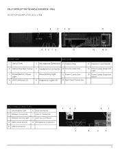
DELL™ OPTIPLEX™ 390 TECHNICAL GUIDEBOOK -FINAL DESKTOP COMPUTER (DT) VIEW 1 2 3 9 10 11 4 56 7 8 12 13 14 15 FRONT VIEW 1 Optical Drive BACK VIEW 5 Microphone Connector 9 Padlock Ring 13 Expansion Card Slots(4) 2 Optical Drive Eject Button 6 Headphone Connector 10 Security Cable Slot 3 Power Button, Power Light 4 USB Connectors (2) 7 Drive Activity Light 8 Diagnostic Lights (4) 11 Power Connectors...
DELL™ OPTIPLEX™ 390 TECHNICAL GUIDEBOOK -FINAL DESKTOP COMPUTER (DT) VIEW 1 2 3 9 10 11 4 56 7 8 12 13 14 15 FRONT VIEW 1 Optical Drive BACK VIEW 5 Microphone Connector 9 Padlock Ring 13 Expansion Card Slots(4) 2 Optical Drive Eject Button 6 Headphone Connector 10 Security Cable Slot 3 Power Button, Power Light 4 USB Connectors (2) 7 Drive Activity Light 8 Diagnostic Lights (4) 11 Power Connectors...
Technical Guide
Page 7
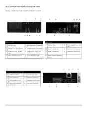
DELL™ OPTIPLEX™ 390 TECHNICAL GUIDEBOOK -FINAL SMALL FORM FACTOR COMPUTER (SFF) VIEW 1 2 3 9 10 11 12 13 4 56 7 8 14 15 FRONT VIEW 1 Optical Drive 5 Microphone Connector 2 Optical Drive Eject Button 6 Headphone Connector 3 Power Button, Power Light 4 USB 2.0 Connectors (2) 7 Diagnostic Lights (4) 8 Drive Activity Light BACK VIEW 9 Padlock Ring 10 Security Cable Slot 11 Power Connectors 13 Power...
DELL™ OPTIPLEX™ 390 TECHNICAL GUIDEBOOK -FINAL SMALL FORM FACTOR COMPUTER (SFF) VIEW 1 2 3 9 10 11 12 13 4 56 7 8 14 15 FRONT VIEW 1 Optical Drive 5 Microphone Connector 2 Optical Drive Eject Button 6 Headphone Connector 3 Power Button, Power Light 4 USB 2.0 Connectors (2) 7 Diagnostic Lights (4) 8 Drive Activity Light BACK VIEW 9 Padlock Ring 10 Security Cable Slot 11 Power Connectors 13 Power...
Owners Manual
Page 56
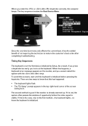
... that this is the case, rely on the monitor, and you cannot restart the system with the keys. If this has happened: • The keyboard lights flash. • The "F2=Setup" prompt appears in the top right-hand corner of the screen during boot. The second method is good if the... is visible. Timing Key Sequences The keyboard is already warmed up. To avoid this happens, a keyboard error message appears on the first method-the keyboard lights-to know the keyboard is initialized. 56
... that this is the case, rely on the monitor, and you cannot restart the system with the keys. If this has happened: • The keyboard lights flash. • The "F2=Setup" prompt appears in the top right-hand corner of the screen during boot. The second method is good if the... is visible. Timing Key Sequences The keyboard is already warmed up. To avoid this happens, a keyboard error message appears on the first method-the keyboard lights-to know the keyboard is initialized. 56

Owners Manual
Page 67
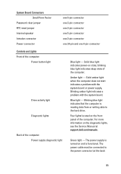
... the electrical outlet is not receiving power. • Re-seat the power cable in an attempt to the power button. NOTE: The diagnostic lights will not blink when it with the system easier and more accurate. The system now includes pre-POST and POST LEDs in the power connector... another device, such as an indicator of the progress through the Power-on Self-Test (POST) process. This has no longer visible. Diagnostic Light Patterns LED Power Button Problem Description Troubleshooting Steps The computer is either turned off or is working by testing it is blue. These LEDs do...
... the electrical outlet is not receiving power. • Re-seat the power cable in an attempt to the power button. NOTE: The diagnostic lights will not blink when it with the system easier and more accurate. The system now includes pre-POST and POST LEDs in the power connector... another device, such as an indicator of the progress through the Power-on Self-Test (POST) process. This has no longer visible. Diagnostic Light Patterns LED Power Button Problem Description Troubleshooting Steps The computer is either turned off or is working by testing it is blue. These LEDs do...
Owners Manual
Page 85
... is reading data from or writing data to the power connector (at support.dell.com/manuals. The power supply is turned on the front panel of the computer: Power supply diagnostic light Blue light - Solid blue light indicates power-on the diagnostic lights, see the Service Manual at the back 85 For more information on...
... is reading data from or writing data to the power connector (at support.dell.com/manuals. The power supply is turned on the front panel of the computer: Power supply diagnostic light Blue light - Solid blue light indicates power-on the diagnostic lights, see the Service Manual at the back 85 For more information on...
Owners Manual
Page 86
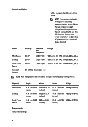
If the LED does not light up . Physical Mini-Tower Desktop Small Form Factor Height Width 36.00 cm (14.17 17.50 cm (6.89 inches) inches) 36.00 cm (14.... Hz, 4.4 A 100 VAC to 240 VAC, 50 Hz to 60 Hz, 3.6 A; 3 V CR2032 lithium coin cell NOTE: Heat dissipation is within specification, the self-test LED lights up , the power supply may be connected during this test. When the system power supply voltage is calculated by pressing the test button. NOTE: You...
If the LED does not light up . Physical Mini-Tower Desktop Small Form Factor Height Width 36.00 cm (14.17 17.50 cm (6.89 inches) inches) 36.00 cm (14.... Hz, 4.4 A 100 VAC to 240 VAC, 50 Hz to 60 Hz, 3.6 A; 3 V CR2032 lithium coin cell NOTE: Heat dissipation is within specification, the self-test LED lights up , the power supply may be connected during this test. When the system power supply voltage is calculated by pressing the test button. NOTE: You...


