Quick Reference
Page 8
..., and software updates 8 Quick Reference Guide Contact information, service call status and support history, service contract, online discussions with other Dell customers • Upgrades - Service call and order status, warranty, and repair information • Service and support - asked questions...; Community - Proactive e-mail notification of software and hardware updates for components, such as memory, the hard drive, and the operating system • Customer Care - support.dell.com and tips, articles from technicians, NOTE: Select your computer • Reference -...
..., and software updates 8 Quick Reference Guide Contact information, service call status and support history, service contract, online discussions with other Dell customers • Upgrades - Service call and order status, warranty, and repair information • Service and support - asked questions...; Community - Proactive e-mail notification of software and hardware updates for components, such as memory, the hard drive, and the operating system • Customer Care - support.dell.com and tips, articles from technicians, NOTE: Select your computer • Reference -...
Quick Reference
Page 36
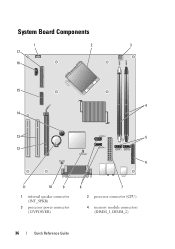
System Board Components 1 17 16 2 3 15 4 14 13 5 12 6 11 10 9 1 internal speaker connector (INT_SPKR) 3 processor power connector (12VPOWER) 8 7 2 processor connector (CPU) 4 memory module connectors (DIMM_1, DIMM_2) 36 Quick Reference Guide
System Board Components 1 17 16 2 3 15 4 14 13 5 12 6 11 10 9 1 internal speaker connector (INT_SPKR) 3 processor power connector (12VPOWER) 8 7 2 processor connector (CPU) 4 memory module connectors (DIMM_1, DIMM_2) 36 Quick Reference Guide
Quick Reference
Page 46
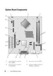
System Board Components 1 17 16 2 3 15 4 14 13 5 12 6 11 10 9 1 internal speaker connector (INT_SPKR) 3 processor power connector (12VPOWER) 8 7 2 processor connector (CPU) 4 memory module connectors (DIMM_1, DIMM_2) 46 Quick Reference Guide
System Board Components 1 17 16 2 3 15 4 14 13 5 12 6 11 10 9 1 internal speaker connector (INT_SPKR) 3 processor power connector (12VPOWER) 8 7 2 processor connector (CPU) 4 memory module connectors (DIMM_1, DIMM_2) 46 Quick Reference Guide

Quick Reference
Page 50
...test from the Custom Test or Symptom Tree option, click the applicable tab described in the computer. Option Test Memory Test System Exit Function Run the stand-alone memory test Run System Diagnostics Exit the Diagnostics 2 After you have selected the Test System option from the menu .... 50 Quick Reference Guide Write down the error code and problem description and contact Dell. If you contact Dell, technical support will ask for the option you want. Dell Diagnostics Main Menu 1 After the Dell Diagnostics loads and the Main Menu screen appears, click the button for your Service ...
...test from the Custom Test or Symptom Tree option, click the applicable tab described in the computer. Option Test Memory Test System Exit Function Run the stand-alone memory test Run System Diagnostics Exit the Diagnostics 2 After you have selected the Test System option from the menu .... 50 Quick Reference Guide Write down the error code and problem description and contact Dell. If you contact Dell, technical support will ask for the option you want. Dell Diagnostics Main Menu 1 After the Dell Diagnostics loads and the Main Menu screen appears, click the button for your Service ...
Quick Reference
Page 51
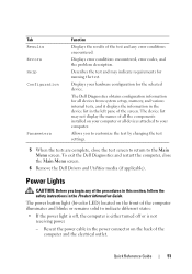
...changing the test settings. 5 When the tests are complete, close the Main Menu screen. 6 Remove the Dell Drivers and Utilities media (if applicable). The Dell Diagnostics obtains configuration information for the selected device. Allows you begin any error conditions encountered. Quick Reference Guide 51... and the electrical outlet. Displays your computer. To exit the Dell Diagnostics and restart the computer, close the test screen to return to your hardware configuration for all devices from system setup, memory, and various internal tests, and it displays the information in ...
...changing the test settings. 5 When the tests are complete, close the Main Menu screen. 6 Remove the Dell Drivers and Utilities media (if applicable). The Dell Diagnostics obtains configuration information for the selected device. Allows you begin any error conditions encountered. Quick Reference Guide 51... and the electrical outlet. Displays your computer. To exit the Dell Diagnostics and restart the computer, close the test screen to return to your hardware configuration for all devices from system setup, memory, and various internal tests, and it displays the information in ...

Quick Reference
Page 52
... power, but a device might be a power problem or an internal device malfunction. - Ensure that the power strip is not responding: - Remove and then reinstall the memory modules. - Remove and then reinstall any cards. - If the computer is plugged into a power strip, ensure that the power strip is plugged into an electrical...
... power, but a device might be a power problem or an internal device malfunction. - Ensure that the power strip is not responding: - Remove and then reinstall the memory modules. - Remove and then reinstall any cards. - If the computer is plugged into a power strip, ensure that the power strip is plugged into an electrical...
Quick Reference
Page 53
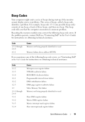
... the following beep code errors, see "Contacting Dell" in the User's Guide for instructions on obtaining technical assistance. Code 1-1-2 1-1-3 1-1-4 1-2-1 1-2-2 1-2-3 1-3 1-3-1 through 2-4-4 4-3-1 Cause Memory not being properly identified or used Memory failure above address 0FFFFh If you that the computer encountered a memory problem. If the problem persists, contact Dell (see "Contacting Dell" in the User's Guide) for instructions...
... the following beep code errors, see "Contacting Dell" in the User's Guide for instructions on obtaining technical assistance. Code 1-1-2 1-1-3 1-1-4 1-2-1 1-2-2 1-2-3 1-3 1-3-1 through 2-4-4 4-3-1 Cause Memory not being properly identified or used Memory failure above address 0FFFFh If you that the computer encountered a memory problem. If the problem persists, contact Dell (see "Contacting Dell" in the User's Guide) for instructions...
Quick Reference
Page 54
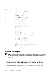
...test failure System Messages NOTE: If the message you received is not listed in protected mode Memory failure above address 0FFFFh Timer-chip counter 2 failure Time-of-day clock stopped Serial or parallel... 3-3-4 3-4-1 3-4-2 3-4-3 4-2-1 4-2-2 4-2-3 4-2-4 4-3-1 4-3-3 4-3-4 4-4-1 4-4-2 4-4-3 4-4-4 Cause Interrupt vector loading failure Keyboard Controller Test failure NVRAM power loss Invalid NVRAM configuration Video Memory Test failure Screen initialization failure Screen retrace failure Search for video ROM failure No timer tick Shutdown failure Gate A20 failure Unexpected interrupt in the...
...test failure System Messages NOTE: If the message you received is not listed in protected mode Memory failure above address 0FFFFh Timer-chip counter 2 failure Time-of-day clock stopped Serial or parallel... 3-3-4 3-4-1 3-4-2 3-4-3 4-2-1 4-2-2 4-2-3 4-2-4 4-3-1 4-3-3 4-3-4 4-4-1 4-4-2 4-4-3 4-4-4 Cause Interrupt vector loading failure Keyboard Controller Test failure NVRAM power loss Invalid NVRAM configuration Video Memory Test failure Screen initialization failure Screen retrace failure Search for video ROM failure No timer tick Shutdown failure Gate A20 failure Unexpected interrupt in the...
Quick Reference
Page 57
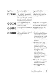
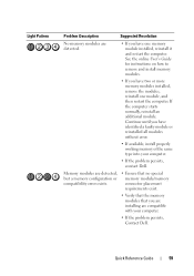
...The diagnostic lights are detected, but a memory failure has occurred. • If you...Memory modules are not lit after the computer successfully boots to remove and install memory... modules.) • If you have one module, and then restart the computer. press the power button. If the computer starts normally, reinstall an additional module. restart the computer. Continue until you have two or more memory... modules installed, remove the modules, reinstall one memory module installed,...memory of the same type into your computer. • If the problem persists...
...The diagnostic lights are detected, but a memory failure has occurred. • If you...Memory modules are not lit after the computer successfully boots to remove and install memory... modules.) • If you have one module, and then restart the computer. press the power button. If the computer starts normally, reinstall an additional module. restart the computer. Continue until you have two or more memory... modules installed, remove the modules, reinstall one memory module installed,...memory of the same type into your computer. • If the problem persists...
Quick Reference
Page 59
... your computer. • If the problem persists, Contact Dell. Continue until you have one module, and then restart the computer. Memory modules are detected, but a memory configuration or compatibility error exists. • Ensure that no special memory module/memory connector placement requirements exist. • Verify that the memory modules that you are installing are detected. •...
... your computer. • If the problem persists, Contact Dell. Continue until you have one module, and then restart the computer. Memory modules are detected, but a memory configuration or compatibility error exists. • Ensure that no special memory module/memory connector placement requirements exist. • Verify that the memory modules that you are installing are detected. •...

User's Guide
Page 7
IEEE 1394 Device Problems 119 Keyboard Problems 120 Lockups and Software Problems 120 Memory Problems 122 Mouse Problems 123 Network Problems 124 Power Problems 124 Printer Problems 125 Scanner Problems 126 Sound and Speaker Problems 127 Video... and Utilities 134 Troubleshooting Software and Hardware Problems . . 136 Restoring Your Operating System 137 Using Microsoft Windows System Restore . . . . 137 Using Dell™ PC Restore and Dell Factory Image Restore 139 Using the Operating System Media 142 11 Adding and Replacing Parts 143 Before You Begin 143 Recommended Tools 143...
IEEE 1394 Device Problems 119 Keyboard Problems 120 Lockups and Software Problems 120 Memory Problems 122 Mouse Problems 123 Network Problems 124 Power Problems 124 Printer Problems 125 Scanner Problems 126 Sound and Speaker Problems 127 Video... and Utilities 134 Troubleshooting Software and Hardware Problems . . 136 Restoring Your Operating System 137 Using Microsoft Windows System Restore . . . . 137 Using Dell™ PC Restore and Dell Factory Image Restore 139 Using the Operating System Media 142 11 Adding and Replacing Parts 143 Before You Begin 143 Recommended Tools 143...

User's Guide
Page 8
... the Computer Cover 147 Inside View of Your Computer 149 System Board Components 150 Power Supply DC Connector Pin Assignments . . . . . 152 Memory 155 Installation Guidelines 155 Installing Memory 156 Removing Memory 157 Cards 157 PCI and PCI Express Cards 158 Bezel 164 Removing the Bezel 165 Replacing the Bezel 166 Drives 166 Recommended...
... the Computer Cover 147 Inside View of Your Computer 149 System Board Components 150 Power Supply DC Connector Pin Assignments . . . . . 152 Memory 155 Installation Guidelines 155 Installing Memory 156 Removing Memory 157 Cards 157 PCI and PCI Express Cards 158 Bezel 164 Removing the Bezel 165 Replacing the Bezel 166 Drives 166 Recommended...
User's Guide
Page 9
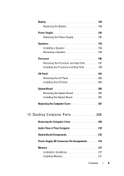
... Computer Parts 209 Removing the Computer Cover 209 Inside View of Your Computer 210 System Board Components 212 Power Supply DC Connector Pin Assignments . . . . . 214 Memory 217 Installation Guidelines 217 Installing...
... Computer Parts 209 Removing the Computer Cover 209 Inside View of Your Computer 210 System Board Components 212 Power Supply DC Connector Pin Assignments . . . . . 214 Memory 217 Installation Guidelines 217 Installing...

User's Guide
Page 10
Removing Memory 219 Cards 219 PCI and PCI Express Cards 220 Drives 226 Recommended Drive Cable Connections . . . . . 227 Connecting Drive Cables 227 Drive Interface Connectors 228 Connecting ...
Removing Memory 219 Cards 219 PCI and PCI Express Cards 220 Drives 226 Recommended Drive Cable Connections . . . . . 227 Connecting Drive Cables 227 Drive Interface Connectors 228 Connecting ...
User's Guide
Page 17
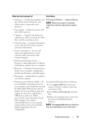
...Go. 3 Click your Service Tag. Contact information, service call status and support history, service contract, online discussions with other Dell customers Dell Support Website - DSS provides critical your operating system and search for processors, optical drives, USB devices, and so on. DSS...software updates • Desktop System Software (DSS) - and operating system and installs the NOTE: The support.dell.com user interface updates appropriate for components, such as memory, the hard drive, and the operating system • Customer Care - Find It Here • Solutions ...
...Go. 3 Click your Service Tag. Contact information, service call status and support history, service contract, online discussions with other Dell customers Dell Support Website - DSS provides critical your operating system and search for processors, optical drives, USB devices, and so on. DSS...software updates • Desktop System Software (DSS) - and operating system and installs the NOTE: The support.dell.com user interface updates appropriate for components, such as memory, the hard drive, and the operating system • Customer Care - Find It Here • Solutions ...
User's Guide
Page 27
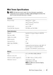
... Internal cache Front Side Bus frequency System Information Chipset Data bus width Address bus width DMA channels Interrupt levels BIOS chip (NVRAM) NIC Memory Type Memory connectors Memory modules supported Minimum memory Intel® Core™ 2 Duo Intel® Pentium® Dual Core Intel® Celeron® up to view information about your computer...
... Internal cache Front Side Bus frequency System Information Chipset Data bus width Address bus width DMA channels Interrupt levels BIOS chip (NVRAM) NIC Memory Type Memory connectors Memory modules supported Minimum memory Intel® Core™ 2 Duo Intel® Pentium® Dual Core Intel® Celeron® up to view information about your computer...
User's Guide
Page 28
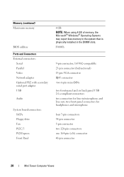
two front-panel connectors for line-in the DIMM slots. Memory (continued) Maximum memory BIOS address Ports and Connectors External connectors: Serial Parallel Video Network adapter Optional PS/2 with secondary serial port adapter USB Audio System board connectors: ...SATA Floppy drive Fan PCI 2.3 PCI Express Front Panel 4 GB NOTE: When using 4 GB of memory, the Microsoft® Windows® Operating Systems may report less memory in the system than is physically installed in /microphone and line-out; F0000h 9-pin connector; 16550C-compatible 25-pin connector...
two front-panel connectors for line-in the DIMM slots. Memory (continued) Maximum memory BIOS address Ports and Connectors External connectors: Serial Parallel Video Network adapter Optional PS/2 with secondary serial port adapter USB Audio System board connectors: ...SATA Floppy drive Fan PCI 2.3 PCI Express Front Panel 4 GB NOTE: When using 4 GB of memory, the Microsoft® Windows® Operating Systems may report less memory in the system than is physically installed in /microphone and line-out; F0000h 9-pin connector; 16550C-compatible 25-pin connector...
User's Guide
Page 39
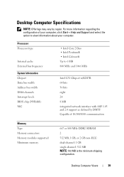
... ASF 1.03 and 2.0 support as defined by region. Desktop Computer Views 39 For more information regarding the configuration of 10/100/1000 communication Memory Type Memory connectors Memory modules supported Minimum memory 667 or 800 MHz DDR2 SDRAM 2 512 MB, 1 GB, or 2 GB non-ECC dual-channel: 1 GB single-channel: 512 MB NOTE: 512...
... ASF 1.03 and 2.0 support as defined by region. Desktop Computer Views 39 For more information regarding the configuration of 10/100/1000 communication Memory Type Memory connectors Memory modules supported Minimum memory 667 or 800 MHz DDR2 SDRAM 2 512 MB, 1 GB, or 2 GB non-ECC dual-channel: 1 GB single-channel: 512 MB NOTE: 512...
User's Guide
Page 40
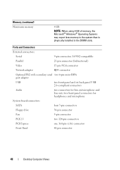
... PCI Express one 164-pin (x16) connector Front Panel 40-pin connector 40 Desktop Computer Views Memory (continued) Maximum memory 4 GB NOTE: When using 4 GB of memory, the Microsoft® Windows® Operating Systems may report less memory in the system than is physically installed in /microphone and line-out; two front-panel connectors...
... PCI Express one 164-pin (x16) connector Front Panel 40-pin connector 40 Desktop Computer Views Memory (continued) Maximum memory 4 GB NOTE: When using 4 GB of memory, the Microsoft® Windows® Operating Systems may report less memory in the system than is physically installed in /microphone and line-out; two front-panel connectors...
User's Guide
Page 66
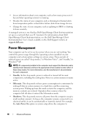
...; XP. • Access information about Dell OpenManage Client Instrumentation, see the manufacturer's documentation for each component. • Standby. For information about your computer, such as listening for thermal alerts from temperature probes or hard-drive failure alerts from this mode restarts the computer, and the memory contents are called "sleep modes," in...
...; XP. • Access information about Dell OpenManage Client Instrumentation, see the manufacturer's documentation for each component. • Standby. For information about your computer, such as listening for thermal alerts from temperature probes or hard-drive failure alerts from this mode restarts the computer, and the memory contents are called "sleep modes," in...


