
Quick Reference
Page 37
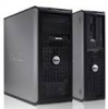
...) 6 front-panel connector (FRONTPANEL) 8 SATA drive connectors (SATA2, SATA3) 10 password jumper (PSWD) 12 PCI Express x16 card connector (SLOT1) 14 internal buzzer (SPKR) 16 fan connector (FAN_CPU) Replacing the Computer Cover CAUTION: Before you begin any of the procedures in this section, follow the safety instructions located in the Product...
...) 6 front-panel connector (FRONTPANEL) 8 SATA drive connectors (SATA2, SATA3) 10 password jumper (PSWD) 12 PCI Express x16 card connector (SLOT1) 14 internal buzzer (SPKR) 16 fan connector (FAN_CPU) Replacing the Computer Cover CAUTION: Before you begin any of the procedures in this section, follow the safety instructions located in the Product...
Quick Reference
Page 47
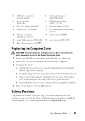
...PSWD) 12 PCI Express x16 card connector (SLOT1) 14 internal buzzer (SPKR) 16 fan connector (FAN_CPU) Replacing the Computer Cover CAUTION: Before you if your computer, see the Dell support website at support.dell.com. Quick Reference Guide 47 b Using the hinge tabs as expected. d Ensure ...latest troubleshooting information available for your computer does not perform as leverage, rotate the cover downward to the upright position. Solving Problems Dell provides a number of the computer. c Snap the cover into place by pulling back on the cover release latch and then releasing...
...PSWD) 12 PCI Express x16 card connector (SLOT1) 14 internal buzzer (SPKR) 16 fan connector (FAN_CPU) Replacing the Computer Cover CAUTION: Before you if your computer, see the Dell support website at support.dell.com. Quick Reference Guide 47 b Using the hinge tabs as expected. d Ensure ...latest troubleshooting information available for your computer does not perform as leverage, rotate the cover downward to the upright position. Solving Problems Dell provides a number of the computer. c Snap the cover into place by pulling back on the cover release latch and then releasing...
Quick Reference
Page 55
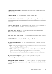
CPU fan failure. The floppy disk may be defective or a cable may not match the hardware configuration. H A R D - A chip on the system board might be ...floppy disk from drive A and restart the computer. K E Y B O A R D F A I L U R E - Check cables /swap hard disks. Keyboard failure or keyboard cable loose. C P U F A N F A I L U R E - D I S K D R I V E R E A D F A I L U R E - N O B O O T D E V I C E A V A I L A B L E - Replace the CPU fan. Replace the floppy disk with one that the boot sequence information is correct. C M O S C H E C K S U M E R R O R -
CPU fan failure. The floppy disk may be defective or a cable may not match the hardware configuration. H A R D - A chip on the system board might be ...floppy disk from drive A and restart the computer. K E Y B O A R D F A I L U R E - Check cables /swap hard disks. Keyboard failure or keyboard cable loose. C P U F A N F A I L U R E - D I S K D R I V E R E A D F A I L U R E - N O B O O T D E V I C E A V A I L A B L E - Replace the CPU fan. Replace the floppy disk with one that the boot sequence information is correct. C M O S C H E C K S U M E R R O R -
User's Guide
Page 28
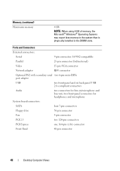
... Ports and Connectors External connectors: Serial Parallel Video Network adapter Optional PS/2 with secondary serial port adapter USB Audio System board connectors: SATA Floppy drive Fan PCI 2.3 PCI Express Front Panel 4 GB NOTE: When using 4 GB of memory, the Microsoft® Windows® Operating Systems may report less memory in the...
... Ports and Connectors External connectors: Serial Parallel Video Network adapter Optional PS/2 with secondary serial port adapter USB Audio System board connectors: SATA Floppy drive Fan PCI 2.3 PCI Express Front Panel 4 GB NOTE: When using 4 GB of memory, the Microsoft® Windows® Operating Systems may report less memory in the...
User's Guide
Page 40
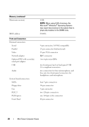
... six back panel USB 2.0-compliant connectors Audio two connectors for headphones and microphone System board connectors: SATA four 7-pin connectors Floppy drive 34-pin connector Fan 5-pin connector PCI 2.3 two 120-pin connectors PCI Express one 164-pin (x16) connector Front Panel 40-pin connector 40 Desktop Computer Views
... six back panel USB 2.0-compliant connectors Audio two connectors for headphones and microphone System board connectors: SATA four 7-pin connectors Floppy drive 34-pin connector Fan 5-pin connector PCI 2.3 two 120-pin connectors PCI Express one 164-pin (x16) connector Front Panel 40-pin connector 40 Desktop Computer Views
User's Guide
Page 66
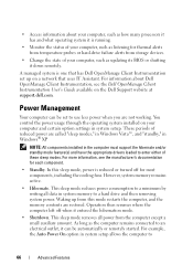
... hard drive and then removing system power. Operation then resumes where the computer left off for most components, including the cooling fans. For information about your computer, such as listening for thermal alerts from temperature probes or hard-drive failure alerts from this ...sleep mode, power is reduced or turned off when it down remotely. • Access information about Dell OpenManage Client Instrumentation, see the manufacturer's documentation for each component. • Standby. Power Management Your computer can be set up from...
... hard drive and then removing system power. Operation then resumes where the computer left off for most components, including the cooling fans. For information about your computer, such as listening for thermal alerts from temperature probes or hard-drive failure alerts from this ...sleep mode, power is reduced or turned off when it down remotely. • Access information about Dell OpenManage Client Instrumentation, see the manufacturer's documentation for each component. • Standby. Power Management Your computer can be set up from...

User's Guide
Page 104
... the same error (see "Removing the Processor and Heat Sink" on page 197). Replace the CPU fan (see "Contacting Dell" on page 267 for assistance). A cable may be loose, or the computer configuration information may be...P O I N T A N D C O N T A C T D E L L TE C H N I L U R E - ALERT! C M O S C H E C K S U M E R R O R - Replace battery (see "Replacing the Battery" on page 190 or see "Contacting Dell" on page 267 for a loose cable connection. CPU fan failure. Possible motherboard failure or RTC battery low. The floppy disk may be loose. Possible hard disk drive failure during HDD...
... the same error (see "Removing the Processor and Heat Sink" on page 197). Replace the CPU fan (see "Contacting Dell" on page 267 for assistance). A cable may be loose, or the computer configuration information may be...P O I N T A N D C O N T A C T D E L L TE C H N I L U R E - ALERT! C M O S C H E C K S U M E R R O R - Replace battery (see "Replacing the Battery" on page 190 or see "Contacting Dell" on page 267 for a loose cable connection. CPU fan failure. Possible motherboard failure or RTC battery low. The floppy disk may be loose. Possible hard disk drive failure during HDD...

User's Guide
Page 127
... volume setting. R E I N S T A L L T H E S C A N N E R D R I N T E R F E R E N C E - See the setup diagram supplied with another device, such as shown on the media player(s) has not been turned down or off nearby fans, fluorescent lights, or Troubleshooting 127 E L I M I N A T E P O S S I B L E I V E R - • Ensure that the speakers are connected to the card. See the scanner documentation for instructions. Sound and Speaker Problems...
... volume setting. R E I N S T A L L T H E S C A N N E R D R I N T E R F E R E N C E - See the setup diagram supplied with another device, such as shown on the media player(s) has not been turned down or off nearby fans, fluorescent lights, or Troubleshooting 127 E L I M I N A T E P O S S I B L E I V E R - • Ensure that the speakers are connected to the card. See the scanner documentation for instructions. Sound and Speaker Problems...

User's Guide
Page 129
... area you want to appear shaky. See "Diagnostic Lights" on adjusting the contrast and brightness, demagnetizing (degaussing) the monitor, and running the monitor self-test. Fans, fluorescent lights, halogen lamps, and other electrical devices can cause the screen image to change or click the Display icon. 3 Try different settings for Color...
... area you want to appear shaky. See "Diagnostic Lights" on adjusting the contrast and brightness, demagnetizing (degaussing) the monitor, and running the monitor self-test. Fans, fluorescent lights, halogen lamps, and other electrical devices can cause the screen image to change or click the Display icon. 3 Try different settings for Color...
User's Guide
Page 144
..., laceration by your warranty. The computer turns off after the operating system shutdown process is complete. 2 Ensure that is not authorized by Dell is not covered by moving fan blades, or other unexpected injuries, always unplug your computer from potential damage and to help protect your operating system, press and hold the...
..., laceration by your warranty. The computer turns off after the operating system shutdown process is complete. 2 Ensure that is not authorized by Dell is not covered by moving fan blades, or other unexpected injuries, always unplug your computer from potential damage and to help protect your operating system, press and hold the...

User's Guide
Page 147
... or the surface on its side with the computer cover facing up. CAUTION: Some of the procedures in this chapter may be replacable by moving fan blades, or other unexpected injuries, always unplug your computer on which it is resting. 2 Lay your computer from the electrical outlet before removing the cover...
... or the surface on its side with the computer cover facing up. CAUTION: Some of the procedures in this chapter may be replacable by moving fan blades, or other unexpected injuries, always unplug your computer on which it is resting. 2 Lay your computer from the electrical outlet before removing the cover...
User's Guide
Page 158
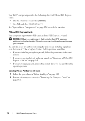
... your computer and you are installing a graphics card that run higher than 75 W require an additional cooling fan installed. NOTICE: PCI Express graphics cards that runs at 75 W or higher, Contact Dell to purchase a card fan. • If you are installing or replacing a card, follow the procedures in "Before You Begin" on page...
... your computer and you are installing a graphics card that run higher than 75 W require an additional cooling fan installed. NOTICE: PCI Express graphics cards that runs at 75 W or higher, Contact Dell to purchase a card fan. • If you are installing or replacing a card, follow the procedures in "Before You Begin" on page...

User's Guide
Page 164
... bar. • The notch in the top of the card or filler bracket fits around the alignment guide. 8 Fix the card retention bracket by moving fan blades, or other unexpected injuries, always unplug your computer from the operating system. 12 If you removed a sound card: a Enter system setup (see "Back Panel...
... bar. • The notch in the top of the card or filler bracket fits around the alignment guide. 8 Fix the card retention bracket by moving fan blades, or other unexpected injuries, always unplug your computer from the operating system. 12 If you removed a sound card: a Enter system setup (see "Back Panel...

User's Guide
Page 168
Hard Drives CAUTION: Before you are keyed for correct insertion; CAUTION: To guard against electrical shock, laceration by moving fan blades, or other connector. Check the documentation for your computer. NOTICE: To avoid damage to keep, back up your computer from the electrical outlet before ...
Hard Drives CAUTION: Before you are keyed for correct insertion; CAUTION: To guard against electrical shock, laceration by moving fan blades, or other connector. Check the documentation for your computer. NOTICE: To avoid damage to keep, back up your computer from the electrical outlet before ...
User's Guide
Page 174
... shock, laceration by squeezing the release tabs and gently pulling the bracket up your computer from the inside of the hard-drive bay by moving fan blades, or other unexpected injuries, always unplug your files before removing the cover. NOTICE: If you are replacing a hard drive that contains data you want...
... shock, laceration by squeezing the release tabs and gently pulling the bracket up your computer from the inside of the hard-drive bay by moving fan blades, or other unexpected injuries, always unplug your files before removing the cover. NOTICE: If you are replacing a hard drive that contains data you want...

User's Guide
Page 180
CAUTION: To guard against electrical shock, laceration by moving fan blades, or other unexpected injuries, always unplug your computer from the system board. 6 Slide the drive release latch downward and hold it in the Product ...
CAUTION: To guard against electrical shock, laceration by moving fan blades, or other unexpected injuries, always unplug your computer from the system board. 6 Slide the drive release latch downward and hold it in the Product ...

User's Guide
Page 184
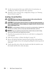
1 2 3 1 power cable 3 floppy-drive connector (FLOPPY) 2 floppy-drive cable 9 Replace the bezel (see "Replacing the Computer Cover" on . 184 Mini Tower Computer Parts NOTICE: To connect a network cable, first plug the cable into the network device and then plug it into the computer. 12 Connect your computer and devices to avoid blocking airflow between the fan and cooling vents. 11 Replace the computer cover (see "Replacing the Bezel" on page 166). 10 Check all cable connections, and fold cables out of the way to their electrical outlets, and turn them on page 207).
1 2 3 1 power cable 3 floppy-drive connector (FLOPPY) 2 floppy-drive cable 9 Replace the bezel (see "Replacing the Computer Cover" on . 184 Mini Tower Computer Parts NOTICE: To connect a network cable, first plug the cable into the network device and then plug it into the computer. 12 Connect your computer and devices to avoid blocking airflow between the fan and cooling vents. 11 Replace the computer cover (see "Replacing the Bezel" on page 166). 10 Check all cable connections, and fold cables out of the way to their electrical outlets, and turn them on page 207).

User's Guide
Page 185
...follow the safety instructions located in place. CAUTION: To guard against electrical shock, laceration by moving fan blades, or other unexpected injuries, always unplug your computer works correctly by running the Dell Diagnostics (see "Removing the Bezel" on page 111). Removing an Optical Drive 1 Follow the... page 143. 2 Remove the computer cover (see "Removing the Computer Cover" on page 147). 3 Remove the bezel (see "Dell Diagnostics" on page 165). 4 Disconnect the optical drive data cable from the electrical outlet before removing the cover. Mini Tower Computer Parts 185
...follow the safety instructions located in place. CAUTION: To guard against electrical shock, laceration by moving fan blades, or other unexpected injuries, always unplug your computer works correctly by running the Dell Diagnostics (see "Removing the Bezel" on page 111). Removing an Optical Drive 1 Follow the... page 143. 2 Remove the computer cover (see "Removing the Computer Cover" on page 147). 3 Remove the bezel (see "Dell Diagnostics" on page 165). 4 Disconnect the optical drive data cable from the electrical outlet before removing the cover. Mini Tower Computer Parts 185

User's Guide
Page 189
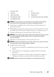
Mini Tower Computer Parts 189 1 2 3 1 power cable 3 optical drive connector 2 optical drive data cable 8 Check all cable connections, and fold cables out of the way to avoid blocking airflow between the fan and cooling vents. 9 Replace the drive panel by aligning its hinges and rotating it up until it into place. 10 Replace the bezel (see "Replacing the Bezel" on page 166). 11 Replace the computer cover (see "Replacing the Computer Cover" on page 207). NOTICE: To connect a network cable, first plug the cable into the network device and then plug it snaps into the computer.
Mini Tower Computer Parts 189 1 2 3 1 power cable 3 optical drive connector 2 optical drive data cable 8 Check all cable connections, and fold cables out of the way to avoid blocking airflow between the fan and cooling vents. 9 Replace the drive panel by aligning its hinges and rotating it up until it into place. 10 Replace the bezel (see "Replacing the Bezel" on page 166). 11 Replace the computer cover (see "Replacing the Computer Cover" on page 207). NOTICE: To connect a network cable, first plug the cable into the network device and then plug it snaps into the computer.
User's Guide
Page 201
.... NOTICE: Ensure that the heat sink assembly is installed. 9 Install the heat sink assembly: a Place the heat sink and fan assembly back onto the heat-sink assembly bracket. b Ensure that the processor is a requirement for ensuring adequate thermal bonding, which is positioned correctly. 6 While ...NOTICE: Ensure that they are aligned with the socket, and do not use excessive force when you apply new thermal grease. c Hold the heat sink fan assembly in the socket and ensure that the two clamp grips are pinched when the heat sink assembly is correctly seated and secure.
.... NOTICE: Ensure that the heat sink assembly is installed. 9 Install the heat sink assembly: a Place the heat sink and fan assembly back onto the heat-sink assembly bracket. b Ensure that the processor is a requirement for ensuring adequate thermal bonding, which is positioned correctly. 6 While ...NOTICE: Ensure that they are aligned with the socket, and do not use excessive force when you apply new thermal grease. c Hold the heat sink fan assembly in the socket and ensure that the two clamp grips are pinched when the heat sink assembly is correctly seated and secure.


