
User's Guide
Page 8
... Inside View of Your Computer 149 System Board Components 150 Power Supply DC Connector Pin Assignments . . . . . 152 Memory 155 Installation Guidelines 155 Installing Memory 156 Removing Memory 157 Cards 157 PCI and PCI Express Cards 158 Bezel 164 Removing the Bezel 165 Replacing the Bezel 166 Drives 166 Recommended Drive Cable Connections . . . . . 167...
... Inside View of Your Computer 149 System Board Components 150 Power Supply DC Connector Pin Assignments . . . . . 152 Memory 155 Installation Guidelines 155 Installing Memory 156 Removing Memory 157 Cards 157 PCI and PCI Express Cards 158 Bezel 164 Removing the Bezel 165 Replacing the Bezel 166 Drives 166 Recommended Drive Cable Connections . . . . . 167...
User's Guide
Page 9
Battery 190 Replacing the Battery 190 Power Supply 192 Replacing the Power Supply 192 Speakers 194 Installing a Speaker 194 Removing a Speaker 195 Processor 196 Removing the Processor and Heat Sink 197 Installing the Processor and Heat Sink... System Board 205 Removing the System Board 205 Installing the System Board 207 Replacing the Computer Cover 207 13 Desktop Computer Parts 209 Removing the Computer Cover 209 Inside View of Your Computer 210 System Board Components 212 Power Supply DC Connector Pin Assignments . . . . . 214 Memory 217 Installation Guidelines 217 ...
Battery 190 Replacing the Battery 190 Power Supply 192 Replacing the Power Supply 192 Speakers 194 Installing a Speaker 194 Removing a Speaker 195 Processor 196 Removing the Processor and Heat Sink 197 Installing the Processor and Heat Sink... System Board 205 Removing the System Board 205 Installing the System Board 207 Replacing the Computer Cover 207 13 Desktop Computer Parts 209 Removing the Computer Cover 209 Inside View of Your Computer 210 System Board Components 212 Power Supply DC Connector Pin Assignments . . . . . 214 Memory 217 Installation Guidelines 217 ...

User's Guide
Page 10
... 227 Drive Interface Connectors 228 Connecting and Disconnecting Drive Cables . . . 228 Hard Drives 229 Floppy Drive 233 Optical Drive 237 Battery 241 Replacing the Battery 241 Power Supply 242 Replacing the Power Supply 243 Speakers 245 Installing a Speaker 245 Removing a Speaker 246 Processor 247 Removing the Processor and Heat Sink 247 Installing the Processor 249 I/O Panel...
... 227 Drive Interface Connectors 228 Connecting and Disconnecting Drive Cables . . . 228 Hard Drives 229 Floppy Drive 233 Optical Drive 237 Battery 241 Replacing the Battery 241 Power Supply 242 Replacing the Power Supply 243 Speakers 245 Installing a Speaker 245 Removing a Speaker 246 Processor 247 Removing the Processor and Heat Sink 247 Installing the Processor 249 I/O Panel...
User's Guide
Page 192
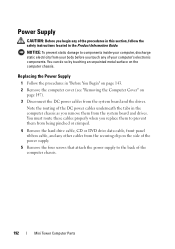
...and the drives. You can do so by touching an unpainted metal surface on page 147). 3 Disconnect the DC power cables from the system board and drives. Replacing the Power Supply 1 Follow the procedures in the computer chassis as you remove them to the back of the computer chassis. 192 Mini... Tower Computer Parts Power Supply CAUTION: Before you begin any of your body before you touch any of the procedures in ...
...and the drives. You can do so by touching an unpainted metal surface on page 147). 3 Disconnect the DC power cables from the system board and drives. Replacing the Power Supply 1 Follow the procedures in the computer chassis as you remove them to the back of the computer chassis. 192 Mini... Tower Computer Parts Power Supply CAUTION: Before you begin any of your body before you touch any of the procedures in ...

User's Guide
Page 193
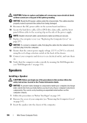
Mini Tower Computer Parts 193 1 2 3 4 5 1 release button 3 screws (4) 5 AC power connector 2 power supply 4 voltage selection switch (red) 6 Slide the power supply towards the front of the computer and lift it out. 7 Place and slide the replacement power supply toward the back of the computer. 8 Replace and tighten all screws that secure the power supply to the back of the computer chassis.
Mini Tower Computer Parts 193 1 2 3 4 5 1 release button 3 screws (4) 5 AC power connector 2 power supply 4 voltage selection switch (red) 6 Slide the power supply towards the front of the computer and lift it out. 7 Place and slide the replacement power supply toward the back of the computer. 8 Replace and tighten all screws that secure the power supply to the back of the computer chassis.
User's Guide
Page 194
...CD or DVD drive data cable, and the front panel ribbon cable to the securing clip on the side of the power supply. You can do so by running the Dell Diagnostics (see "Dell Diagnostics" on page 147). 3 Insert the speaker into the chassis of the computer. 194 Mini Tower Computer Parts NOTICE...cables must be properly routed to prevent the cables from your body before you begin any of your computer (see "Replacing the Computer Cover" on page 207). CAUTION: Failure to replace and tighten all cable connections to make sure they are a key part of the system grounding. NOTICE: Route the...
...CD or DVD drive data cable, and the front panel ribbon cable to the securing clip on the side of the power supply. You can do so by running the Dell Diagnostics (see "Dell Diagnostics" on page 147). 3 Insert the speaker into the chassis of the computer. 194 Mini Tower Computer Parts NOTICE...cables must be properly routed to prevent the cables from your body before you begin any of your computer (see "Replacing the Computer Cover" on page 207). CAUTION: Failure to replace and tighten all cable connections to make sure they are a key part of the system grounding. NOTICE: Route the...
User's Guide
Page 205
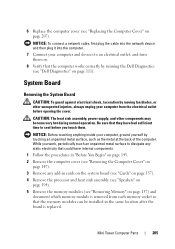
...cool before opening the cover. CAUTION: The heat sink assembly, power supply, and other unexpected injuries, always unplug your computer from each memory socket so that the computer works correctly by running the Dell Diagnostics (see "Dell Diagnostics" on page 111). System Board Removing the System Board... Parts 205 NOTICE: Before touching anything inside your computer and devices to an electrical outlet, and turn them . 6 Replace the computer cover (see "Replacing the Computer Cover" on page 147). 3 Remove any add-in the same location after the board is removed from the...
...cool before opening the cover. CAUTION: The heat sink assembly, power supply, and other unexpected injuries, always unplug your computer from each memory socket so that the computer works correctly by running the Dell Diagnostics (see "Dell Diagnostics" on page 111). System Board Removing the System Board... Parts 205 NOTICE: Before touching anything inside your computer and devices to an electrical outlet, and turn them . 6 Replace the computer cover (see "Replacing the Computer Cover" on page 147). 3 Remove any add-in the same location after the board is removed from the...
User's Guide
Page 242
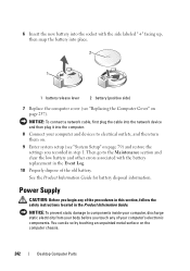
... with the side labeled "+" facing up, then snap the battery into place. 2 1 1 battery release lever 2 battery (positive side) 7 Replace the computer cover (see "System Setup" on the computer chassis. 242 Desktop Computer Parts You can do so by touching an unpainted metal surface... static electricity from your body before you touch any of the procedures in this section, follow the safety instructions located in step 1. Power Supply CAUTION: Before you recorded in the Product Information Guide. See the Product Information Guide for battery disposal information. NOTICE: To connect a...
... with the side labeled "+" facing up, then snap the battery into place. 2 1 1 battery release lever 2 battery (positive side) 7 Replace the computer cover (see "System Setup" on the computer chassis. 242 Desktop Computer Parts You can do so by touching an unpainted metal surface... static electricity from your body before you touch any of the procedures in this section, follow the safety instructions located in step 1. Power Supply CAUTION: Before you recorded in the Product Information Guide. See the Product Information Guide for battery disposal information. NOTICE: To connect a...
User's Guide
Page 243
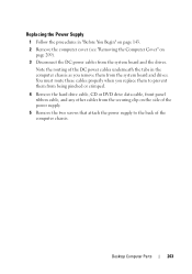
... cover (see "Removing the Computer Cover" on the side of the computer chassis. Replacing the Power Supply 1 Follow the procedures in the computer chassis as you replace them to the back of the power supply. 5 Remove the two screws that attach the power supply to prevent them from being pinched or crimped. 4 Remove the hard drive cable, CD...
... cover (see "Removing the Computer Cover" on the side of the computer chassis. Replacing the Power Supply 1 Follow the procedures in the computer chassis as you replace them to the back of the power supply. 5 Remove the two screws that attach the power supply to prevent them from being pinched or crimped. 4 Remove the hard drive cable, CD...
User's Guide
Page 244
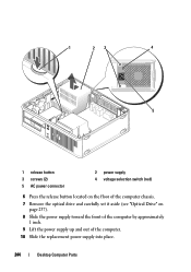
1 23 4 5 1 release button 3 screws (2) 5 AC power connector 2 power supply 4 voltage selection switch (red) 6 Press the release button located on the floor of the computer chassis. 7 Remove the optical drive and carefully set it aside (see "Optical Drive" on page 237). 8 Slide the power supply toward the front of the computer by approximately 1 inch. 9 Lift the power supply up and out of the computer. 10 Slide the replacement power supply into place. 244 Desktop Computer Parts
1 23 4 5 1 release button 3 screws (2) 5 AC power connector 2 power supply 4 voltage selection switch (red) 6 Press the release button located on the floor of the computer chassis. 7 Remove the optical drive and carefully set it aside (see "Optical Drive" on page 237). 8 Slide the power supply toward the front of the computer by approximately 1 inch. 9 Lift the power supply up and out of the computer. 10 Slide the replacement power supply into place. 244 Desktop Computer Parts

User's Guide
Page 245
... Verify that secure the power supply to the securing clip on page 143. 2 Remove the cover of the power supply. Desktop Computer Parts 245 NOTE: Double-check all screws may cause electrical shock as these screws are secure. 14 Replace the computer cover (see "Replacing the Computer Cover" on... your computer's electronic components. You can do so by running the Dell Diagnostics (see "Removing the Computer Cover" on page 209). NOTICE: Route the DC power cables under the chassis tabs. 11 Replace the screws that the computer works correctly by touching an unpainted metal ...
... Verify that secure the power supply to the securing clip on page 143. 2 Remove the cover of the power supply. Desktop Computer Parts 245 NOTE: Double-check all screws may cause electrical shock as these screws are secure. 14 Replace the computer cover (see "Replacing the Computer Cover" on... your computer's electronic components. You can do so by running the Dell Diagnostics (see "Removing the Computer Cover" on page 209). NOTICE: Route the DC power cables under the chassis tabs. 11 Replace the screws that the computer works correctly by touching an unpainted metal ...
User's Guide
Page 255
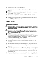
CAUTION: The heat sink assembly, power supply, and other unexpected injuries, always unplug your computer, ground yourself by running the Dell Diagnostics (see "Removing the Computer Cover" on . 8 Verify that the computer works correctly by touching an unpainted metal surface, such as... plug the cable into the network device and then plug it into the computer. 7 Connect your computer and devices to the system board. 6 Replace the computer cover (see "Removing Memory" on page 257). NOTICE: Before touching anything inside your computer from the system board. 5 Reconnect the ...
CAUTION: The heat sink assembly, power supply, and other unexpected injuries, always unplug your computer, ground yourself by running the Dell Diagnostics (see "Removing the Computer Cover" on . 8 Verify that the computer works correctly by touching an unpainted metal surface, such as... plug the cable into the network device and then plug it into the computer. 7 Connect your computer and devices to the system board. 6 Replace the computer cover (see "Removing Memory" on page 257). NOTICE: Before touching anything inside your computer from the system board. 5 Reconnect the ...


