Service Manual
Page 4
... 4-4 ZIF Connectors 4-5 Field-Replaceable Parts and Assemblies 4-6 Hard-Disk Drive Assembly 4-7 Memory Compartment Cover 4-8 Memory Modules 4-9 Palmrest Assembly 4-10 Trackball Assembly 4-13 Keyboard Assembly 4-14 Display Assembly 4-16 Tilt-Support Foot 4-16 Display Assembly 4-18 Display Assembly Bezel 4-20 Display Assembly Latch and Latch Spring 4-21 LCD Panel 4-22 LCD Inverter Board 4-24 Hinge Covers 4-25 Display-Assembly Interface Cable 4-26 Microphone/Switch Assembly 4-28 Bottom Case Assembly 4-29 Diskette/CD-ROM Drive Assembly 4-31 Deck Buoy...
... 4-4 ZIF Connectors 4-5 Field-Replaceable Parts and Assemblies 4-6 Hard-Disk Drive Assembly 4-7 Memory Compartment Cover 4-8 Memory Modules 4-9 Palmrest Assembly 4-10 Trackball Assembly 4-13 Keyboard Assembly 4-14 Display Assembly 4-16 Tilt-Support Foot 4-16 Display Assembly 4-18 Display Assembly Bezel 4-20 Display Assembly Latch and Latch Spring 4-21 LCD Panel 4-22 LCD Inverter Board 4-24 Hinge Covers 4-25 Display-Assembly Interface Cable 4-26 Microphone/Switch Assembly 4-28 Bottom Case Assembly 4-29 Diskette/CD-ROM Drive Assembly 4-31 Deck Buoy...

Service Manual
Page 12
... charged. 1-4 Dell Latitude XPi CD Service Manual The indicator turns on the outside of the indicators. The subsections that the computer is an amber LED. After the computer is turned on the keyboard assembly. Low-Battery Indicator The low-battery indicator is receiving stable power. The portable computer has nine indicators: six on the display assembly's indicator panel and three on , the power/suspend indicator lights up constantly to or from the hard-disk drive or the CD-ROM. The indicator lights...
... charged. 1-4 Dell Latitude XPi CD Service Manual The indicator turns on the outside of the indicators. The subsections that the computer is an amber LED. After the computer is turned on the keyboard assembly. Low-Battery Indicator The low-battery indicator is receiving stable power. The portable computer has nine indicators: six on the display assembly's indicator panel and three on , the power/suspend indicator lights up constantly to or from the hard-disk drive or the CD-ROM. The indicator lights...

Service Manual
Page 24
... detected or the computer is in suspend mode. If the computer is operating from AC power and move it reaches full capacity. 2-2 Dell Latitude XPi CD Service Manual Verify that the user has saved all open files and exited all open the display and slide the power button to turn off the computer. • Low-battery indicator is on or blinking - CAUTION: Before you proceed with the visual inspection...
... detected or the computer is in suspend mode. If the computer is operating from AC power and move it reaches full capacity. 2-2 Dell Latitude XPi CD Service Manual Verify that the user has saved all open files and exited all open the display and slide the power button to turn off the computer. • Low-battery indicator is on or blinking - CAUTION: Before you proceed with the visual inspection...

Service Manual
Page 25
... the memory modules. 9. mentation for the monitor. • The monitor and its associated switches operate freely. 12. Remove any installed PC Cards from battery power, remove the main battery assembly, verify that the trackball and its interface cable are set according to the appro- 5. Verify that they are free of any obvious physical damage. • The mouse's ball and push buttons operate freely. 14. Turn off the computer. priate port connector...
... the memory modules. 9. mentation for the monitor. • The monitor and its associated switches operate freely. 12. Remove any installed PC Cards from battery power, remove the main battery assembly, verify that the trackball and its interface cable are set according to the appro- 5. Verify that they are free of any obvious physical damage. • The mouse's ball and push buttons operate freely. 14. Turn off the computer. priate port connector...

Service Manual
Page 26
... for any indications of problems. NOTE: To prevent possible damage to Table 3-2. 2-4 Dell Latitude XPi CD Service Manual Watch the indicators on all three indica- Proceed to step 4. Turn off the computer and any attached peripherals and then the computer. Dell recommends that indicates an error condition. Turn on the top of the diagnostics diskette when servicing a user's computer. To observe the boot routine, follow these indicators light up...
... for any indications of problems. NOTE: To prevent possible damage to Table 3-2. 2-4 Dell Latitude XPi CD Service Manual Watch the indicators on all three indica- Proceed to step 4. Turn off the computer and any attached peripherals and then the computer. Dell recommends that indicates an error condition. Turn on the top of the diagnostics diskette when servicing a user's computer. To observe the boot routine, follow these indicators light up...
Service Manual
Page 31
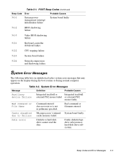
... external PS/2 mouse failed. Cache disabled due to failure Microprocessor's internal System board faulty. cache memory failed. Table 3-1. Table 3-2. Faulty diskette/tape drive subsystem or hard-disk drive subsystem. or external PS/2 mouse faulty. Bad command or File Name Command entered does not exist or is not in alphabetical order) system error messages that may appear on the display during the boot routine or during normal computer operation...
... external PS/2 mouse failed. Cache disabled due to failure Microprocessor's internal System board faulty. cache memory failed. Table 3-1. Table 3-2. Faulty diskette/tape drive subsystem or hard-disk drive subsystem. or external PS/2 mouse faulty. Bad command or File Name Command entered does not exist or is not in alphabetical order) system error messages that may appear on the display during the boot routine or during normal computer operation...
Service Manual
Page 33
... computer. System board faulty. Computer needs rebooting. Gate A20 failure Computer cannot enable protective mode. Keyboard not responding. Installed hard-disk drive not compatible with computer. Table 3-2. Computer cannot identify hard-disk drive type. System Error Messages (Continued) Message Definition Probable Causes Extended memory Amount of memory size has changed recorded in NVRAM not matching memory installed in System Setup. Reserve battery weak or depleted. System Setup contains invalid settings. Hard-disk drive or controller not responding to...
... computer. System board faulty. Computer needs rebooting. Gate A20 failure Computer cannot enable protective mode. Keyboard not responding. Installed hard-disk drive not compatible with computer. Table 3-2. Computer cannot identify hard-disk drive type. System Error Messages (Continued) Message Definition Probable Causes Extended memory Amount of memory size has changed recorded in NVRAM not matching memory installed in System Setup. Reserve battery weak or depleted. System Setup contains invalid settings. Hard-disk drive or controller not responding to...

Service Manual
Page 34
... Memory allocation error Memory control logic not operating properly. Installed memory module faulty or improperly seated. System Error Messages (Continued) Message Definition Probable Causes Keyboard stuck key failure Keyboard key(s) jammed. For external keyboard or keypad, cable or connector loose or keyboard faulty. For built-in use conflicts with the operating system, an application program, or a utility For either keyboard, key may have been pressed while computer was booting. Table 3-2. Faulty application program 3-6 Dell Latitude XPi CD Service Manual...
... Memory allocation error Memory control logic not operating properly. Installed memory module faulty or improperly seated. System Error Messages (Continued) Message Definition Probable Causes Keyboard stuck key failure Keyboard key(s) jammed. For external keyboard or keypad, cable or connector loose or keyboard faulty. For built-in use conflicts with the operating system, an application program, or a utility For either keyboard, key may have been pressed while computer was booting. Table 3-2. Faulty application program 3-6 Dell Latitude XPi CD Service Manual...

Service Manual
Page 36
... mode Keyboard/mouse controller malfunctioning, or memory module(s) not responding. Tests the keyboard subsystem • Mouse - Tests the CD-ROM drive subsystem 3-8 Dell Latitude XPi CD Service Manual reset. Timer chip Timer circuit on diskette or hard-disk drive. Tests the diskette drive subsystem • Hard-Disk Drives (Non-SCSI) - Time-of -day not set-please run the System Setup program. Time-of-day clock stopped Time-of -day System clock stopped. Main battery has lost its charge. System board...
... mode Keyboard/mouse controller malfunctioning, or memory module(s) not responding. Tests the keyboard subsystem • Mouse - Tests the CD-ROM drive subsystem 3-8 Dell Latitude XPi CD Service Manual reset. Timer chip Timer circuit on diskette or hard-disk drive. Tests the diskette drive subsystem • Hard-Disk Drives (Non-SCSI) - Time-of -day not set-please run the System Setup program. Time-of-day clock stopped Time-of -day System clock stopped. Main battery has lost its charge. System board...
Service Manual
Page 37
... the serial communication port • Parallel Ports - If a main memory error is loading. To start the diagnostics, turn off the computer, insert a diagnostics diskette into the diskette drive, and then turn on the screen telling you which memory address failed. • Serial Ports - Runs all test groups to quickly locate the failure or to indicate where further testing may be needed to the original diagnostics diskette, always use a backup...
... the serial communication port • Parallel Ports - If a main memory error is loading. To start the diagnostics, turn off the computer, insert a diagnostics diskette into the diskette drive, and then turn on the screen telling you which memory address failed. • Serial Ports - Runs all test groups to quickly locate the failure or to indicate where further testing may be needed to the original diagnostics diskette, always use a backup...

Service Manual
Page 83
...; Nut drivers Precautionary Measures Before you begin working on the computer, read about the precautionary measures, screw identification, and computer orientation outlined at the beginning of the procedures in the field. Factory Repair Parts A-1 The subsections that follow Table A-1 provide instructions for the computer. For removal and replacement procedures for removing and replacing factory com- Factory Repair Parts and Assemblies Table A-1 lists the factory repair parts and assemblies...
...; Nut drivers Precautionary Measures Before you begin working on the computer, read about the precautionary measures, screw identification, and computer orientation outlined at the beginning of the procedures in the field. Factory Repair Parts A-1 The subsections that follow Table A-1 provide instructions for the computer. For removal and replacement procedures for removing and replacing factory com- Factory Repair Parts and Assemblies Table A-1 lists the factory repair parts and assemblies...
Service Manual
Page 113
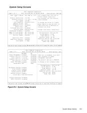
... CPU Mode: Enabled Brightness: Low AC Disabled Disabled Disabled Disabled Disabled Disabled High When set to decrease or increase the value. System Setup Screens System Setup Options B-3 Changes take effect immediately. A change values Alt-P next Esc exit Alt-B reboot Page 2 of 2 Dell Computer Corporation Dell Latitude XPi CD System Setup BIOS Version: AXX XXX Time: 13:17:02Date: Mon Feb 12, 1997 Internal Hard Drive: Diskette Drive A: Boot Speed: Boot Sequence: Speaker Volume: Keyboard Click: Serial Port: Infrared Data Port: Parallel Mode: Integrated Trackball: Upper PC Card...
... CPU Mode: Enabled Brightness: Low AC Disabled Disabled Disabled Disabled Disabled Disabled High When set to decrease or increase the value. System Setup Screens System Setup Options B-3 Changes take effect immediately. A change values Alt-P next Esc exit Alt-B reboot Page 2 of 2 Dell Computer Corporation Dell Latitude XPi CD System Setup BIOS Version: AXX XXX Time: 13:17:02Date: Mon Feb 12, 1997 Internal Hard Drive: Diskette Drive A: Boot Speed: Boot Sequence: Speaker Volume: Keyboard Click: Serial Port: Infrared Data Port: Parallel Mode: Integrated Trackball: Upper PC Card...

Service Manual
Page 114
... key combination that directs where computer's video image is sent (the built-in parallel port is installed but not being used. BOOT SPEED Indicates operating frequency at which computer boots-processor's rated speed or a slower speed for power conservation or speedsensitive software. Table B-1. DATE Resets date on computer's internal clock. B-4 Dell Latitude XPi CD Service Manual INTERNAL HARD DRIVE Displays capacity of diskette drive installed. INTEGRATED TRACKBALL Enables computer's integrated trackball. Set to DISABLED to DISABLED if a PC Card is configured...
... key combination that directs where computer's video image is sent (the built-in parallel port is installed but not being used. BOOT SPEED Indicates operating frequency at which computer boots-processor's rated speed or a slower speed for power conservation or speedsensitive software. Table B-1. DATE Resets date on computer's internal clock. B-4 Dell Latitude XPi CD Service Manual INTERNAL HARD DRIVE Displays capacity of diskette drive installed. INTEGRATED TRACKBALL Enables computer's integrated trackball. Set to DISABLED to DISABLED if a PC Card is configured...

Service Manual
Page 120
... error messages, 3-9 2 Dell Latitude XPi CD Service Manual IrDA communications port location, 1-2 IRQ line assignments list of, 1-6 K keel plate, A-27 key combinations to enter System Setup program, B-2 keyboard assembly removal, 4-14 keyboard/keypad/mouse connector shield removal, A-21 L LCD inverter board, 4-24 LCD panel removal, 4-22 LEDs, 1-3 low-battery warnings, 1-4 M main battery removal, 4-3 memory compartment cover removal, 4-8 memory module capacities, 1-1 removal, 4-9 messages, system error list of, 3-3 messages See system error messages microphone/switch assembly removal...
... error messages, 3-9 2 Dell Latitude XPi CD Service Manual IrDA communications port location, 1-2 IRQ line assignments list of, 1-6 K keel plate, A-27 key combinations to enter System Setup program, B-2 keyboard assembly removal, 4-14 keyboard/keypad/mouse connector shield removal, A-21 L LCD inverter board, 4-24 LCD panel removal, 4-22 LEDs, 1-3 low-battery warnings, 1-4 M main battery removal, 4-3 memory compartment cover removal, 4-8 memory module capacities, 1-1 removal, 4-9 messages, system error list of, 3-3 messages See system error messages microphone/switch assembly removal...
Service Guide
Page 1
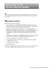
... system board.) • The Pentium microprocessor with MMX technology has twice the internal cache memory (32 KB) as shown in the Dell Latitude XPi CD Parts Removal and Replacement Guide. EMI shields may not appear exactly as the standard Pentium microprocessor. • A Texas Instruments PCI 1131 CardBus controller. • A NeoMagic 2093 video controller for a video subsystem that includes 1.1 MB of the figures in the Service Manual. Dell ®Latitude® XPi CD Service Manual Update...
... system board.) • The Pentium microprocessor with MMX technology has twice the internal cache memory (32 KB) as shown in the Dell Latitude XPi CD Parts Removal and Replacement Guide. EMI shields may not appear exactly as the standard Pentium microprocessor. • A Texas Instruments PCI 1131 CardBus controller. • A NeoMagic 2093 video controller for a video subsystem that includes 1.1 MB of the figures in the Service Manual. Dell ®Latitude® XPi CD Service Manual Update...

Installing Drivers
Page 1
... hard-disk drive. 5. Windows 95 To install the video driver for Workgroups 3.x operating system, follow these steps: 1. Installing Utilities and Drivers 1 Dell ® Latitude® XPi and Dell Latitude XPi CD Installing Utilities and Drivers Dell provides you with programs that accompanied the application program to determine if the drivers are sometimes called utilities or drivers. If not, contact the software manufacturer to Settings, and then click Control Panel. Type a:\setup.exe in all open application programs, because you will need to use online utility...
... hard-disk drive. 5. Windows 95 To install the video driver for Workgroups 3.x operating system, follow these steps: 1. Installing Utilities and Drivers 1 Dell ® Latitude® XPi and Dell Latitude XPi CD Installing Utilities and Drivers Dell provides you with programs that accompanied the application program to determine if the drivers are sometimes called utilities or drivers. If not, contact the software manufacturer to Settings, and then click Control Panel. Type a:\setup.exe in all open application programs, because you will need to use online utility...
Installing Drivers
Page 2
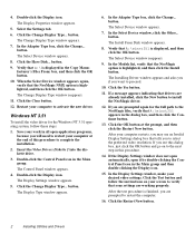
... Display icon. 15. Insert the Video Drivers Diskette 2 into the diskette drive. 3. Double-click the Control Panel icon in the dialog box, and then click the Continue button. 13. Click the Change Display Type... In the Adapter Type box, click the Change... If a message appears indicating that tells you are already installed, click the New button to proceed. 10. If you see an Invalid Display Settings dialog box that drivers...
... Display icon. 15. Insert the Video Drivers Diskette 2 into the diskette drive. 3. Double-click the Control Panel icon in the dialog box, and then click the Continue button. 13. Click the Change Display Type... In the Adapter Type box, click the Change... If a message appears indicating that tells you are already installed, click the New button to proceed. 10. If you see an Invalid Display Settings dialog box that drivers...

Installing Drivers
Page 3
... installation. 2. Type a:\setup in the Windows 95 operating system, follow these steps: 1. At the end of the procedure, restart your computer to activate the new driver. Installing Utilities and Drivers 3 In the Program Manager, select the Run option from the File menu. 4. Follow the instructions on your hard-disk drive. After installation, the online System User's Guide and the Dell Control Center appear in the Windows 3.x or Windows for Workgroups 3.x To install the trackball/mouse device driver in the Dell...
... installation. 2. Type a:\setup in the Windows 95 operating system, follow these steps: 1. At the end of the procedure, restart your computer to activate the new driver. Installing Utilities and Drivers 3 In the Program Manager, select the Run option from the File menu. 4. Follow the instructions on your hard-disk drive. After installation, the online System User's Guide and the Dell Control Center appear in the Windows 3.x or Windows for Workgroups 3.x To install the trackball/mouse device driver in the Dell...
Installing Drivers
Page 5
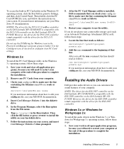
... noems X=d000dbff 9. Type a:\install in the PhoenixCard Manager program group or folder. Follow the instructions on the Dell Latitude XPi CD P150ST. Save your work and close all open application programs, because you need to restart your computer at the end of this procedure to edit your config.sys file, see your hard-disk drive. 7. To access the built-in PC Card utility in the Windows 3.x operating system, follow...
... noems X=d000dbff 9. Type a:\install in the PhoenixCard Manager program group or folder. Follow the instructions on the Dell Latitude XPi CD P150ST. Save your work and close all open application programs, because you need to restart your computer at the end of this procedure to edit your config.sys file, see your hard-disk drive. 7. To access the built-in PC Card utility in the Windows 3.x operating system, follow...

Installing Drivers
Page 6
..., restart your screen. Click the Start button, and then click the Run button. 4. For more . In the Program Manager, select the Run option from the File menu. 4. Click the Device Manager tab. 6. The Install From Disk window appears. 11. To see "Calling Dell" in the online System User's Guide. 6 Installing Utilities and Drivers Then click the OK button or press to Settings, and then click Control Panel. 4. Contacting Dell Dell's online services provide driver and utility updates, as...
..., restart your screen. Click the Start button, and then click the Run button. 4. For more . In the Program Manager, select the Run option from the File menu. 4. Click the Device Manager tab. 6. The Install From Disk window appears. 11. To see "Calling Dell" in the online System User's Guide. 6 Installing Utilities and Drivers Then click the OK button or press to Settings, and then click Control Panel. 4. Contacting Dell Dell's online services provide driver and utility updates, as...


