
Service Manual
Page 3
Contents Chapter 1 System Overview 1-1 System Features 1-1 Physical Description 1-2 Indicator Panel 1-3 Power/Suspend Indicator 1-4 Diskette-Drive Access Indicator 1-4 Hard-Disk/CD-ROM Drive Access Indicator 1-4 PC Card Access Indicator 1-4 Low-Battery Indicator 1-4 Charging Indicator 1-4 Keyboard Indicators 1-5 Controlling Computer Power 1-5 Power States 1-5 Interrupt Assignments 1-6 Technical Specifications 1-7 Chapter 2 Initial Procedures 2-1 ...
Contents Chapter 1 System Overview 1-1 System Features 1-1 Physical Description 1-2 Indicator Panel 1-3 Power/Suspend Indicator 1-4 Diskette-Drive Access Indicator 1-4 Hard-Disk/CD-ROM Drive Access Indicator 1-4 PC Card Access Indicator 1-4 Low-Battery Indicator 1-4 Charging Indicator 1-4 Keyboard Indicators 1-5 Controlling Computer Power 1-5 Power States 1-5 Interrupt Assignments 1-6 Technical Specifications 1-7 Chapter 2 Initial Procedures 2-1 ...
Service Manual
Page 4
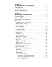
... Beep Codes 3-1 System Error Messages 3-3 Running the Dell Diagnostics 3-8 Chapter 4 Removing and Replacing Parts 4-1 Recommended Tools 4-2 Precautionary Measures 4-2 Screw Identification and Tightening 4-4 ZIF Connectors 4-5 Field-Replaceable Parts and Assemblies 4-6 Hard-Disk Drive Assembly 4-7 Memory Compartment Cover 4-8 Memory Modules 4-9 ...4-25 Display-Assembly Interface Cable 4-26 Microphone/Switch Assembly 4-28 Bottom Case Assembly 4-29 Diskette/CD-ROM Drive Assembly 4-31 Deck Buoy 4-33 Superpart Assembly 4-34 Reserve Battery 4-36 System Board Assembly 4-38 Removing ...
... Beep Codes 3-1 System Error Messages 3-3 Running the Dell Diagnostics 3-8 Chapter 4 Removing and Replacing Parts 4-1 Recommended Tools 4-2 Precautionary Measures 4-2 Screw Identification and Tightening 4-4 ZIF Connectors 4-5 Field-Replaceable Parts and Assemblies 4-6 Hard-Disk Drive Assembly 4-7 Memory Compartment Cover 4-8 Memory Modules 4-9 ...4-25 Display-Assembly Interface Cable 4-26 Microphone/Switch Assembly 4-28 Bottom Case Assembly 4-29 Diskette/CD-ROM Drive Assembly 4-31 Deck Buoy 4-33 Superpart Assembly 4-34 Reserve Battery 4-36 System Board Assembly 4-38 Removing ...

Service Manual
Page 5
... Repair Parts A-1 Recommended Tools A-1 Precautionary Measures A-1 Factory Repair Parts and Assemblies A-1 Exploded Views of Components and Assemblies A-12 Hard-Disk Drive A-15 CD-ROM Drive A-16 Diskette Drive A-16 Palmrest Assembly Components A-16 Trackball A-16 Trackball Interface Cable A-16 Trackball Button Board A-16 Palmrest Brace A-16 Display Assembly... Button and Power-Button Mounting Bracket A-26 Spreader and Keel Plates A-27 Appendix B System Setup Options B-1 Accessing the Dell Control Center B-1 Accessing the System Setup Program B-2 System Setup Screens B-3 vii
... Repair Parts A-1 Recommended Tools A-1 Precautionary Measures A-1 Factory Repair Parts and Assemblies A-1 Exploded Views of Components and Assemblies A-12 Hard-Disk Drive A-15 CD-ROM Drive A-16 Diskette Drive A-16 Palmrest Assembly Components A-16 Trackball A-16 Trackball Interface Cable A-16 Trackball Button Board A-16 Palmrest Brace A-16 Display Assembly... Button and Power-Button Mounting Bracket A-26 Spreader and Keel Plates A-27 Appendix B System Setup Options B-1 Accessing the Dell Control Center B-1 Accessing the System Setup Program B-2 System Setup Screens B-3 vii

Service Manual
Page 6
... Figure 4-16. Back View of the Notebook Computer 1-2 Figure 1-2. Memory Module Removal 4-9 Figure 4-9. Disconnecting an Interface Cable 4-5 Figure 4-5. Hard-Disk Drive Assembly Removal 4-7 Figure 4-7. Tilt-Support Foot Removal 4-16 Figure 4-14. Diskette/CD-ROM Drive Assembly Removal 4-31 Figure 4-24. Index Figures Figure 1-1. System Board Assembly Removal 4-38 Figure 4-28. Front View of...
... Figure 4-16. Back View of the Notebook Computer 1-2 Figure 1-2. Memory Module Removal 4-9 Figure 4-9. Disconnecting an Interface Cable 4-5 Figure 4-5. Hard-Disk Drive Assembly Removal 4-7 Figure 4-7. Tilt-Support Foot Removal 4-16 Figure 4-14. Diskette/CD-ROM Drive Assembly Removal 4-31 Figure 4-24. Index Figures Figure 1-1. System Board Assembly Removal 4-38 Figure 4-28. Front View of...
Service Manual
Page 11
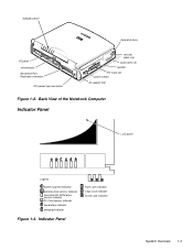
Indicator Panel Num Lock indicator Caps Lock indicator Scroll Lock indicator System Overview 1-3 indicator panel hard-disk drive I/O panel infrared port Advanced Port Replicator connector DC power input connector security cable slot audio jacks (3) speaker PC Card slot power switch tilt-support foot Figure 1-2. Back View of the Notebook Computer Indicator Panel LCD panel Legend power/suspend indicator diskette-drive access indicator hard-disk/CD-ROM drive access indicator PC Card access indicator low-battery indicator charging indicator Figure 1-3.
Indicator Panel Num Lock indicator Caps Lock indicator Scroll Lock indicator System Overview 1-3 indicator panel hard-disk drive I/O panel infrared port Advanced Port Replicator connector DC power input connector security cable slot audio jacks (3) speaker PC Card slot power switch tilt-support foot Figure 1-2. Back View of the Notebook Computer Indicator Panel LCD panel Legend power/suspend indicator diskette-drive access indicator hard-disk/CD-ROM drive access indicator PC Card access indicator low-battery indicator charging indicator Figure 1-3.

Service Manual
Page 12
...to show the battery is fully charged. 1-4 Dell Latitude XPi CD Service Manual The subsections that the computer is being transferred to or from the hard-disk drive or the CD-ROM. Hard-Disk/CD-ROM Drive Access Indicator The hard-disk/CD-ROM drive access indicator is being transferred to or from... the diskette drive. The indicator lights when data is receiving stable power....
...to show the battery is fully charged. 1-4 Dell Latitude XPi CD Service Manual The subsections that the computer is being transferred to or from the hard-disk drive or the CD-ROM. Hard-Disk/CD-ROM Drive Access Indicator The hard-disk/CD-ROM drive access indicator is being transferred to or from... the diskette drive. The indicator lights when data is receiving stable power....

Service Manual
Page 14
... IRQ14 Generated by the keyboard controller to indicate that the output buffer of the microprocessor IRQ15 Reserved for the CD-ROM drive 1-6 Dell Latitude XPi CD Service Manual Interrupt Assignments IRQ Line Used/Available IRQ0 Generated by the system timer IRQ1 Generated by the keyboard controller ...attached IRQ11 Available for use by a PC Card unless the Advanced Port Replicator is attached IRQ12 Generated by the hard-disk drive to indicate that the drive requires the attention of the integrated trackball or external PS/2 mouse is attached, sliding the power button has no...
... IRQ14 Generated by the keyboard controller to indicate that the output buffer of the microprocessor IRQ15 Reserved for the CD-ROM drive 1-6 Dell Latitude XPi CD Service Manual Interrupt Assignments IRQ Line Used/Available IRQ0 Generated by the system timer IRQ1 Generated by the keyboard controller ...attached IRQ11 Available for use by a PC Card unless the Advanced Port Replicator is attached IRQ12 Generated by the hard-disk drive to indicate that the drive requires the attention of the integrated trackball or external PS/2 mouse is attached, sliding the power button has no...

Service Manual
Page 20
... 128 KB Physical (Computer) Height 63.0 mm (2.48 inches) Width 280.9 mm (11.06 inches) Depth 233.5 mm (9.19 inches) Weight (with battery and hard-disk drive 3.29 kg (7.26 lb) Environmental Temperature: Operating 10° to 40°C (50° to 104°F) Storage 40° to 65°C (-40... Operating 0.51 GRMS, using a random-vibration spectrum that simulates truck shipment Storage 1.1 GRMS, using a random-vibration spectrum that simulates air/truck shipment 3 The CD-ROM drive in your computer may have different specifications. 1-12 Dell Latitude XPi CD Service Manual Table 1-2.
... 128 KB Physical (Computer) Height 63.0 mm (2.48 inches) Width 280.9 mm (11.06 inches) Depth 233.5 mm (9.19 inches) Weight (with battery and hard-disk drive 3.29 kg (7.26 lb) Environmental Temperature: Operating 10° to 40°C (50° to 104°F) Storage 40° to 65°C (-40... Operating 0.51 GRMS, using a random-vibration spectrum that simulates truck shipment Storage 1.1 GRMS, using a random-vibration spectrum that simulates air/truck shipment 3 The CD-ROM drive in your computer may have different specifications. 1-12 Dell Latitude XPi CD Service Manual Table 1-2.

Service Manual
Page 21
System Overview 1-13 Technical Specifications (Continued) Environmental (Continued) Maximum shock:4 Operating 152.4 cm/sec (60 inches/sec) (less than or equal to a pulse width of 2 ms) Storage 203.2 cm/sec (80 inches/sec) (less than or equal to a pulse width of 2 ms) Altitude (maximum): Operating 3048 m (10,000 ft) Storage 10,600 m (35,000 ft) 4 Measured with the hard-disk drive in head-parked position. Table 1-2.
System Overview 1-13 Technical Specifications (Continued) Environmental (Continued) Maximum shock:4 Operating 152.4 cm/sec (60 inches/sec) (less than or equal to a pulse width of 2 ms) Storage 203.2 cm/sec (80 inches/sec) (less than or equal to a pulse width of 2 ms) Altitude (maximum): Operating 3048 m (10,000 ft) Storage 10,600 m (35,000 ft) 4 Measured with the hard-disk drive in head-parked position. Table 1-2.

Service Manual
Page 23
.... Can the user duplicate the problem? Ask the user to determine whether he or she is making any data on the hard-disk drive if the system's condition permits. Yes. puter problem. Dell recommends that can help you diagnose a com- A verbal description can often reveal the source of a problem or indicate the correct...
.... Can the user duplicate the problem? Ask the user to determine whether he or she is making any data on the hard-disk drive if the system's condition permits. Yes. puter problem. Dell recommends that can help you diagnose a com- A verbal description can often reveal the source of a problem or indicate the correct...

Service Manual
Page 25
... mouse is free of any obvious physical damage. • The monitor's controls are free of any obvious physical damage, and then reinsert the drive into its keys operate freely. 11. face cable are secure enough to ensure a firm connection. • The attached device and its interface ...is operating from the memory compartment, verify that it is free of any obvious damage, and then reinstall the memory modules. 9. Remove the hard-disk drive, verify that the trackball and its cable are set according to the keyboard/keypad/mouse con- nector on the computer's I /O panel. ...
... mouse is free of any obvious physical damage. • The monitor's controls are free of any obvious physical damage, and then reinsert the drive into its keys operate freely. 11. face cable are secure enough to ensure a firm connection. • The attached device and its interface ...is operating from the memory compartment, verify that it is free of any obvious damage, and then reinstall the memory modules. 9. Remove the hard-disk drive, verify that the trackball and its cable are set according to the keyboard/keypad/mouse con- nector on the computer's I /O panel. ...

Service Manual
Page 26
...To prevent possible damage to light during the boot routine. Turn on any indications of the following: • Diskette-drive and hard-disk drive access indicators - After all periph- These indicators light in response to data being transferred to Table 3-1. erals and ... Proceed to Table 3-2. 2-4 Dell Latitude XPi CD Service Manual No. No further steps are necessary. Observing the Boot Routine After you perform a visual inspection as appropriate. • Beep codes - Insert a diagnostics diskette into the diskette drive. Dell recommends that indicates an error ...
...To prevent possible damage to light during the boot routine. Turn on any indications of the following: • Diskette-drive and hard-disk drive access indicators - After all periph- These indicators light in response to data being transferred to Table 3-1. erals and ... Proceed to Table 3-2. 2-4 Dell Latitude XPi CD Service Manual No. No further steps are necessary. Observing the Boot Routine After you perform a visual inspection as appropriate. • Beep codes - Insert a diagnostics diskette into the diskette drive. Dell recommends that indicates an error ...
Service Manual
Page 31
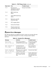
...failure 5-2-4 Setup decompression and shadowing failure System Error Messages The following table lists (in pathname specified. cache memory failed. Data error Diskette or hard-disk drive cannot read the data. Bad command or File Name Command entered does not exist or is not in alphabetical order) system error messages that may...computer operation. System Error Messages Message Definition Probable Causes Auxiliary device failure Integrated trackball or Integrated trackball external PS/2 mouse failed. Faulty diskette/tape drive subsystem or hard-disk drive subsystem.
...failure 5-2-4 Setup decompression and shadowing failure System Error Messages The following table lists (in pathname specified. cache memory failed. Data error Diskette or hard-disk drive cannot read the data. Bad command or File Name Command entered does not exist or is not in alphabetical order) system error messages that may...computer operation. System Error Messages Message Definition Probable Causes Auxiliary device failure Integrated trackball or Integrated trackball external PS/2 mouse failed. Faulty diskette/tape drive subsystem or hard-disk drive subsystem.
Service Manual
Page 113
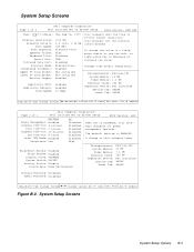
...change values Alt-P next Esc exit Alt-B reboot Page 2 of 2 Dell Computer Corporation Dell Latitude XPi CD System Setup BIOS Version: AXX XXX Time: 13:17:02Date: Mon Feb 12, 1997 Internal Hard Drive: Diskette Drive A: Boot Speed: Boot Sequence: Speaker Volume: Keyboard Click: Serial Port:...-P next Esc exit Alt-B reboot Figure B-3. System Setup Screens System Setup Options B-3 System Setup Screens Page 1 of 2 Dell Computer Corporation Dell Latitude XPi CD System Setup BIOS Version: AXX BATTERY Power Management: Enabled Display Time-Out: 4 minutes Disk Time-Out: 1 minute ...
...change values Alt-P next Esc exit Alt-B reboot Page 2 of 2 Dell Computer Corporation Dell Latitude XPi CD System Setup BIOS Version: AXX XXX Time: 13:17:02Date: Mon Feb 12, 1997 Internal Hard Drive: Diskette Drive A: Boot Speed: Boot Sequence: Speaker Volume: Keyboard Click: Serial Port:...-P next Esc exit Alt-B reboot Figure B-3. System Setup Screens System Setup Options B-3 System Setup Screens Page 1 of 2 Dell Computer Corporation Dell Latitude XPi CD System Setup BIOS Version: AXX BATTERY Power Management: Enabled Display Time-Out: 4 minutes Disk Time-Out: 1 minute ...

Service Manual
Page 114
... DISABLED if a PC Card is installed but not being used. B-4 Dell Latitude XPi CD Service Manual DATE Resets date on computer's internal clock. DISKETTE DRIVE A Identifies type of computer's hard-disk drive. BOOT SPEED Indicates operating frequency at which computer boots-processor's rated speed...release date of PC Card connectors. INFRARED DATA PORT Configures computer's built-in the computer. INTERNAL HARD DRIVE Displays capacity of diskette drive installed. MONITOR TOGGLE Enables key combination that directs where computer's video image is configured as an ...
... DISABLED if a PC Card is installed but not being used. B-4 Dell Latitude XPi CD Service Manual DATE Resets date on computer's internal clock. DISKETTE DRIVE A Identifies type of computer's hard-disk drive. BOOT SPEED Indicates operating frequency at which computer boots-processor's rated speed...release date of PC Card connectors. INFRARED DATA PORT Configures computer's built-in the computer. INTERNAL HARD DRIVE Displays capacity of diskette drive installed. MONITOR TOGGLE Enables key combination that directs where computer's video image is configured as an ...

Reference Guide
Page 12
Display Time-Out 2-7 Expansion Device 2-7 External Cache 2-7 Infrared Data Port 2-7 Integrated Trackball 2-8 IntelliSpin 2-8 Internal Hard Drive 2-8 Keyboard Click 2-8 Lower PC Card Socket and Upper PC Card Socket 2-8 Microprocessor 2-9 Monitor Toggle 2-9 Parallel Mode 2-9 Power Management 2-9 Primary Password 2-10 Replicator Network 2-10 Replicator ...
Display Time-Out 2-7 Expansion Device 2-7 External Cache 2-7 Infrared Data Port 2-7 Integrated Trackball 2-8 IntelliSpin 2-8 Internal Hard Drive 2-8 Keyboard Click 2-8 Lower PC Card Socket and Upper PC Card Socket 2-8 Microprocessor 2-9 Monitor Toggle 2-9 Parallel Mode 2-9 Power Management 2-9 Primary Password 2-10 Replicator Network 2-10 Replicator ...

Reference Guide
Page 28
... reboot key functions computer information Page 2 of 2 title box help Dell Computer Corporation Dell Latitude XPi CD System Setup BIOS Version: AXX XXX Time: 13:17:02 Date: Mon Feb 12, 1997 Internal Hard Drive: 1216 MB Diskette Drive A: 3.5 inch, 1.44 MB Boot Speed: 150 MHz Boot Sequence...of 2 Power Management: Display Time-Out: Disk Time-Out: Suspend Time-Out: S2D Time-Out: Smart CPU Mode: Brightness: Dell Computer Corporation Dell Latitude XPi CD System Setup BIOS Version: AXX BATTERY Enabled 4 minutes 1 minute 10 minutes 8 hours Enabled Low AC Disabled Disabled Disabled Disabled...
... reboot key functions computer information Page 2 of 2 title box help Dell Computer Corporation Dell Latitude XPi CD System Setup BIOS Version: AXX XXX Time: 13:17:02 Date: Mon Feb 12, 1997 Internal Hard Drive: 1216 MB Diskette Drive A: 3.5 inch, 1.44 MB Boot Speed: 150 MHz Boot Sequence...of 2 Power Management: Display Time-Out: Disk Time-Out: Suspend Time-Out: S2D Time-Out: Smart CPU Mode: Brightness: Dell Computer Corporation Dell Latitude XPi CD System Setup BIOS Version: AXX BATTERY Enabled 4 minutes 1 minute 10 minutes 8 hours Enabled Low AC Disabled Disabled Disabled Disabled...

Reference Guide
Page 32
...Card is not properly installed in the connector. 2-8 Dell Latitude XPi CD Reference and Troubleshooting Guide If this option is available for this option are DISABLED (the default) and ENABLED. A change in your computer's hard-disk drive. This option is set to the computer. The... option to COM4. • DISABLED (the default) disables both infrared data ports and their assigned COM addresses. Internal Hard Drive INTERNAL HARD DRIVE displays the capacity of the computer to function. Keyboard Click KEYBOARD CLICK lets you compensate for other serial devices to COM4...
...Card is not properly installed in the connector. 2-8 Dell Latitude XPi CD Reference and Troubleshooting Guide If this option is available for this option are DISABLED (the default) and ENABLED. A change in your computer's hard-disk drive. This option is set to the computer. The... option to COM4. • DISABLED (the default) disables both infrared data ports and their assigned COM addresses. Internal Hard Drive INTERNAL HARD DRIVE displays the capacity of the computer to function. Keyboard Click KEYBOARD CLICK lets you compensate for other serial devices to COM4...

Reference Guide
Page 141
..., 2-8 interchanging, 1-4 power management, 2-6 S2D partition, 2-14 testing, 4-17 troubleshooting, 3-23 Hard-Disk Drives (Non-SCSI) Test Group Dell diagnostics, 4-17 help from Dell Computer Corporation, 5-1 help , 5-1 graphics mode screens, B-4 Graphics Mode Test, B-4 grounding procedure, vi H hard drive. E ECP-compatible devices, 2-9 error messages beep codes, 3-11 Dell diagnostics, 4-12 system error messages, 3-4, 3-5 table, 3-4, 3-5 ESD, viii expanded memory, 3-14...
..., 2-8 interchanging, 1-4 power management, 2-6 S2D partition, 2-14 testing, 4-17 troubleshooting, 3-23 Hard-Disk Drives (Non-SCSI) Test Group Dell diagnostics, 4-17 help from Dell Computer Corporation, 5-1 help , 5-1 graphics mode screens, B-4 Graphics Mode Test, B-4 grounding procedure, vi H hard drive. E ECP-compatible devices, 2-9 error messages beep codes, 3-11 Dell diagnostics, 4-12 system error messages, 3-4, 3-5 table, 3-4, 3-5 ESD, viii expanded memory, 3-14...
Reference Guide
Page 145
... option, 2-7 Expansion Device option, 2-7 External Cache option, 2-7 help messages, 2-3 Infrared Data Port option, 2-7 Integrated Trackball option, 2-8 IntelliSpin option, 2-8 Internal Hard Drive, 2-8 Keyboard Click option, 2-8 Lower PC Card Socket option, 2-8 Microprocessor option, 2-9 Monitor Toggle option, 2-9 options, 2-5 Parallel Mode option, 2-9 Power Management ...repair or credit, 5-4 technical specifications, A-1 terminate-and-stay-resident. See TSR Test Limits option in Dell diagnostics, 4-8 Text Mode Character Test, B-1 Text Mode Color Test, B-3 Text Mode Pages Test, B-4 Index 7
... option, 2-7 Expansion Device option, 2-7 External Cache option, 2-7 help messages, 2-3 Infrared Data Port option, 2-7 Integrated Trackball option, 2-8 IntelliSpin option, 2-8 Internal Hard Drive, 2-8 Keyboard Click option, 2-8 Lower PC Card Socket option, 2-8 Microprocessor option, 2-9 Monitor Toggle option, 2-9 options, 2-5 Parallel Mode option, 2-9 Power Management ...repair or credit, 5-4 technical specifications, A-1 terminate-and-stay-resident. See TSR Test Limits option in Dell diagnostics, 4-8 Text Mode Character Test, B-1 Text Mode Color Test, B-3 Text Mode Pages Test, B-4 Index 7


