Service Manual
Page 3
...-Disk Drive Assembly 7 Keyboard Bezel 8 Display Assembly 9 Display Assembly Bezel 11 Display Assembly Latch 12 LCD Panel 13 Display Assembly Hinges 15 Keyboard Assembly 16 Memory Module 18 Palmrest Assembly 19 Touch Pad Assembly 21 Bottom Assembly 22 Reserve Battery 23 Main Battery 23 Modem 24 Fan 25 Speaker 27 System...
...-Disk Drive Assembly 7 Keyboard Bezel 8 Display Assembly 9 Display Assembly Bezel 11 Display Assembly Latch 12 LCD Panel 13 Display Assembly Hinges 15 Keyboard Assembly 16 Memory Module 18 Palmrest Assembly 19 Touch Pad Assembly 21 Bottom Assembly 22 Reserve Battery 23 Main Battery 23 Modem 24 Fan 25 Speaker 27 System...
Service Manual
Page 4
Keyboard Bezel Removal 8 Figure 8. Memory Module Removal 18 Figure 14. Reserve Battery Removal 23 Figure 19. Speaker Removal 27 Figure 22. Display Assembly Removal 9 Figure 9. Removing the Palmrest Assembly Bottom ...
Keyboard Bezel Removal 8 Figure 8. Memory Module Removal 18 Figure 14. Reserve Battery Removal 23 Figure 19. Speaker Removal 27 Figure 22. Display Assembly Removal 9 Figure 9. Removing the Palmrest Assembly Bottom ...
Service Manual
Page 22
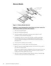
...pop up slightly) (see Figure 13). 5. Align the memory module's edge connector with the slot in only one way. 2. The memory module is notched so that the memory module can be firmly seated only one direction. Memory Module Removal NOTICE: To avoid damaging the system board, you... the memory module socket. With the module at a 45-degree angle, press the memory module's edge connector firmly into the socket in the center of the memory module socket just far enough for the memory module to fit into the memory module socket. 18 Dell Latitude L400 Service Manual Memory Module memory module ...
...pop up slightly) (see Figure 13). 5. Align the memory module's edge connector with the slot in only one way. 2. The memory module is notched so that the memory module can be firmly seated only one direction. Memory Module Removal NOTICE: To avoid damaging the system board, you... the memory module socket. With the module at a 45-degree angle, press the memory module's edge connector firmly into the socket in the center of the memory module socket just far enough for the memory module to fit into the memory module socket. 18 Dell Latitude L400 Service Manual Memory Module memory module ...
Service Manual
Page 23
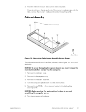
...computer cover. 6. Removing the Palmrest Assembly Bottom Screws The palmrest assembly consists of the memory module snaps into place. Remove the keyboard bezel. 2. NOTICE: Make sure that the work surface. 5. Remove the display assembly. 3. support.dell.com Dell Latitude L400 Service Manual 19 Palmrest Assembly M2.6 x 1.6-mm screws (6) Figure 14. NOTICE: ...mm screws located in the battery bay (see Figure 13). Turn the computer upside down until it clicks into the tabs, remove the memory module and reinstall it (see Figure 14). 3. Turn the computer right-side up.
...computer cover. 6. Removing the Palmrest Assembly Bottom Screws The palmrest assembly consists of the memory module snaps into place. Remove the keyboard bezel. 2. NOTICE: Make sure that the work surface. 5. Remove the display assembly. 3. support.dell.com Dell Latitude L400 Service Manual 19 Palmrest Assembly M2.6 x 1.6-mm screws (6) Figure 14. NOTICE: ...mm screws located in the battery bay (see Figure 13). Turn the computer upside down until it clicks into the tabs, remove the memory module and reinstall it (see Figure 14). 3. Turn the computer right-side up.
Service Manual
Page 27
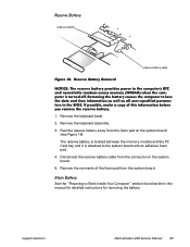
Peel the reserve battery away from the foam pad on the system board. 5. support.dell.com Dell Latitude L400 Service Manual 23 Remove the keyboard assembly. 3. The reserve battery is located between the memory module and the PC Card bay, and it is turned off. If possible, make a copy of ... earlier in the BIOS. Remove the keyboard bezel. 2. Main Battery See the "Preparing to the computer's RTC and nonvolatile random-access memory (NVRAM) when the computer is attached to lose the date and time information as well as all user-specified parameters in this information before...
Peel the reserve battery away from the foam pad on the system board. 5. support.dell.com Dell Latitude L400 Service Manual 23 Remove the keyboard assembly. 3. The reserve battery is located between the memory module and the PC Card bay, and it is turned off. If possible, make a copy of ... earlier in the BIOS. Remove the keyboard bezel. 2. Main Battery See the "Preparing to the computer's RTC and nonvolatile random-access memory (NVRAM) when the computer is attached to lose the date and time information as well as all user-specified parameters in this information before...
Service Manual
Page 35
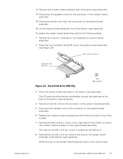
...Reinstall the six M2 x 3.5-mm screws that secure the system board assembly to the connector on the system board assembly. 15. support.dell.com Dell Latitude L400 Service Manual 31 Reconnect the speaker wire to the bottom case assembly. Disconnect the fan wire from the connector on the system board assembly...board assembly. 16. White arrows on the system board assembly point to the connector on the system board assembly (see Figure 23). Transfer the memory module(s) to the system board assembly. The hole for the M2 x 9.5-mm screw is located by the VGA port. 8. Hard-Disk ...
...Reinstall the six M2 x 3.5-mm screws that secure the system board assembly to the connector on the system board assembly. 15. support.dell.com Dell Latitude L400 Service Manual 31 Reconnect the speaker wire to the bottom case assembly. Disconnect the fan wire from the connector on the system board assembly...board assembly. 16. White arrows on the system board assembly point to the connector on the system board assembly (see Figure 23). Transfer the memory module(s) to the system board assembly. The hole for the M2 x 9.5-mm screw is located by the VGA port. 8. Hard-Disk ...
Service Manual
Page 39
Index A APR docking doors removal, 33 B bottom assembly components, 22 illustrated, 22 D display assembly bezel removal, 11 hinge removal, 15 latch removal, 12 removal, 9 F fan removal, 25 field-replaceable parts and assemblies illustrated, 6 G grounding to dissipate static electricity, 3 H hard-disk drive assembly removal, 7 hinge removal, 15 K keyboard assembly removal, 16 L latch removal, 12 LCD panel removal, 13 M main battery release latch removal, 32 removal, 3, 23 memory module removal, 18 modem removal, 24 P palmrest assembly removal, 19 Index 1
Index A APR docking doors removal, 33 B bottom assembly components, 22 illustrated, 22 D display assembly bezel removal, 11 hinge removal, 15 latch removal, 12 removal, 9 F fan removal, 25 field-replaceable parts and assemblies illustrated, 6 G grounding to dissipate static electricity, 3 H hard-disk drive assembly removal, 7 hinge removal, 15 K keyboard assembly removal, 16 L latch removal, 12 LCD panel removal, 13 M main battery release latch removal, 32 removal, 3, 23 memory module removal, 18 modem removal, 24 P palmrest assembly removal, 19 Index 1

System Information Guide
Page 10
... on the computer's I /O connector to remove any of your computer's electronic components, such as a memory module. Just before you touch any static charge your body may have accumulated. If possible, use antistatic floor pads and workbench pads. 1-8 Dell Latitude L400 System Information Guide To prevent static damage, discharge static electricity from your body before...
... on the computer's I /O connector to remove any of your computer's electronic components, such as a memory module. Just before you touch any static charge your body may have accumulated. If possible, use antistatic floor pads and workbench pads. 1-8 Dell Latitude L400 System Information Guide To prevent static damage, discharge static electricity from your body before...


