Service Manual
Page 3
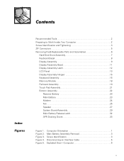
...-Computer 6 v Contents Index Figures Recommended Tools 2 Preparing to Work Inside Your Computer 2 Screw Identification and Tightening 3 ZIF Connectors 5 Removing Field-Replaceable Parts and Assemblies 6 Hard-Disk Drive Assembly 7 Keyboard Bezel 8 Display Assembly 9 Display Assembly Bezel 11 Display Assembly Latch 12 LCD Panel 13 Display Assembly Hinges 15 Keyboard Assembly 16 Memory Module...
...-Computer 6 v Contents Index Figures Recommended Tools 2 Preparing to Work Inside Your Computer 2 Screw Identification and Tightening 3 ZIF Connectors 5 Removing Field-Replaceable Parts and Assemblies 6 Hard-Disk Drive Assembly 7 Keyboard Bezel 8 Display Assembly 9 Display Assembly Bezel 11 Display Assembly Latch 12 LCD Panel 13 Display Assembly Hinges 15 Keyboard Assembly 16 Memory Module...
Service Manual
Page 4
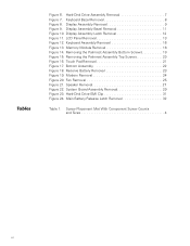
... Palmrest Assembly Bottom Screws 19 Figure 15. Speaker Removal 27 Figure 22. Display Assembly Latch Removal 12 Figure 11. Bottom Assembly 22 Figure 18. Hard-Disk Drive EMI Clip 31 Figure 24. Touch Pad Removal 21 Figure 17. Memory Module Removal 18 Figure 14. Screw Placement Mat With Component Screw Counts and...
... Palmrest Assembly Bottom Screws 19 Figure 15. Speaker Removal 27 Figure 22. Display Assembly Latch Removal 12 Figure 11. Bottom Assembly 22 Figure 18. Hard-Disk Drive EMI Clip 31 Figure 24. Touch Pad Removal 21 Figure 17. Memory Module Removal 18 Figure 14. Screw Placement Mat With Component Screw Counts and...
Service Manual
Page 8
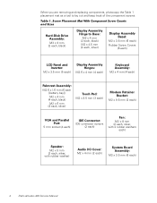
Screw Placement Mat With Component Screw Counts and Sizes Hard-Disk Drive Assembly: M3 x 3 mm (2 each ) 4 Dell Latitude L400 Service Manual When you are removing and replacing components, photocopy the Table 1 placement mat as a tool to Base: M2 x 4 mm (2 each, black) M2 x 4.5 mm (2 each, ...
Screw Placement Mat With Component Screw Counts and Sizes Hard-Disk Drive Assembly: M3 x 3 mm (2 each ) 4 Dell Latitude L400 Service Manual When you are removing and replacing components, photocopy the Table 1 placement mat as a tool to Base: M2 x 4 mm (2 each, black) M2 x 4.5 mm (2 each, ...
Service Manual
Page 10
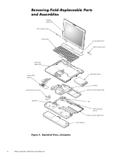
Exploded View-Computer 6 Dell Latitude L400 Service Manual Removing Field-Replaceable Parts and Assemblies display assembly left hinge cover keyboard keyboard bezel right hinge cover palmrest assembly audio EMI shield audio I/O port cover speaker hard-disk drive modem system board assembly fan APR docking doors bottom case assembly main battery Figure 5.
Exploded View-Computer 6 Dell Latitude L400 Service Manual Removing Field-Replaceable Parts and Assemblies display assembly left hinge cover keyboard keyboard bezel right hinge cover palmrest assembly audio EMI shield audio I/O port cover speaker hard-disk drive modem system board assembly fan APR docking doors bottom case assembly main battery Figure 5.
Service Manual
Page 11
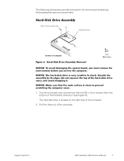
... clean to shock. The following subsections provide instructions for removing and replacing field-replaceable parts and assemblies. support.dell.com Dell Latitude L400 Service Manual 7 Hard-Disk Drive Assembly M3 x 3-mm screws (2) hard-disk drive bottom of the computer. 2. Handle the assembly by its edges (do not squeeze the top of the computer. NOTICE: Make sure that the...
... clean to shock. The following subsections provide instructions for removing and replacing field-replaceable parts and assemblies. support.dell.com Dell Latitude L400 Service Manual 7 Hard-Disk Drive Assembly M3 x 3-mm screws (2) hard-disk drive bottom of the computer. 2. Handle the assembly by its edges (do not squeeze the top of the computer. NOTICE: Make sure that the...
Service Manual
Page 21
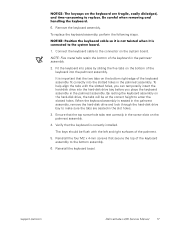
... assembly is important that the keyboard is connected to replace. support.dell.com Dell Latitude L400 Service Manual 17 To replace the keyboard assembly, perform the following steps. It is seated in the palmrest assembly, remove the hard-disk drive and look through the hard-disk drive bay to make sure the tabs are fragile, easily dislodged, and...
... assembly is important that the keyboard is connected to replace. support.dell.com Dell Latitude L400 Service Manual 17 To replace the keyboard assembly, perform the following steps. It is seated in the palmrest assembly, remove the hard-disk drive and look through the hard-disk drive bay to make sure the tabs are fragile, easily dislodged, and...
Service Manual
Page 35
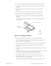
... wire from the bottom case assembly. 14. Place the new hard-disk drive EMI clip on the system board assembly. 15. Reconnect the speaker wire to the screw holes. Reinstall the M2 x 9.5-mm screw on the system board assembly. 6. support.dell.com Dell Latitude L400 Service Manual 31 Remove the modem retainer bracket from the connector...
... wire from the bottom case assembly. 14. Place the new hard-disk drive EMI clip on the system board assembly. 15. Reconnect the speaker wire to the screw holes. Reinstall the M2 x 9.5-mm screw on the system board assembly. 6. support.dell.com Dell Latitude L400 Service Manual 31 Remove the modem retainer bracket from the connector...
Service Manual
Page 36
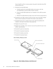
... screws for the VGA and parallel ports located on the back of the M2 x 3.5-mm screws passes through the hard-disk drive EMI clip (see Figure 23). 9. Replace the two M2 x 4-mm screws to secure the audio I /O cover. 13. Reinstall the display assembly. 17. Main Battery Release Latch Removal 32 Dell Latitude L400 Service Manual
... screws for the VGA and parallel ports located on the back of the M2 x 3.5-mm screws passes through the hard-disk drive EMI clip (see Figure 23). 9. Replace the two M2 x 4-mm screws to secure the audio I /O cover. 13. Reinstall the display assembly. 17. Main Battery Release Latch Removal 32 Dell Latitude L400 Service Manual
Service Manual
Page 37
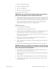
... other . Grasping both doors together, carefully slip the left hinge pins. Remove the keyboard bezel. 2. 1. The APR docking doors should be removed together. 6. support.dell.com Dell Latitude L400 Service Manual 33 To remove the battery release latch, unhook the small tension spring located on the back of the release button together and grasp... the door edge with the screwdriver. 8. Gently push the screw driver against the right edge of the back door to cause the door to the hard-disk drive. Remove the system board.
... other . Grasping both doors together, carefully slip the left hinge pins. Remove the keyboard bezel. 2. 1. The APR docking doors should be removed together. 6. support.dell.com Dell Latitude L400 Service Manual 33 To remove the battery release latch, unhook the small tension spring located on the back of the release button together and grasp... the door edge with the screwdriver. 8. Gently push the screw driver against the right edge of the back door to cause the door to the hard-disk drive. Remove the system board.
Service Manual
Page 39
Index A APR docking doors removal, 33 B bottom assembly components, 22 illustrated, 22 D display assembly bezel removal, 11 hinge removal, 15 latch removal, 12 removal, 9 F fan removal, 25 field-replaceable parts and assemblies illustrated, 6 G grounding to dissipate static electricity, 3 H hard-disk drive assembly removal, 7 hinge removal, 15 K keyboard assembly removal, 16 L latch removal, 12 LCD panel removal, 13 M main battery release latch removal, 32 removal, 3, 23 memory module removal, 18 modem removal, 24 P palmrest assembly removal, 19 Index 1
Index A APR docking doors removal, 33 B bottom assembly components, 22 illustrated, 22 D display assembly bezel removal, 11 hinge removal, 15 latch removal, 12 removal, 9 F fan removal, 25 field-replaceable parts and assemblies illustrated, 6 G grounding to dissipate static electricity, 3 H hard-disk drive assembly removal, 7 hinge removal, 15 K keyboard assembly removal, 16 L latch removal, 12 LCD panel removal, 13 M main battery release latch removal, 32 removal, 3, 23 memory module removal, 18 modem removal, 24 P palmrest assembly removal, 19 Index 1
System Information Guide
Page 5
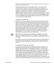
... Always read these options in all regions. • The User's Guide, which is not available in your Dell computer. Other Documents Available The following documents: • Documentation updates, which provides step-by-step instructions for ..., instructions on installing and configuring drivers and utilities, information on your hard-disk drive. support.dell.com Dell Latitude L400 System Information Guide 1-3 Dell™ Latitude™ L400 System Information Guide Your Dell Latitude computer accessories box includes a reduced set of the following documents are ...
... Always read these options in all regions. • The User's Guide, which is not available in your Dell computer. Other Documents Available The following documents: • Documentation updates, which provides step-by-step instructions for ..., instructions on installing and configuring drivers and utilities, information on your hard-disk drive. support.dell.com Dell Latitude L400 System Information Guide 1-3 Dell™ Latitude™ L400 System Information Guide Your Dell Latitude computer accessories box includes a reduced set of the following documents are ...
System Information Guide
Page 7
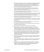
... the cable used with the modem should be ready to turn on the computer. • When traveling with the hard-disk drive removed from the computer, wrap the drive in a nonconducting material, such as cloth or paper. If you must use an extension cable, use a three-...cable during normal operation. You can put the hard-disk drive through a metal detector. • When traveling, do not place the computer in the computer. support.dell.com Dell Latitude L400 System Information Guide 1-5 These cables are asked to install the drive in overhead storage compartments where it could slide ...
... the cable used with the modem should be ready to turn on the computer. • When traveling with the hard-disk drive removed from the computer, wrap the drive in a nonconducting material, such as cloth or paper. If you must use an extension cable, use a three-...cable during normal operation. You can put the hard-disk drive through a metal detector. • When traveling, do not place the computer in the computer. support.dell.com Dell Latitude L400 System Information Guide 1-5 These cables are asked to install the drive in overhead storage compartments where it could slide ...
System Information Guide
Page 14
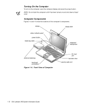
display display latch status indicator panel power button media bay cable integrated microphone external media bay touch pad and buttons Figure 1-4. Front View of the computer's components. NOTE: Do not dock the computer until it has been turned on the computer, open the computer display and press the power button. Computer Components Figures 1-4 and 1-5 show the locations of Computer PC Card slot hard-disk drive security cable slot 1-12 Dell Latitude L400 System Information Guide Turning On the Computer To turn on and shut down at least once.
display display latch status indicator panel power button media bay cable integrated microphone external media bay touch pad and buttons Figure 1-4. Front View of the computer's components. NOTE: Do not dock the computer until it has been turned on the computer, open the computer display and press the power button. Computer Components Figures 1-4 and 1-5 show the locations of Computer PC Card slot hard-disk drive security cable slot 1-12 Dell Latitude L400 System Information Guide Turning On the Computer To turn on and shut down at least once.
System Information Guide
Page 31
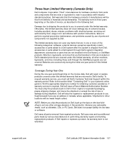
... repairs and building replacement products. Dell may provide replacement parts made by various manufacturers when supplying parts support.dell.com Dell Latitude L400 System Information Guide 1-29 accessories or... parts added to find the appropriate telephone number for obtaining customer assistance. or DellWare™ products. Remove any items that a part should be made freight collect. Dell will be replaced and to Dell. Replacement parts are in one -year period beginning on the hard-disk drive...
... repairs and building replacement products. Dell may provide replacement parts made by various manufacturers when supplying parts support.dell.com Dell Latitude L400 System Information Guide 1-29 accessories or... parts added to find the appropriate telephone number for obtaining customer assistance. or DellWare™ products. Remove any items that a part should be made freight collect. Dell will be replaced and to Dell. Replacement parts are in one -year period beginning on the hard-disk drive...
System Information Guide
Page 33
...manufactures will be made by Dell. The warranty term is three years beginning on the hard-disk drive(s) and any other storage device(s) in one or more of loss or damage during the initial one -year period beginning on Dell's standard price list are...defects in the following categories: software; You must call Dell's Customer Technical Support within the warranty period. Dell owns all other locations will issue a Return Material Authorization Number. support.dell.com Dell Latitude L400 System Information Guide 1-31 Dell uses new and reconditioned parts made freight collect. all...
...manufactures will be made by Dell. The warranty term is three years beginning on the hard-disk drive(s) and any other storage device(s) in one or more of loss or damage during the initial one -year period beginning on Dell's standard price list are...defects in the following categories: software; You must call Dell's Customer Technical Support within the warranty period. Dell owns all other locations will issue a Return Material Authorization Number. support.dell.com Dell Latitude L400 System Information Guide 1-31 Dell uses new and reconditioned parts made freight collect. all...
Advanced Port Replicator User's Guide
Page 27
... of loss or damage during the initial one -year period beginning on the invoice date, Dell will ship parts (freight prepaid) if you ship the product(s) to Dell, back up the data on the hard-disk drive(s) and any removable media, such as diskettes, CDs, or PC Cards. Remove any other... for a replacement part is the remainder of the exchange, replacement parts for replacement parts if the replaced part is not extended. support.dell.com Dell Latitude L400 Advanced Port Replicator User's Guide 1-25 Coverage During Years Two and Three During the second and third years of the exchange...
... of loss or damage during the initial one -year period beginning on the invoice date, Dell will ship parts (freight prepaid) if you ship the product(s) to Dell, back up the data on the hard-disk drive(s) and any removable media, such as diskettes, CDs, or PC Cards. Remove any other... for a replacement part is the remainder of the exchange, replacement parts for replacement parts if the replaced part is not extended. support.dell.com Dell Latitude L400 Advanced Port Replicator User's Guide 1-25 Coverage During Years Two and Three During the second and third years of the exchange...
Advanced Port Replicator User's Guide
Page 29
.... Remove any items that are included on the hard-disk drive(s) and any other locations will issue a Return Material Authorization Number. If Dell repairs or replaces a product, its warranty term is required, Dell will be made freight collect. Dell may provide Dell Latitude L400 Advanced Port Replicator User's Guide 1-27 Dell uses new and reconditioned parts made freight collect...
.... Remove any items that are included on the hard-disk drive(s) and any other locations will issue a Return Material Authorization Number. If Dell repairs or replaces a product, its warranty term is required, Dell will be made freight collect. Dell may provide Dell Latitude L400 Advanced Port Replicator User's Guide 1-27 Dell uses new and reconditioned parts made freight collect...


