Service Manual
Page 3
Dell™ Latitude™ E6400 XFR Service Manual Table of Contents 1 TROUBLESHOOTING...7 1.1 TROUBLESHOOTING TOOLS ...7 1.1.1 Diagnostic Lights...7 1.1.2 Hardware Troubleshooter ...8 1.1.3 Dell Diagnostics ...8 1.1.4 Error Messages ...12 1.2 SOLVING PROBLEMS...12 1.2.1 Battery Problems ...13 1.2.2 Drive Problems...13 1.2.3 IEEE 1394 Device Problems...14 1.2.4 Lockups and Software Problems ...14 1.2.5 Memory Problems ...16 1.2.6 Power Problems ...16 1.2.7 Sound and Speaker Problems......
Dell™ Latitude™ E6400 XFR Service Manual Table of Contents 1 TROUBLESHOOTING...7 1.1 TROUBLESHOOTING TOOLS ...7 1.1.1 Diagnostic Lights...7 1.1.2 Hardware Troubleshooter ...8 1.1.3 Dell Diagnostics ...8 1.1.4 Error Messages ...12 1.2 SOLVING PROBLEMS...12 1.2.1 Battery Problems ...13 1.2.2 Drive Problems...13 1.2.3 IEEE 1394 Device Problems...14 1.2.4 Lockups and Software Problems ...14 1.2.5 Memory Problems ...16 1.2.6 Power Problems ...16 1.2.7 Sound and Speaker Problems......
Service Manual
Page 4
Dell™ Latitude™ E6400 XFR Service Manual 9.2 REPLACING THE RF PASSTHRU BOARD ...31 10 FAN ASSEMBLY ...32 10.1 REMOVING THE FAN ASSEMBLY ...32 10.2 REPLACING THE FAN ASSEMBLY ...33 11 ... PROCESSOR MODULE ...35 13 MEMORY ...36 13.1 REMOVING A MEMORY MODULE ...37 13.2 REPLACING A MEMORY MODULE...37 14 COIN-CELL BATTERY ...38 14.1 REMOVING THE COIN-CELL BATTERY ...38 14.2 REPLACING THE COIN-CELL BATTERY...38 15 LED COVER ...39 15.1 REMOVING THE LED COVER ...39 15.2 REPLACING THE LED COVER ...40 16 PALM...
Dell™ Latitude™ E6400 XFR Service Manual 9.2 REPLACING THE RF PASSTHRU BOARD ...31 10 FAN ASSEMBLY ...32 10.1 REMOVING THE FAN ASSEMBLY ...32 10.2 REPLACING THE FAN ASSEMBLY ...33 11 ... PROCESSOR MODULE ...35 13 MEMORY ...36 13.1 REMOVING A MEMORY MODULE ...37 13.2 REPLACING A MEMORY MODULE...37 14 COIN-CELL BATTERY ...38 14.1 REMOVING THE COIN-CELL BATTERY ...38 14.2 REPLACING THE COIN-CELL BATTERY...38 15 LED COVER ...39 15.1 REMOVING THE LED COVER ...39 15.2 REPLACING THE LED COVER ...40 16 PALM...
Service Manual
Page 6
Dell™ Latitude™ E6400 XFR Service Manual 36.1 REMOVING THE HANDLE...65 36.2 REPLACING THE HANDLE ...65 37 DOORS ...66 37.1 REMOVING MEDIA BAY DOOR ...66 37.2 REPLACING MEDIA BAY ... 37.6 REPLACING THE AV PANEL COVER...68 37.7 REMOVING THE RJ11 DOOR...68 37.8 REPLACING THE RJ11 DOOR...69 37.9 REMOVING THE BATTERY DOOR ...69 37.10 REPLACING THE BATTERY DOOR ...70 37.11 REMOVING THE POWER DOOR...70 37.12 REPLACING THE POWER DOOR ...71 37.13 REMOVING THE VGA DOOR...
Dell™ Latitude™ E6400 XFR Service Manual 36.1 REMOVING THE HANDLE...65 36.2 REPLACING THE HANDLE ...65 37 DOORS ...66 37.1 REMOVING MEDIA BAY DOOR ...66 37.2 REPLACING MEDIA BAY ... 37.6 REPLACING THE AV PANEL COVER...68 37.7 REMOVING THE RJ11 DOOR...68 37.8 REPLACING THE RJ11 DOOR...69 37.9 REMOVING THE BATTERY DOOR ...69 37.10 REPLACING THE BATTERY DOOR ...70 37.11 REMOVING THE POWER DOOR...70 37.12 REPLACING THE POWER DOOR ...71 37.13 REMOVING THE VGA DOOR...
Service Manual
Page 13
.... Windows Vista: Click the Windows Vista Start button and click Computer. TURN OFF STANDBY MODE IN WINDOWS BEFORE WRITING TO A DISC - Dell™ Latitude™ E6400 XFR Service Manual 1.2.1 Battery Problems CAUTION: There is a danger of a new battery exploding if it up by clicking the slidebar and dragging it is not muted by the manufacturer.
.... Windows Vista: Click the Windows Vista Start button and click Computer. TURN OFF STANDBY MODE IN WINDOWS BEFORE WRITING TO A DISC - Dell™ Latitude™ E6400 XFR Service Manual 1.2.1 Battery Problems CAUTION: There is a danger of a new battery exploding if it up by clicking the slidebar and dragging it is not muted by the manufacturer.
Service Manual
Page 19
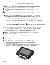
...their electrical outlets. Page 19 NOTICE: To avoid electrostatic discharge, ground yourself by Dell is flat and clean to turn off and not in the unlocked position. 8. Open the rear battery door by its strain-relief loop, not on your warranty. Turn the computer... Slide the battery release latches toward each other to the connector and/or the connector's pins. 1. If you service the computer. NOTICE: To disconnect a network cable, first unplug the cable from your computer and all attached devices from the computer. Dell™ Latitude™ E6400 XFR Service Manual...
...their electrical outlets. Page 19 NOTICE: To avoid electrostatic discharge, ground yourself by Dell is flat and clean to turn off and not in the unlocked position. 8. Open the rear battery door by its strain-relief loop, not on your warranty. Turn the computer... Slide the battery release latches toward each other to the connector and/or the connector's pins. 1. If you service the computer. NOTICE: To disconnect a network cable, first unplug the cable from your computer and all attached devices from the computer. Dell™ Latitude™ E6400 XFR Service Manual...
Service Manual
Page 20
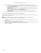
... Dell computer. Do not use only the battery designed for other Dell computers. 1. Turn on your computer and all attached devices to ground the system board. 2.3 After Working On Your Computer After you have completed the replacement procedures, ensure you connect the external devices, cards, cables, etc. Dell™ Latitude™ E6400 XFR Service Manual 9. Replace the battery...
... Dell computer. Do not use only the battery designed for other Dell computers. 1. Turn on your computer and all attached devices to ground the system board. 2.3 After Working On Your Computer After you have completed the replacement procedures, ensure you connect the external devices, cards, cables, etc. Dell™ Latitude™ E6400 XFR Service Manual 9. Replace the battery...
Service Manual
Page 23
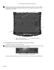
... this gasket might provide some resistance during removal. 3 2 1 1 M2.5 x 5mm screws (21) 2 Bottom of computer 3 Battery release slider latches (2) 4.2 Replacing the Bottom Access Panel 1. Dell™ Latitude™ E6400 XFR Service Manual NOTE: No snaps are in their locked positions. Battery release latches in the sequence identified below for correct slider latches positions. Page 23 Position...
... this gasket might provide some resistance during removal. 3 2 1 1 M2.5 x 5mm screws (21) 2 Bottom of computer 3 Battery release slider latches (2) 4.2 Replacing the Bottom Access Panel 1. Dell™ Latitude™ E6400 XFR Service Manual NOTE: No snaps are in their locked positions. Battery release latches in the sequence identified below for correct slider latches positions. Page 23 Position...

Service Manual
Page 38
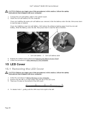
... Properties → General. In Windows Vista, click Start → Help and Support→ Dell System Information. 14 Coin-Cell Battery 14.1 Removing the Coin-Cell Battery CAUTION: Before you begin any of the computer. 4. Follow the procedures in After Working on your computer... the Bottom Access Panel). 4. To confirm the amount of the coin-cell battery, and then lift it detects the additional memory and automatically updates the system configuration information. Dell™ Latitude™ E6400 XFR Service Manual 1 Tab 2 Notch 3. Follow the procedures in Before Working on...
... Properties → General. In Windows Vista, click Start → Help and Support→ Dell System Information. 14 Coin-Cell Battery 14.1 Removing the Coin-Cell Battery CAUTION: Before you begin any of the computer. 4. Follow the procedures in After Working on your computer... the Bottom Access Panel). 4. To confirm the amount of the coin-cell battery, and then lift it detects the additional memory and automatically updates the system configuration information. Dell™ Latitude™ E6400 XFR Service Manual 1 Tab 2 Notch 3. Follow the procedures in Before Working on...
Service Manual
Page 39
... your computer. 1. If you removed, slide the battery under the tab, then press down to the left. Follow the procedures in Before Working on the bottom of the LED cover. 1 2 3 4 5 4. Dell™ Latitude™ E6400 XFR Service Manual CAUTION: Before you begin any of the... procedures in this section, follow the safety instructions that shipped with your computer. 1. Insert the coin-cell battery into the computer: If you are installing the same...
... your computer. 1. If you removed, slide the battery under the tab, then press down to the left. Follow the procedures in Before Working on the bottom of the LED cover. 1 2 3 4 5 4. Dell™ Latitude™ E6400 XFR Service Manual CAUTION: Before you begin any of the... procedures in this section, follow the safety instructions that shipped with your computer. 1. Insert the coin-cell battery into the computer: If you are installing the same...
Service Manual
Page 54
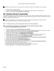
... cable channel covers, display assembly, LED cover, palm rest overlay, keyboard, and palm rest and smartcard assembly (see Removing the Coin Cell Battery). 5. Remove the coin-cell battery (see Removing the Palm Rest). 3. Remove any of the computer. Remove the memory modules (see Chapter 5, 6, 7 and 8 for... the two M2 x 3-mm screws that shipped with your computer. 1. Disconnect the 1394 cable from the system board. 13. Dell™ Latitude™ E6400 XFR Service Manual NOTE: The security screw on the modular drive is also visible on a barcode label on the bottom of the procedures...
... cable channel covers, display assembly, LED cover, palm rest overlay, keyboard, and palm rest and smartcard assembly (see Removing the Coin Cell Battery). 5. Remove the coin-cell battery (see Removing the Palm Rest). 3. Remove any of the computer. Remove the memory modules (see Chapter 5, 6, 7 and 8 for... the two M2 x 3-mm screws that shipped with your computer. 1. Disconnect the 1394 cable from the system board. 13. Dell™ Latitude™ E6400 XFR Service Manual NOTE: The security screw on the modular drive is also visible on a barcode label on the bottom of the procedures...
Service Manual
Page 56
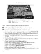
... cable to the connector on the system board. 11. Replace the eight M2.5 x 5-mm screws to the system board. 10. Page 56 Dell™ Latitude™ E6400 XFR Service Manual 1 JSC1 Smartcard connector 5 JBIO1 BIO reader connector 2 JTP1 Touchpad connector 6 J1394 1394 cable connector 3 JSNIF1 Wi-Fi sniffer connector...cables do not get caught beneath the system board. 1. Replace the SIM card assembly (see Replacing the Coin Cell Battery). 19. Replace the coin cell battery (see Replacing the SIM Card Assembly). 12. Route and connect the 1394 card cable to the bottom of the procedures...
... cable to the connector on the system board. 11. Replace the eight M2.5 x 5-mm screws to the system board. 10. Page 56 Dell™ Latitude™ E6400 XFR Service Manual 1 JSC1 Smartcard connector 5 JBIO1 BIO reader connector 2 JTP1 Touchpad connector 6 J1394 1394 cable connector 3 JSNIF1 Wi-Fi sniffer connector...cables do not get caught beneath the system board. 1. Replace the SIM card assembly (see Replacing the Coin Cell Battery). 19. Replace the coin cell battery (see Replacing the SIM Card Assembly). 12. Route and connect the 1394 card cable to the bottom of the procedures...

Service Manual
Page 59
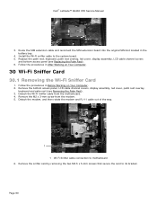
... After Working on Your Computer. 2. Detach the tape and SIM card extension cable from the original SIM slot located on the left side of the battery bay, and place it . 2 1 3 1 Original SIM card slot 2 Wi-Fi sniffer cable connection 3 SIM card board 29.2 Replacing the SIM ...procedures in this section, follow the safety instructions that shipped with your computer. 1. Lift the SIM card slot up . Page 59 Dell™ Latitude™ E6400 XFR Service Manual 28.2 Replacing the 1394 Card CAUTION: Before you begin any of the procedures in this section, follow the safety instructions ...
... After Working on Your Computer. 2. Detach the tape and SIM card extension cable from the original SIM slot located on the left side of the battery bay, and place it . 2 1 3 1 Original SIM card slot 2 Wi-Fi sniffer cable connection 3 SIM card board 29.2 Replacing the SIM ...procedures in this section, follow the safety instructions that shipped with your computer. 1. Lift the SIM card slot up . Page 59 Dell™ Latitude™ E6400 XFR Service Manual 28.2 Replacing the 1394 Card CAUTION: Before you begin any of the procedures in this section, follow the safety instructions ...
Service Manual
Page 60
... extension cable and reconnect the SIM extension board into the original SIM slot located in the battery bay. 4. Install the Wi-Fi sniffer cable to motherboard 6. Remove the M2 x 3-mm screw from the motherboard. 4. Dell™ Latitude™ E6400 XFR Service Manual 3. Replace the palm rest, keyboard, palm rest overlay, led cover, display assembly, LCD...
... extension cable and reconnect the SIM extension board into the original SIM slot located in the battery bay. 4. Install the Wi-Fi sniffer cable to motherboard 6. Remove the M2 x 3-mm screw from the motherboard. 4. Dell™ Latitude™ E6400 XFR Service Manual 3. Replace the palm rest, keyboard, palm rest overlay, led cover, display assembly, LCD...

Service Manual
Page 69
... base assembly 37.8 Replacing the RJ11 Door 1. Follow the procedures in Before Working on Your Computer. 37.9 Removing the Battery Door 1. Follow the procedures in Before Working on Your Computer. 2. Dell™ Latitude™ E6400 XFR Service Manual 1 2 1 Door 2 M2.5 x 5-mm (2) 1. Open the door to relieve hinge pressure. 3. Remove the four M3 x 3-mm screws from...
... base assembly 37.8 Replacing the RJ11 Door 1. Follow the procedures in Before Working on Your Computer. 37.9 Removing the Battery Door 1. Follow the procedures in Before Working on Your Computer. 2. Dell™ Latitude™ E6400 XFR Service Manual 1 2 1 Door 2 M2.5 x 5-mm (2) 1. Open the door to relieve hinge pressure. 3. Remove the four M3 x 3-mm screws from...
Service Manual
Page 70
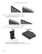
Follow the procedures in After Working on Your Computer. 2. Follow the procedures in Before Working on Your Computer. 37.11 Removing the Power Door Parts Location 1 2 1 Door 2 M2.5 x 5-mm (2) 1. Remove the two M2.5 x 5-mm screws from the bottom of the base assembly Page 70 Dell™ Latitude™ E6400 XFR Service Manual 37.10 Replacing the Battery Door 1. Insert door hinge onto assembly and align the hinge divots. 2. Replace the four M3 x 3-mm screws. 3. Open the door to relieve hinge pressure. 3.
Follow the procedures in After Working on Your Computer. 2. Follow the procedures in Before Working on Your Computer. 37.11 Removing the Power Door Parts Location 1 2 1 Door 2 M2.5 x 5-mm (2) 1. Remove the two M2.5 x 5-mm screws from the bottom of the base assembly Page 70 Dell™ Latitude™ E6400 XFR Service Manual 37.10 Replacing the Battery Door 1. Insert door hinge onto assembly and align the hinge divots. 2. Replace the four M3 x 3-mm screws. 3. Open the door to relieve hinge pressure. 3.
Setup and Features Information Tech Sheet
Page 3
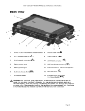
Dell™ Latitude™ E6400 XFR Setup and Features Information Back View 1 2 3 4 5 6 7 8 9 1 PR-481™ Ultra-Performance Chassis Material 8 Security cable slot ( ) 14 11 10 13 12 2 RJ-11 modem connector ( ) 9 Video connector ( ) 3 RJ-45 network connector ( ) 4 Battery access panel 5 Battery/power lights 10 eSATA/USB connector ( ) 11 USB .... Page 3 The computer turns on the fan when the computer gets hot. Do not store your Dell™ computer in the air vents. Fan noise is running. Restricting the airflow can damage the computer or cause a fire.
Dell™ Latitude™ E6400 XFR Setup and Features Information Back View 1 2 3 4 5 6 7 8 9 1 PR-481™ Ultra-Performance Chassis Material 8 Security cable slot ( ) 14 11 10 13 12 2 RJ-11 modem connector ( ) 9 Video connector ( ) 3 RJ-45 network connector ( ) 4 Battery access panel 5 Battery/power lights 10 eSATA/USB connector ( ) 11 USB .... Page 3 The computer turns on the fan when the computer gets hot. Do not store your Dell™ computer in the air vents. Fan noise is running. Restricting the airflow can damage the computer or cause a fire.

Setup and Features Information Tech Sheet
Page 4
Dell™ Latitude™ E6400 XFR Setup and Features Information Bottom View 3 1 2 1 Sealed QuadCool™ thermal management 3 Battery release latches 2 Sliding cover to work with your computer. Do not use a battery from the computer. WARNING: Before removing or replacing the battery, turn off the computer, disconnect the AC adapter from the electrical outlet and the computer, disconnect the...
Dell™ Latitude™ E6400 XFR Setup and Features Information Bottom View 3 1 2 1 Sealed QuadCool™ thermal management 3 Battery release latches 2 Sliding cover to work with your computer. Do not use a battery from the computer. WARNING: Before removing or replacing the battery, turn off the computer, disconnect the AC adapter from the electrical outlet and the computer, disconnect the...

Setup and Features Information Tech Sheet
Page 5
Lower the rear panel. This releases the battery locks. b. b a 2. NOTE: See the battery removal instructions adhered to its unlocked position. Page 5 a. Then, press the latch down. Push the latch to the right, to the edge of the computer. With the battery door open, press in the two battery release latches on the bottom of the battery. 3. Release the rear panel. Dell™ Latitude™ E6400 XFR Setup and Features Information 1.
Lower the rear panel. This releases the battery locks. b. b a 2. NOTE: See the battery removal instructions adhered to its unlocked position. Page 5 a. Then, press the latch down. Push the latch to the right, to the edge of the computer. With the battery door open, press in the two battery release latches on the bottom of the battery. 3. Release the rear panel. Dell™ Latitude™ E6400 XFR Setup and Features Information 1.

Setup and Features Information Tech Sheet
Page 6
Dell™ Latitude™ E6400 XFR Setup and Features Information 4. Hard Drive Removal 1. Insert battery until you hear a click and a mechanical stop. 2. Open the hard drive access door located on the edge of the computer, Page 6 Ensure the door is in the fully closed and locked position. Use the tab on the left side panel by pushing the latch towards the rear of the battery to remove the battery from the computer. Rotate the door into place and push shut. 3. Battery Installation 1.
Dell™ Latitude™ E6400 XFR Setup and Features Information 4. Hard Drive Removal 1. Insert battery until you hear a click and a mechanical stop. 2. Open the hard drive access door located on the edge of the computer, Page 6 Ensure the door is in the fully closed and locked position. Use the tab on the left side panel by pushing the latch towards the rear of the battery to remove the battery from the computer. Rotate the door into place and push shut. 3. Battery Installation 1.

Setup and Features Information Tech Sheet
Page 18
Video NOTE: Your Dell™ computer has both integrated and discrete video options. Video type Integrated and discrete on system board, hardware accelerated Data bus Integrated video or PCI-... Page 18 For more system memory - Windows Vista®) Display Input Primary Storage Battery Discrete video: 256 MB dedicated memory 14.1" Premium WXGA (1280 x 800) wide-aspect transmissive display with 4GB or more system memory - Dell™ Latitude™ E6400 XFR Setup and Features Information Specifications NOTE: Offerings may vary by region. Microsoft® Windows...
Video NOTE: Your Dell™ computer has both integrated and discrete video options. Video type Integrated and discrete on system board, hardware accelerated Data bus Integrated video or PCI-... Page 18 For more system memory - Windows Vista®) Display Input Primary Storage Battery Discrete video: 256 MB dedicated memory 14.1" Premium WXGA (1280 x 800) wide-aspect transmissive display with 4GB or more system memory - Dell™ Latitude™ E6400 XFR Setup and Features Information Specifications NOTE: Offerings may vary by region. Microsoft® Windows...

