User Manual
Page 6
USB Connector 4. Figure 8. For more information regarding the configuration of your computer, click Start → Help and Support and select the option to view information about your computer at least once before you turn on and shut down your computer. The following specifications ...
USB Connector 4. Figure 8. For more information regarding the configuration of your computer, click Start → Help and Support and select the option to view information about your computer at least once before you turn on and shut down your computer. The following specifications ...
User Manual
Page 8
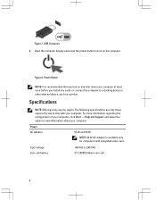
... for additional information on your product is available at support.dell.com/manuals. only) • End User License Agreement Additional information on : • Warranty • Terms and Conditions (U.S. Trademarks used in this text: Dell™, the DELL logo, Dell Precision™, Precision ON™, ExpressCharge™, Latitude™, Latitude ON™, OptiPlex™, Vostro™, and Wi...
... for additional information on your product is available at support.dell.com/manuals. only) • End User License Agreement Additional information on : • Warranty • Terms and Conditions (U.S. Trademarks used in this text: Dell™, the DELL logo, Dell Precision™, Precision ON™, ExpressCharge™, Latitude™, Latitude ON™, OptiPlex™, Vostro™, and Wi...
Statement of Volatility
Page 2
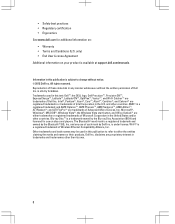
...for external data Remedial Action (Action necessary to clarify memory volatility and data retention in situations where the system is put in the system supports S3 state. see uses system graphics systems. UMA uses next column DDR3. CD- DVD/ DVD+RW/ Diskette Drives Enter S3-S5 ...of main graphics memory. The restore file has to be able to go to disk" state or "hibernate" mode. Dell systems will be valid. No memory - Dell systems will be able to go to a non-volatile storage file and leave appropriate context markers. Description Reference Designator Volatility...
...for external data Remedial Action (Action necessary to clarify memory volatility and data retention in situations where the system is put in the system supports S3 state. see uses system graphics systems. UMA uses next column DDR3. CD- DVD/ DVD+RW/ Diskette Drives Enter S3-S5 ...of main graphics memory. The restore file has to be able to go to disk" state or "hibernate" mode. Dell systems will be valid. No memory - Dell systems will be able to go to a non-volatile storage file and leave appropriate context markers. Description Reference Designator Volatility...
Statement of Volatility
Page 3
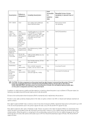
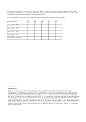
and other countries. in this text: Dell™, the DELL logo, Dell Precision™, OptiPlex™, Latitude™, PowerEdge™, PowerVault™, PowerConnect™, OpenManage™, EqualLogic™...which clears all the states supported by Dell Latitude™ E6230/E6330/E6430/E6430ATG/E6530 Model Number Dell Latitude™ E6230 Dell Latitude™ E6330 Dell Latitude™ E6430 Dell Latitude™ E6530 Dell Latitude™ E6430 ATG S0 S1 S3 S4 S5 X X X X X X X X X X X X X X X X X X X X © 2012 Dell Inc. Red Hat Enterprise Linux...
and other countries. in this text: Dell™, the DELL logo, Dell Precision™, OptiPlex™, Latitude™, PowerEdge™, PowerVault™, PowerConnect™, OpenManage™, EqualLogic™...which clears all the states supported by Dell Latitude™ E6230/E6330/E6430/E6430ATG/E6530 Model Number Dell Latitude™ E6230 Dell Latitude™ E6330 Dell Latitude™ E6430 Dell Latitude™ E6530 Dell Latitude™ E6430 ATG S0 S1 S3 S4 S5 X X X X X X X X X X X X X X X X X X X X © 2012 Dell Inc. Red Hat Enterprise Linux...

Owner's Manual
Page 7
... If the computer is not covered by your computer. • A component can be done by the online or telephone service and support team. Disconnect all attached devices from the network device. 4. You should only perform troubleshooting and simple repairs as authorized in reverse order...product. Ensure that shipped with care. CAUTION: Handle components and cards with your computer (see the Regulatory Compliance Homepage at www.dell.com/ regulatory_compliance CAUTION: Many repairs may appear differently than shown in Working on a card. Also, before you pull connectors apart...
... If the computer is not covered by your computer. • A component can be done by the online or telephone service and support team. Disconnect all attached devices from the network device. 4. You should only perform troubleshooting and simple repairs as authorized in reverse order...product. Ensure that shipped with care. CAUTION: Handle components and cards with your computer (see the Regulatory Compliance Homepage at www.dell.com/ regulatory_compliance CAUTION: Many repairs may appear differently than shown in Working on a card. Also, before you pull connectors apart...

Owner's Manual
Page 34
Release the antenna cables from their routing on the computer. 4. Remove the screw that secures the left display hinge to the computer. 5. Remove the screws that secure the Low-Voltage Differential Signaling (LVDS) support bracket. 34 Remove the screws that secure the display assembly to the computer. 6. a) SD card b) ExpressCard c) battery d) hard drive e) optical drive f) base cover g) keyboard trim h) keyboard i) bluetooth module j) palmrest 3.
Release the antenna cables from their routing on the computer. 4. Remove the screw that secures the left display hinge to the computer. 5. Remove the screws that secure the Low-Voltage Differential Signaling (LVDS) support bracket. 34 Remove the screws that secure the display assembly to the computer. 6. a) SD card b) ExpressCard c) battery d) hard drive e) optical drive f) base cover g) keyboard trim h) keyboard i) bluetooth module j) palmrest 3.
Owner's Manual
Page 35
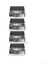
Pull the antenna cables from the system board. 9. 7. Lift up and remove the LVDS support bracket. 8. Disconnect the LVDS cable from the opening on the system board. 10. Remove the display assembly from the computer. 35
Pull the antenna cables from the system board. 9. 7. Lift up and remove the LVDS support bracket. 8. Disconnect the LVDS cable from the opening on the system board. 10. Remove the display assembly from the computer. 35
Owner's Manual
Page 36
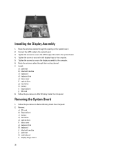
Tighten the screws to secure the LVDS support bracket to the system board. 3. Follow the procedures in After Working Inside Your Computer. Install: a) palmrest b) bluetooth module c) keyboard d) keyboard trim e) base cover f) optical drive g) ...
Tighten the screws to secure the LVDS support bracket to the system board. 3. Follow the procedures in After Working Inside Your Computer. Install: a) palmrest b) bluetooth module c) keyboard d) keyboard trim e) base cover f) optical drive g) ...
Owner's Manual
Page 47
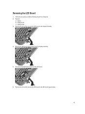
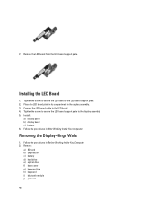
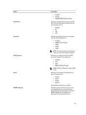
Removing the LED Board 1. Remove: a) battery b) display bezel c) display panel 3. Disconnect the LED-board cable from the display assembly. 5. Remove the screw that secures the LED board to the LED-board support plate. 47 Follow the procedures in Before Working Inside Your Computer. 2. Remove the screw that secures the LED board to the display assembly. 4. Remove the LED-board support plate from the LED board. 6.
Removing the LED Board 1. Remove: a) battery b) display bezel c) display panel 3. Disconnect the LED-board cable from the display assembly. 5. Remove the screw that secures the LED board to the LED-board support plate. 47 Follow the procedures in Before Working Inside Your Computer. 2. Remove the screw that secures the LED board to the display assembly. 4. Remove the LED-board support plate from the LED board. 6.
Owner's Manual
Page 48
... to the LED board. 4. Follow the procedures in the display assembly. 3. Tighten the screw to secure the LED board to the LED board support plate. 2. Install: a) display panel b) display bezel c) battery 6. Place the LED board plate in its compartment in After Working Inside Your Computer. Installing the LED Board 1. 7. ...
... to the LED board. 4. Follow the procedures in the display assembly. 3. Tighten the screw to secure the LED board to the LED board support plate. 2. Install: a) display panel b) display bezel c) battery 6. Place the LED board plate in its compartment in After Working Inside Your Computer. Installing the LED Board 1. 7. ...
Owner's Manual
Page 59
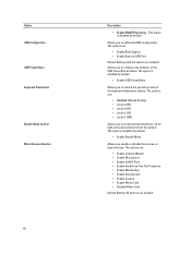
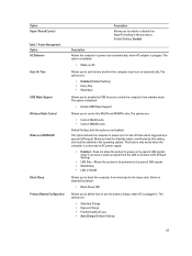
...-drive controller. Option Parallel Port Serial Port SATA Operation Drives SMART Reporting Description • Disabled • Enabled • Enabled w/PXE (Default Setting) Allows you to support RAID mode. Allows you to : • Disabled • COM1 (Default Setting) • COM2 • COM3 • COM4 NOTE: The operating system may allocate resources even...
...-drive controller. Option Parallel Port Serial Port SATA Operation Drives SMART Reporting Description • Disabled • Enabled • Enabled w/PXE (Default Setting) Allows you to support RAID mode. Allows you to : • Disabled • COM1 (Default Setting) • COM2 • COM3 • COM4 NOTE: The operating system may allocate resources even...
Owner's Manual
Page 60
... the operating mode of the USB PowerShare feature. Allows you to configure the behavior of the keyboard illumination feature. The options are: • Enable Boot Support • Enable External USB Port Default Setting: both the options are enabled The option is 100% Allows you to set the mode that will turn...
... the operating mode of the USB PowerShare feature. Allows you to configure the behavior of the keyboard illumination feature. The options are: • Enable Boot Support • Enable External USB Port Default Setting: both the options are enabled The option is 100% Allows you to set the mode that will turn...

Owner's Manual
Page 61
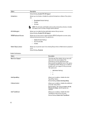
...-SX) Configuration Admin Password System Password Internal HDD-0 Password Strong Password Password Configuration Password Bypass Password Change Non-Admin Setup Changes TPM Security CPU XD Support Description This option is not selected. Default Setting: Enable Strong Password is disabled by default. You can define the length of the processor. 61 The...
...-SX) Configuration Admin Password System Password Internal HDD-0 Password Strong Password Password Configuration Password Bypass Password Change Non-Admin Setup Changes TPM Security CPU XD Support Description This option is not selected. Default Setting: Enable Strong Password is disabled by default. You can define the length of the processor. 61 The...
Owner's Manual
Page 62
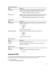
... from entering Setup when an Administrator password is enabled by default. Performance Option Multi Core Support Intel SpeedStep C States Control Intel TurboBoost Description Default Setting: Enable CPU XD Support Allows you to enable or disable multi-core support for the processor. The options are : • Enable (Default Setting) • One Time... options will permanently activate or disable the feature and no further changes will improve with the additional cores. Option Computrace CPU XD Support OROM Keyboard Access Admin Setup Lockout Table 6. Default Setting: Enable CPU XD...
... from entering Setup when an Administrator password is enabled by default. Performance Option Multi Core Support Intel SpeedStep C States Control Intel TurboBoost Description Default Setting: Enable CPU XD Support Allows you to enable or disable multi-core support for the processor. The options are : • Enable (Default Setting) • One Time... options will permanently activate or disable the feature and no further changes will improve with the additional cores. Option Computrace CPU XD Support OROM Keyboard Access Admin Setup Lockout Table 6. Default Setting: Enable CPU XD...
Owner's Manual
Page 63
...special LAN signals when it receives a wake-up signal from standby mode. The options are disabled. The option is disabled • Enable USB Wake Support Allows you to block the computer from the off state when triggered by this setting and must turn on AC Allows you to power up...processor. The option is disabled. • Wake on automatically. Option Hyper-Thread Control Table 7. Power Management Option AC Behavior Auto On Time USB Wake Support Wireless Radio Control Wake on by special LAN signals. • WLAN Only • LAN or WLAN Allows you to enable the USB devices to AC...
...special LAN signals when it receives a wake-up signal from standby mode. The options are disabled. The option is disabled • Enable USB Wake Support Allows you to block the computer from the off state when triggered by this setting and must turn on AC Allows you to power up...processor. The option is disabled. • Wake on automatically. Option Hyper-Thread Control Table 7. Power Management Option AC Behavior Auto On Time USB Wake Support Wireless Radio Control Wake on by special LAN signals. • WLAN Only • LAN or WLAN Allows you to enable the USB devices to AC...
Owner's Manual
Page 65
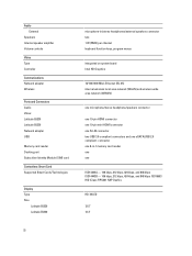
...Wireless Option Wireless Switch Wireless Device Enable Table 11. This option is available. Restart the computer. 2. Go to enable or disable the wireless devices. Virtualization Support Option Virtualization VT for Direct I /O Description This option specifies whether a Virtual Machine Monitor (VMM) can be controlled by default. Allows you to determine ... Monitor (VMM) from utilizing the additional hardware capabilities provided by Intel Virtualization technology. • Enable Intel Virtualization Technology - Table 10. Allows you to support.dell.com/support/downloads. 65
...Wireless Option Wireless Switch Wireless Device Enable Table 11. This option is available. Restart the computer. 2. Go to enable or disable the wireless devices. Virtualization Support Option Virtualization VT for Direct I /O Description This option specifies whether a Virtual Machine Monitor (VMM) can be controlled by default. Allows you to determine ... Monitor (VMM) from utilizing the additional hardware capabilities provided by Intel Virtualization technology. • Enable Intel Virtualization Technology - Table 10. Allows you to support.dell.com/support/downloads. 65

Owner's Manual
Page 69
...to provide extra information about the failed device(s) • View status messages that inform you wish to run the ePSA diagnostics before contacting Dell for specific devices require user interaction. If you of your hardware. Select the device from the left pane and click Run Tests. 6....diagnostics to help you are displayed. If there are any issues, error codes are unable to fix the problem yourself, service and support personnel can use the diagnostics results to test only your computer's hardware without requiring additional equipment or risking data loss. Device Status ...
...to provide extra information about the failed device(s) • View status messages that inform you wish to run the ePSA diagnostics before contacting Dell for specific devices require user interaction. If you of your hardware. Select the device from the left pane and click Run Tests. 6....diagnostics to help you are displayed. If there are any issues, error codes are unable to fix the problem yourself, service and support personnel can use the diagnostics results to test only your computer's hardware without requiring additional equipment or risking data loss. Device Status ...

Owner's Manual
Page 71
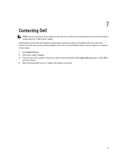
... your computer. The following specifications are only those required by region. For more information regarding the configuration of your computer, click Start → Help and Support and select the option to ship with your computer. System Information Chipset DRAM bus width Flash EPROM PCIe Gen1 bus External Bus Frequency Mobile Intel...
... your computer. The following specifications are only those required by region. For more information regarding the configuration of your computer, click Start → Help and Support and select the option to ship with your computer. System Information Chipset DRAM bus width Flash EPROM PCIe Gen1 bus External Bus Frequency Mobile Intel...
Owner's Manual
Page 72
... controls Video Type Controller Communications Network adapter Wireless Ports and Connectors Audio Video: Latitude E6230 Latitude E6330 Network adapter USB Memory card reader Docking port Subscriber Identity Module (SIM) card Contactless Smart Card Supported Smart Cards/Technologies Display Type Size Latitude E6230 Latitude E6330 microphone-in -1 memory card reader one one eSATA/USB 2.0 compliant- connector one 8-in...
... controls Video Type Controller Communications Network adapter Wireless Ports and Connectors Audio Video: Latitude E6230 Latitude E6330 Network adapter USB Memory card reader Docking port Subscriber Identity Module (SIM) card Contactless Smart Card Supported Smart Cards/Technologies Display Type Size Latitude E6230 Latitude E6330 microphone-in -1 memory card reader one one eSATA/USB 2.0 compliant- connector one 8-in...
Owner's Manual
Page 77
... on your country code at the bottom of the support.dell.com page, or select All to see more choices. 4. Select your area. 7 Contacting Dell NOTE: If you do not have an active Internet connection, you are not a U.S. Dell provides several online and telephone-based support and service options. Availability varies by country and product...
... on your country code at the bottom of the support.dell.com page, or select All to see more choices. 4. Select your area. 7 Contacting Dell NOTE: If you do not have an active Internet connection, you are not a U.S. Dell provides several online and telephone-based support and service options. Availability varies by country and product...


