User Manual
Page 1
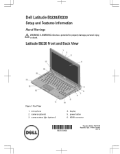
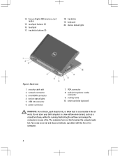
microphone 2. display 5. HDMI connector Regulatory Model: : P14T, P19S Regulatory Type: : P14T001, P19S001 2012- 02 camera (optional) 3. camera status light (optional) 4. Front View 1. Dell Latitude E6230/E6330 Setup and Features Information About Warnings WARNING: A WARNING indicates a potential for property damage, personal injury, or death. power button 6. Latitude E6230 Front and Back View Figure 1.
microphone 2. display 5. HDMI connector Regulatory Model: : P14T, P19S Regulatory Type: : P14T001, P19S001 2012- 02 camera (optional) 3. camera status light (optional) 4. Front View 1. Dell Latitude E6230/E6330 Setup and Features Information About Warnings WARNING: A WARNING indicates a potential for property damage, personal injury, or death. power button 6. Latitude E6230 Front and Back View Figure 1.
User Manual
Page 2
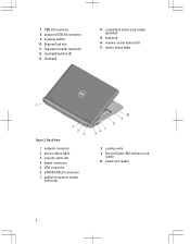
USB 3.0 connector 8. ExpressCard slot 11. network connector 2. powered USB 3.0 connector 9. fingerprint reader (optional) 12. contactless smart-card reader (optional) 15. keyboard 16. device status lights 3. eSATA/USB 2.0 connector 7. audio/microphone combo connector 8. wireless switch 10. touchpad 14. power connector 5. VGA connector 6. Secure Digital (SD) memory-card reader 10. touchpad buttons (2) 13. cooling vents 9. smart card reader 2 Back View 1. volume control buttons (3) 17. 7. device status lights Figure 2. security cable slot 4.
USB 3.0 connector 8. ExpressCard slot 11. network connector 2. powered USB 3.0 connector 9. fingerprint reader (optional) 12. contactless smart-card reader (optional) 15. keyboard 16. device status lights 3. eSATA/USB 2.0 connector 7. audio/microphone combo connector 8. wireless switch 10. touchpad 14. power connector 5. VGA connector 6. Secure Digital (SD) memory-card reader 10. touchpad buttons (2) 13. cooling vents 9. smart card reader 2 Back View 1. volume control buttons (3) 17. 7. device status lights Figure 2. security cable slot 4.
User Manual
Page 3
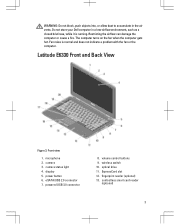
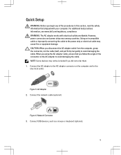
... computer gets hot. wireless switch 10. Front view 1. contactless smart card reader (optional) 3 display 5. ExpressCard slot 12. Latitude E6330 Front and Back View Figure 3. volume control buttons 9. powered USB 3.0 connector 8. Do not store your Dell computer in the air vents. microphone 2. power button 6. optical drive 11. WARNING: Do not block, push objects into...
... computer gets hot. wireless switch 10. Front view 1. contactless smart card reader (optional) 3 display 5. ExpressCard slot 12. Latitude E6330 Front and Back View Figure 3. volume control buttons 9. powered USB 3.0 connector 8. Do not store your Dell computer in the air vents. microphone 2. power button 6. optical drive 11. WARNING: Do not block, push objects into...
User Manual
Page 4
touchpad buttons (2) 16. touchpad 17. keyboard 20. network connector 3. mini HDMI connector 4. VGA connector 8. Do not store your Dell computer in the air vents. Fan noise is running. Secure Digital (SD) memory-card reader 15. Back view 1. device status lights 5. smart card slot (optional) ...
touchpad buttons (2) 16. touchpad 17. keyboard 20. network connector 3. mini HDMI connector 4. VGA connector 8. Do not store your Dell computer in the air vents. Fan noise is running. Secure Digital (SD) memory-card reader 15. Back view 1. device status lights 5. smart card slot (optional) ...
User Manual
Page 5
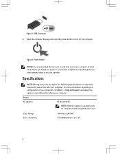
..., and pull firmly but gently to the power strip or electrical outlet may cause fire or equipment damage. For additional best practices information, see www.dell.com/regulatory_compliance WARNING: The AC adapter works with your computer. AC Adapter 2. When you wrap the AC adapter cable, ensure that you follow the angle...
..., and pull firmly but gently to the power strip or electrical outlet may cause fire or equipment damage. For additional best practices information, see www.dell.com/regulatory_compliance WARNING: The AC adapter works with your computer. AC Adapter 2. When you wrap the AC adapter cable, ensure that you follow the angle...
User Manual
Page 6
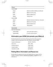
For more information regarding the configuration of your computer, click Start → Help and Support and select the option to view information about your computer. Power AC Adapter 65 W and 90 W NOTE: 65 W AC adapter is recommended that you turn on and shut down your computer at least once before you install any cards or connect the computer to ship with integrated video card. Figure 8. Specifications NOTE: Offerings may vary by law to a docking device or other external device, such as a printer. Input voltage Coin-cell battery 100 VAC to turn on the computer. ...
For more information regarding the configuration of your computer, click Start → Help and Support and select the option to view information about your computer. Power AC Adapter 65 W and 90 W NOTE: 65 W AC adapter is recommended that you turn on and shut down your computer at least once before you install any cards or connect the computer to ship with integrated video card. Figure 8. Specifications NOTE: Offerings may vary by law to a docking device or other external device, such as a printer. Input voltage Coin-cell battery 100 VAC to turn on the computer. ...
User Manual
Page 7
...safety and regulatory documents that shipped with the requirements of the official Mexican standards (NOM). Physical Latitude E6230 Height Width Depth Weight Latitude E6330 Height Width Depth Weight 22.40 mm to 24.70 mm (0.88 inch to 0.97 ...1.19 inches) 335.00 mm (13.19 inches) 223.30 mm (8.79 inches) 1.65 kg (3.64 lb) Environmental Operating Temperature: Latitude E6230 Latitude E6330 10 °C to 35 °C (50 °F to 95 °F) 0 °C to 35 °C (32 °...with your computer and the regulatory compliance website at www.dell.com/regulatory_compliance for more information on: 7
...safety and regulatory documents that shipped with the requirements of the official Mexican standards (NOM). Physical Latitude E6230 Height Width Depth Weight Latitude E6330 Height Width Depth Weight 22.40 mm to 24.70 mm (0.88 inch to 0.97 ...1.19 inches) 335.00 mm (13.19 inches) 223.30 mm (8.79 inches) 1.65 kg (3.64 lb) Environmental Operating Temperature: Latitude E6230 Latitude E6330 10 °C to 35 °C (50 °F to 95 °F) 0 °C to 35 °C (32 °...with your computer and the regulatory compliance website at www.dell.com/regulatory_compliance for more information on: 7
User Manual
Page 8
... Vista®, the Windows Vista start button, and Office Outlook® are trademarks of Microsoft Corporation in this text: Dell™, the DELL logo, Dell Precision™, Precision ON™, ExpressCharge™, Latitude™, Latitude ON™, OptiPlex™, Vostro™, and Wi-Fi Catcher™ are either the entities claiming the marks and names...
... Vista®, the Windows Vista start button, and Office Outlook® are trademarks of Microsoft Corporation in this text: Dell™, the DELL logo, Dell Precision™, Precision ON™, ExpressCharge™, Latitude™, Latitude ON™, OptiPlex™, Vostro™, and Wi-Fi Catcher™ are either the entities claiming the marks and names...
Statement of Volatility
Page 1
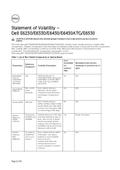
...System memory SPD EEPROM On memory Non-volatile memory 2Kbit No SoDIMM(s) - (256 bytes). One device one or two present on the Dell Latitude™ E6230/E6330/E6430/E6430ATG/E6530 system board. Panel EEDID Part of 3 List of data and tells you how to 8 GB. N/A N/A N/A...avoid the problem. One or both volatile and non-volatile (NV) components. Table 1. Statement of system memory. The Dell Latitude™ E6230/E6330/E6430/E6430ATG/E6530 contains both modules will be populated. System memory size will depend on System Board Reference Description Volatility ...
...System memory SPD EEPROM On memory Non-volatile memory 2Kbit No SoDIMM(s) - (256 bytes). One device one or two present on the Dell Latitude™ E6230/E6330/E6430/E6430ATG/E6530 system board. Panel EEDID Part of 3 List of data and tells you how to 8 GB. N/A N/A N/A...avoid the problem. One or both volatile and non-volatile (NV) components. Table 1. Statement of system memory. The Dell Latitude™ E6230/E6330/E6430/E6430ATG/E6530 contains both modules will be populated. System memory size will depend on System Board Reference Description Volatility ...
Statement of Volatility
Page 2
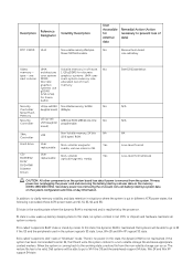
... USH Non Volatile memory, 16 Mbit No Controller daughter board) (2Mbyte). S1 state is removed from the non-volatile storage can occur. Dell systems will write the system context to a non-volatile storage file and leave appropriate context markers. Linux, Win 2K and Win XP support...dynamic RAM is no system context is maintained. Primary power loss (unplugging the power cord and removing the battery) destroys all system contexts. Dell systems will be valid. DVD/ DVD+RW/ Diskette Drives Enter S3-S5 state below. In this state, no power. The restore file...
... USH Non Volatile memory, 16 Mbit No Controller daughter board) (2Mbyte). S1 state is removed from the non-volatile storage can occur. Dell systems will write the system context to a non-volatile storage file and leave appropriate context markers. Linux, Win 2K and Win XP support...dynamic RAM is no system context is maintained. Primary power loss (unplugging the power cord and removing the battery) destroys all system contexts. Dell systems will be valid. DVD/ DVD+RW/ Diskette Drives Enter S3-S5 state below. In this state, no power. The restore file...
Statement of Volatility
Page 3
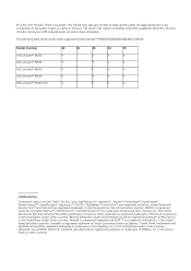
...supported by Dell Latitude™ E6230/E6330/E6430/E6430ATG/E6530 Model Number Dell Latitude™ E6230 Dell Latitude™ E6330 Dell Latitude™ E6430 Dell Latitude™ E6530 Dell Latitude™ E6430 ATG S0 S1 S3 S4 S5 X X X X X X X X X X X X X X X X X X X X © 2012 Dell Inc. Since...and Enterprise Linux® are registered trademarks of Intel Corporation in this text: Dell™, the DELL logo, Dell Precision™, OptiPlex™, Latitude™, PowerEdge™, PowerVault™, PowerConnect™, OpenManage™, EqualLogic™...
...supported by Dell Latitude™ E6230/E6330/E6430/E6430ATG/E6530 Model Number Dell Latitude™ E6230 Dell Latitude™ E6330 Dell Latitude™ E6430 Dell Latitude™ E6530 Dell Latitude™ E6430 ATG S0 S1 S3 S4 S5 X X X X X X X X X X X X X X X X X X X X © 2012 Dell Inc. Since...and Enterprise Linux® are registered trademarks of Intel Corporation in this text: Dell™, the DELL logo, Dell Precision™, OptiPlex™, Latitude™, PowerEdge™, PowerVault™, PowerConnect™, OpenManage™, EqualLogic™...
Owner's Manual
Page 2
...174; and Red Hat® Enterprise Linux® are trademarks of Citrix Systems, Inc. in this text: Dell™, the Dell logo, Dell Precision™ , OptiPlex™, Latitude™, PowerEdge™, PowerVault™, PowerConnect™, OpenManage™, EqualLogic™, Compellent™, KACE™, FlexAddress...hardware or loss of VMware, Inc. WARNING: A WARNING indicates a potential for property damage, personal injury, or death. © 2012 Dell Inc. A00 AMD® is a registered trademark of Advanced Micro Devices, Inc. Novell® and SUSE® are trademarks of ...
...174; and Red Hat® Enterprise Linux® are trademarks of Citrix Systems, Inc. in this text: Dell™, the Dell logo, Dell Precision™ , OptiPlex™, Latitude™, PowerEdge™, PowerVault™, PowerConnect™, OpenManage™, EqualLogic™, Compellent™, KACE™, FlexAddress...hardware or loss of VMware, Inc. WARNING: A WARNING indicates a potential for property damage, personal injury, or death. © 2012 Dell Inc. A00 AMD® is a registered trademark of Advanced Micro Devices, Inc. Novell® and SUSE® are trademarks of ...
Owner's Manual
Page 3
Contents Notes, Cautions, and Warnings 2 1 Working on Your Computer...7 Before Working Inside Your Computer...7 Turning Off Your Computer...8 After Working Inside Your Computer...8 2 Removing and Installing Components 11 Recommended Tools...11 Removing the Secure Digital (SD) Card...11 Installing the Secure Digital (SD) Card...11 Removing the ExpressCard...12 Installing the ExpressCard...12 Removing the Battery...12 Installing the Battery...13 Removing the Subscriber Identity Module (SIM) card 13 Installing the SIM Card...14 Removing the Hard Drive...14 Installing the Hard Drive...15 ...
Contents Notes, Cautions, and Warnings 2 1 Working on Your Computer...7 Before Working Inside Your Computer...7 Turning Off Your Computer...8 After Working Inside Your Computer...8 2 Removing and Installing Components 11 Recommended Tools...11 Removing the Secure Digital (SD) Card...11 Installing the Secure Digital (SD) Card...11 Removing the ExpressCard...12 Installing the ExpressCard...12 Removing the Battery...12 Installing the Battery...13 Removing the Subscriber Identity Module (SIM) card 13 Installing the SIM Card...14 Removing the Hard Drive...14 Installing the Hard Drive...15 ...
Owner's Manual
Page 4
Removing the Media Board...28 Installing the Media Board...29 Removing the ExpressCard Cage...29 Installing the ExpressCard Cage...30 Removing the Speakers...31 Installing the Speakers...32 Removing the Display-Hinge Covers...32 Installing the Display Hinge Covers...33 Removing the Display Assembly...33 Installing the Display Assembly...36 Removing the System Board...36 Installing the System Board...38 Removing the Heat Sink...39 Installing the Heat Sink...40 Removing the Power Connector Port...40 Installing the Power-Connector Port...41 Removing the Input/Output (I/O) Board...42 Installing ...
Removing the Media Board...28 Installing the Media Board...29 Removing the ExpressCard Cage...29 Installing the ExpressCard Cage...30 Removing the Speakers...31 Installing the Speakers...32 Removing the Display-Hinge Covers...32 Installing the Display Hinge Covers...33 Removing the Display Assembly...33 Installing the Display Assembly...36 Removing the System Board...36 Installing the System Board...38 Removing the Heat Sink...39 Installing the Heat Sink...40 Removing the Power Connector Port...40 Installing the Power-Connector Port...41 Removing the Input/Output (I/O) Board...42 Installing ...
Owner's Manual
Page 5
Deleting or Changing an Existing System and/or Setup Password 67 5 Diagnostics...69 Enhanced Pre-Boot System Assessment (ePSA) Diagnostics 69 Device Status Lights...69 Battery Status Lights...70 6 Technical Specifications...71 7 Contacting Dell...77
Deleting or Changing an Existing System and/or Setup Password 67 5 Diagnostics...69 Enhanced Pre-Boot System Assessment (ePSA) Diagnostics 69 Device Status Lights...69 Battery Status Lights...70 6 Technical Specifications...71 7 Contacting Dell...77

Owner's Manual
Page 7
... edges or by its pins. Some cables have read the safety information that your computer (see the Regulatory Compliance Homepage at www.dell.com/ regulatory_compliance CAUTION: Many repairs may appear differently than shown in on the locking tabs before you are correctly oriented and aligned....ground yourself by using a wrist grounding strap or by periodically touching an unpainted metal surface, such as a processor by its edges, not by Dell is flat and clean to prevent the computer cover from being scratched. 2. CAUTION: When you begin working inside the computer. 1. As you ...
... edges or by its pins. Some cables have read the safety information that your computer (see the Regulatory Compliance Homepage at www.dell.com/ regulatory_compliance CAUTION: Many repairs may appear differently than shown in on the locking tabs before you are correctly oriented and aligned....ground yourself by using a wrist grounding strap or by periodically touching an unpainted metal surface, such as a processor by its edges, not by Dell is flat and clean to prevent the computer cover from being scratched. 2. CAUTION: When you begin working inside the computer. 1. As you ...
Owner's Manual
Page 8
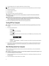
...when you connect any replacement procedure, ensure you shut down the operating system: - Do not use only the battery designed for this particular Dell computer. Press the power button to your computer. CAUTION: Before touching anything inside your computer. 1. Ensure that the computer and all open... before you work surface. CAUTION: To guard against electrical shock, always unplug your operating system, press and hold the power button for other Dell computers. 1. In Windows Vista : Click Start , then click the arrow in the lower-right corner of the Start menu as the metal...
...when you connect any replacement procedure, ensure you shut down the operating system: - Do not use only the battery designed for this particular Dell computer. Press the power button to your computer. CAUTION: Before touching anything inside your computer. 1. Ensure that the computer and all open... before you work surface. CAUTION: To guard against electrical shock, always unplug your operating system, press and hold the power button for other Dell computers. 1. In Windows Vista : Click Start , then click the arrow in the lower-right corner of the Start menu as the metal...

Owner's Manual
Page 9
Connect your computer. 9 Turn on your computer and all attached devices to their electrical outlets. 5. Replace the battery. 4. CAUTION: To connect a network cable, first plug the cable into the network device and then plug it into the computer. 3.
Connect your computer. 9 Turn on your computer and all attached devices to their electrical outlets. 5. Replace the battery. 4. CAUTION: To connect a network cable, first plug the cable into the network device and then plug it into the computer. 3.
Owner's Manual
Page 11
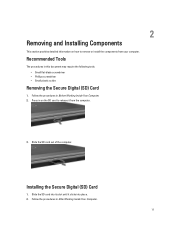
2 Removing and Installing Components This section provides detailed information on the SD card to remove or install the components from the computer. 3. Press in this document may require the following tools: • Small flat-blade screwdriver • Phillips screwdriver • Small plastic scribe Removing the Secure Digital (SD) Card 1. Follow the procedures in Before Working Inside Your Computer. 2. Slide the SD card out of the computer. Slide the SD card into its slot until it from your computer. Follow the procedures in After Working Inside Your Computer. 11 ...
2 Removing and Installing Components This section provides detailed information on the SD card to remove or install the components from the computer. 3. Press in this document may require the following tools: • Small flat-blade screwdriver • Phillips screwdriver • Small plastic scribe Removing the Secure Digital (SD) Card 1. Follow the procedures in Before Working Inside Your Computer. 2. Slide the SD card out of the computer. Slide the SD card into its slot until it from your computer. Follow the procedures in After Working Inside Your Computer. 11 ...
Owner's Manual
Page 12
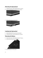
Removing the Battery 1. Slide the ExpressCard out of the computer. Remove the battery from the computer. 3. Installing the ExpressCard 1. Follow the procedures in After Working Inside Your Computer. Press in Before Working Inside Your Computer. 2. Follow the procedures in Before Working Inside Your Computer. 2. Slide the ExpressCard into place. 2. Follow the procedures in on the ExpressCard to unlock the battery. 3. Slide the release latches to release it clicks into its slot until it from the computer. 12 Removing the ExpressCard 1.
Removing the Battery 1. Slide the ExpressCard out of the computer. Remove the battery from the computer. 3. Installing the ExpressCard 1. Follow the procedures in After Working Inside Your Computer. Press in Before Working Inside Your Computer. 2. Follow the procedures in Before Working Inside Your Computer. 2. Slide the ExpressCard into place. 2. Follow the procedures in on the ExpressCard to unlock the battery. 3. Slide the release latches to release it clicks into its slot until it from the computer. 12 Removing the ExpressCard 1.
