User Manual
Page 2
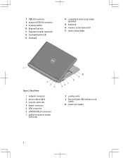
ExpressCard slot 11. keyboard 16. VGA connector 6. touchpad 14. smart card reader 2 wireless switch 10. fingerprint reader (optional) 12. 7. touchpad buttons (2) 13. volume control buttons (3) 17. security cable slot 4. powered USB 3.0 connector 9. power connector 5. cooling vents 9. contactless smart-card reader (optional) 15. USB 3.0 connector 8. eSATA/USB 2.0 connector 7. audio/microphone combo connector 8. device status lights 3. device status lights Figure 2. network connector 2. Secure Digital (SD) memory-card reader 10. Back View 1.
ExpressCard slot 11. keyboard 16. VGA connector 6. touchpad 14. smart card reader 2 wireless switch 10. fingerprint reader (optional) 12. 7. touchpad buttons (2) 13. volume control buttons (3) 17. security cable slot 4. powered USB 3.0 connector 9. power connector 5. cooling vents 9. contactless smart-card reader (optional) 15. USB 3.0 connector 8. eSATA/USB 2.0 connector 7. audio/microphone combo connector 8. device status lights 3. device status lights Figure 2. network connector 2. Secure Digital (SD) memory-card reader 10. Back View 1.
User Manual
Page 4
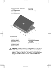
... 17. device status lights 5. audio/microphone combo connector 9. mini HDMI connector 4. Restricting the airflow can damage the computer or cause a fire. Do not store your Dell computer in the air vents. smart card slot (optional) WARNING: Do not block, push objects into, or allow dust to accumulate in a low-airflow environment... the fan or the computer. 4 The computer turns on the fan when the computer gets hot. 14. trackstick buttons (3) 18. cooling vents 10. Back view 1. keyboard 20. device status lights Figure 4.
... 17. device status lights 5. audio/microphone combo connector 9. mini HDMI connector 4. Restricting the airflow can damage the computer or cause a fire. Do not store your Dell computer in the air vents. smart card slot (optional) WARNING: Do not block, push objects into, or allow dust to accumulate in a low-airflow environment... the fan or the computer. 4 The computer turns on the fan when the computer gets hot. 14. trackstick buttons (3) 18. cooling vents 10. Back view 1. keyboard 20. device status lights Figure 4.
User Manual
Page 5
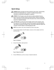
...(optional). NOTE: Some devices may cause fire or equipment damage. AC Adapter 2. Figure 5. Connect USB devices, such as a mouse or keyboard (optional). 5 Using an incompatible cable or improperly connecting the cable to the power strip or electrical outlet may not be included if you ... not the cable itself, and pull firmly but gently to avoid damaging the cable. Figure 6. For additional best practices information, see www.dell.com/regulatory_compliance WARNING: The AC adapter works with your computer. Network Connector 3. CAUTION: When you did not order them. 1. When you ...
...(optional). NOTE: Some devices may cause fire or equipment damage. AC Adapter 2. Figure 5. Connect USB devices, such as a mouse or keyboard (optional). 5 Using an incompatible cable or improperly connecting the cable to the power strip or electrical outlet may not be included if you ... not the cable itself, and pull firmly but gently to avoid damaging the cable. Figure 6. For additional best practices information, see www.dell.com/regulatory_compliance WARNING: The AC adapter works with your computer. Network Connector 3. CAUTION: When you did not order them. 1. When you ...
Owner's Manual
Page 3
... Optical Drive...16 Installing the Optical Drive...17 Removing the Base Cover...18 Installing the Base Cover...18 Removing the Keyboard Trim...18 Installing the Keyboard Trim...19 Removing the Keyboard...19 Installing the Keyboard...21 Removing the Wireless Local Area Network (WLAN) Card 22 Installing the WLAN Card...22 Removing the Bluetooth Module...
... Optical Drive...16 Installing the Optical Drive...17 Removing the Base Cover...18 Installing the Base Cover...18 Removing the Keyboard Trim...18 Installing the Keyboard Trim...19 Removing the Keyboard...19 Installing the Keyboard...21 Removing the Wireless Local Area Network (WLAN) Card 22 Installing the WLAN Card...22 Removing the Bluetooth Module...

Owner's Manual
Page 18
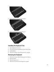
... latch. 6. Install the battery. 4. Remove the screws that secure the base cover to release it from the computer. 18 Using a plastic scribe, pry under the keyboard trim to the computer. 4. Slide the optical drive into its slot. 7. Follow the procedures in After Working Inside Your Computer. Tighten the screws to secure... in the eject handle to the computer. 3. Tighten the screw to secure the optical-drive latch to the optical drive. 4. Install the battery. 9. 3. Removing the Keyboard Trim 1.
... latch. 6. Install the battery. 4. Remove the screws that secure the base cover to release it from the computer. 18 Using a plastic scribe, pry under the keyboard trim to the computer. 4. Slide the optical drive into its slot. 7. Follow the procedures in After Working Inside Your Computer. Tighten the screws to secure... in the eject handle to the computer. 3. Tighten the screw to secure the optical-drive latch to the optical drive. 4. Install the battery. 9. 3. Removing the Keyboard Trim 1.
Owner's Manual
Page 19
4. Align the keyboard trim to remove the keyboard trim from the unit. Press along the sides and bottom. 5. Remove the battery. 3. Pry the keyboard trim along the sides of the keyboard trim until it clicks in place. 3. Install the battery. 4. Lift up to its slot. 2. Remove the keyboard trim. 4. Installing the Keyboard Trim 1. Removing the Keyboard 1. Remove the screws that secure the keyboard to computer. 19 Follow the procedures in Before Working Inside Your Computer. 2. Follow the procedures in After Working Inside Your Computer.
4. Align the keyboard trim to remove the keyboard trim from the unit. Press along the sides and bottom. 5. Remove the battery. 3. Pry the keyboard trim along the sides of the keyboard trim until it clicks in place. 3. Install the battery. 4. Lift up to its slot. 2. Remove the keyboard trim. 4. Installing the Keyboard Trim 1. Removing the Keyboard 1. Remove the screws that secure the keyboard to computer. 19 Follow the procedures in Before Working Inside Your Computer. 2. Follow the procedures in After Working Inside Your Computer.
Owner's Manual
Page 20
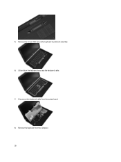
Remove the screws that secure the keyboard to access the keyboard cable. 7. Remove the keyboard from the system board. 8. Disconnect the keyboard cable from the computer. 20 Lift and turn the keyboard to palmrest assembly. 6. 5.
Remove the screws that secure the keyboard to access the keyboard cable. 7. Remove the keyboard from the system board. 8. Disconnect the keyboard cable from the computer. 20 Lift and turn the keyboard to palmrest assembly. 6. 5.

Owner's Manual
Page 21
... place. 4. Tighten the screws to the keyboard using the tape. 2. Flip the computer and tighten the screws to the system board. 3. Install the keyboard trim. 7. Follow the procedures in After Working Inside Your Computer. 21 Connect the keyboard cable to secure the keyboard. 6. Disconnect the keyboard cable from the keyboard. Remove the keyboard cable from the keyboard. 10. 9.
... place. 4. Tighten the screws to the keyboard using the tape. 2. Flip the computer and tighten the screws to the system board. 3. Install the keyboard trim. 7. Follow the procedures in After Working Inside Your Computer. 21 Connect the keyboard cable to secure the keyboard. 6. Disconnect the keyboard cable from the keyboard. Remove the keyboard cable from the keyboard. 10. 9.

Owner's Manual
Page 26
e) optical drive f) base cover g) keyboard trim h) keyboard i) bluetooth module 3. Remove the screws that secure the palmrest assembly to the front of the computer. 4. Disconnect the touchpad cable from the system board. 6. Remove the screws that secure the palmrest assembly to the base of the computer. 5. Disconnect the LED-board cable from the system board. 26
e) optical drive f) base cover g) keyboard trim h) keyboard i) bluetooth module 3. Remove the screws that secure the palmrest assembly to the front of the computer. 4. Disconnect the touchpad cable from the system board. 6. Remove the screws that secure the palmrest assembly to the base of the computer. 5. Disconnect the LED-board cable from the system board. 26
Owner's Manual
Page 27
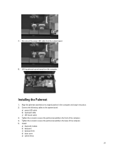
... to secure the palmrest assembly to the base of the computer. 4. Disconnect the power LED cable from the computer. Installing the Palmrest 1. Install: a) bluetooth module b) keyboard c) keyboard trim d) base cover e) optical drive 27 Connect the following cables to its original position in the computer and snap it into place. 2. Align the palmrest...
... to secure the palmrest assembly to the base of the computer. 4. Disconnect the power LED cable from the computer. Installing the Palmrest 1. Install: a) bluetooth module b) keyboard c) keyboard trim d) base cover e) optical drive 27 Connect the following cables to its original position in the computer and snap it into place. 2. Align the palmrest...

Owner's Manual
Page 28
Follow the procedures in Before Working Inside Your Computer. 2. Disconnect the media-board cable from the computer. 28 Removing the Media Board 1. Remove: a) SD card b) ExpressCard c) battery d) hard drive e) optical drive f) base cover g) keyboard trim h) keyboard i) bluetooth module j) palmrest 3. Remove the screws that secure the media board to the computer. 5. Remove the media board from the system board. 4. Follow the procedures in After Working Inside Your Computer. f) hard drive g) battery h) ExpressCard i) SD card 6.
Follow the procedures in Before Working Inside Your Computer. 2. Disconnect the media-board cable from the computer. 28 Removing the Media Board 1. Remove: a) SD card b) ExpressCard c) battery d) hard drive e) optical drive f) base cover g) keyboard trim h) keyboard i) bluetooth module j) palmrest 3. Remove the screws that secure the media board to the computer. 5. Remove the media board from the system board. 4. Follow the procedures in After Working Inside Your Computer. f) hard drive g) battery h) ExpressCard i) SD card 6.

Owner's Manual
Page 29
... Removing the ExpressCard Cage 1. Remove: a) SD card b) ExpressCard c) battery d) hard drive e) optical drive f) base cover g) keyboard trim h) keyboard i) bluetooth module j) palmrest 3. Place the media board in Before Working Inside Your Computer. 2. Follow the procedures in After Working Inside... Your Computer. Install: a) palmrest b) bluetooth module c) keyboard d) keyboard trim e) base cover f) optical drive g) hard drive h) battery i) ExpressCard j) SD card 5. Tighten the screws to the system ...
... Removing the ExpressCard Cage 1. Remove: a) SD card b) ExpressCard c) battery d) hard drive e) optical drive f) base cover g) keyboard trim h) keyboard i) bluetooth module j) palmrest 3. Place the media board in Before Working Inside Your Computer. 2. Follow the procedures in After Working Inside... Your Computer. Install: a) palmrest b) bluetooth module c) keyboard d) keyboard trim e) base cover f) optical drive g) hard drive h) battery i) ExpressCard j) SD card 5. Tighten the screws to the system ...

Owner's Manual
Page 30
Remove the screws that secure the ExpressCard cage to the computer. 3. Remove the ExpressCard cage from the computer. Insert the ExpressCard cage into its compartment. 2. Tighten the screws to secure the ExpressCard cage to the computer. 5. Connect the ExpressCard cable to the system board. 4. 4. Installing the ExpressCard Cage 1. Install: a) palmrest b) bluetooth module c) keyboard d) keyboard trim e) base cover f) optical drive g) hard drive h) battery i) ExpressCard 30
Remove the screws that secure the ExpressCard cage to the computer. 3. Remove the ExpressCard cage from the computer. Insert the ExpressCard cage into its compartment. 2. Tighten the screws to secure the ExpressCard cage to the computer. 5. Connect the ExpressCard cable to the system board. 4. 4. Installing the ExpressCard Cage 1. Install: a) palmrest b) bluetooth module c) keyboard d) keyboard trim e) base cover f) optical drive g) hard drive h) battery i) ExpressCard 30

Owner's Manual
Page 31
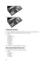
Remove the screws that secure the speakers to the computer. 31 Disconnect the speaker cable from the computer. 5. Removing the Speakers 1. Remove: a) SD card b) ExpressCard c) battery d) hard drive e) optical drive f) base cover g) keyboard trim h) keyboard i) bluetooth module j) palmrest 3. Follow the procedures in Before Working Inside Your Computer. 2. Follow the procedures in After Working Inside Your Computer. j) SD card 5. Release the speaker cable from the system board. 4.
Remove the screws that secure the speakers to the computer. 31 Disconnect the speaker cable from the computer. 5. Removing the Speakers 1. Remove: a) SD card b) ExpressCard c) battery d) hard drive e) optical drive f) base cover g) keyboard trim h) keyboard i) bluetooth module j) palmrest 3. Follow the procedures in Before Working Inside Your Computer. 2. Follow the procedures in After Working Inside Your Computer. j) SD card 5. Release the speaker cable from the system board. 4.
Owner's Manual
Page 32
... the computer. 2. Follow the procedures in Before Working Inside Your Computer. 2. Remove: a) SD card b) ExpressCard c) battery d) hard drive e) optical drive 32 Install: a) palmrest b) bluetooth module c) keyboard d) keyboard trim e) base cover f) optical drive g) hard drive h) battery i) ExpressCard j) SD card 4. Follow the procedures in After Working Inside Your Computer. 6. Installing the Speakers 1. Remove the...
... the computer. 2. Follow the procedures in Before Working Inside Your Computer. 2. Remove: a) SD card b) ExpressCard c) battery d) hard drive e) optical drive 32 Install: a) palmrest b) bluetooth module c) keyboard d) keyboard trim e) base cover f) optical drive g) hard drive h) battery i) ExpressCard j) SD card 4. Follow the procedures in After Working Inside Your Computer. 6. Installing the Speakers 1. Remove the...

Owner's Manual
Page 33
f) base cover g) keyboard trim h) keyboard i) bluetooth module j) palmrest 3. Follow the procedures in After Working Inside Your Computer. Removing the Display Assembly 1. Installing the Display Hinge Covers 1. Remove: 33 Follow the ... to secure the display hinge covers to the computer. 4. Remove the screws that secure the display-hinge covers to the computer. 2. Install: a) palmrest b) bluetooth module c) keyboard d) keyboard trim e) base cover f) optical drive g) hard drive h) battery i) ExpressCard j) SD card 3. Remove the display-hinge covers from the computer.
f) base cover g) keyboard trim h) keyboard i) bluetooth module j) palmrest 3. Follow the procedures in After Working Inside Your Computer. Removing the Display Assembly 1. Installing the Display Hinge Covers 1. Remove: 33 Follow the ... to secure the display hinge covers to the computer. 4. Remove the screws that secure the display-hinge covers to the computer. 2. Install: a) palmrest b) bluetooth module c) keyboard d) keyboard trim e) base cover f) optical drive g) hard drive h) battery i) ExpressCard j) SD card 3. Remove the display-hinge covers from the computer.

Owner's Manual
Page 34
Remove the screws that secure the display assembly to the computer. 6. Remove the screws that secures the left display hinge to the computer. 5. a) SD card b) ExpressCard c) battery d) hard drive e) optical drive f) base cover g) keyboard trim h) keyboard i) bluetooth module j) palmrest 3. Remove the screw that secure the Low-Voltage Differential Signaling (LVDS) support bracket. 34 Release the antenna cables from their routing on the computer. 4.
Remove the screws that secure the display assembly to the computer. 6. Remove the screws that secures the left display hinge to the computer. 5. a) SD card b) ExpressCard c) battery d) hard drive e) optical drive f) base cover g) keyboard trim h) keyboard i) bluetooth module j) palmrest 3. Remove the screw that secure the Low-Voltage Differential Signaling (LVDS) support bracket. 34 Release the antenna cables from their routing on the computer. 4.
Owner's Manual
Page 36
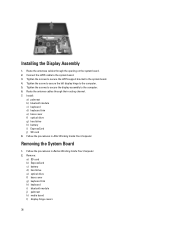
... assembly to the system board. 3. Remove: a) SD card b) ExpressCard c) battery d) hard drive e) optical drive f) base cover g) keyboard trim h) keyboard i) bluetooth module j) palmrest k) media board l) display-hinge covers 36 Connect the LVDS cable to the computer. 6. Follow the procedures in... Your Computer. 2. Tighten the screw to secure the left display hinge to the system board. 4. Install: a) palmrest b) bluetooth module c) keyboard d) keyboard trim e) base cover f) optical drive g) hard drive h) battery i) ExpressCard j) SD card 8. Tighten the screws to secure the LVDS support...
... assembly to the system board. 3. Remove: a) SD card b) ExpressCard c) battery d) hard drive e) optical drive f) base cover g) keyboard trim h) keyboard i) bluetooth module j) palmrest k) media board l) display-hinge covers 36 Connect the LVDS cable to the computer. 6. Follow the procedures in... Your Computer. 2. Tighten the screw to secure the left display hinge to the system board. 4. Install: a) palmrest b) bluetooth module c) keyboard d) keyboard trim e) base cover f) optical drive g) hard drive h) battery i) ExpressCard j) SD card 8. Tighten the screws to secure the LVDS support...
Owner's Manual
Page 38
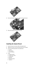
Connect the following cables to the system board. 2. Connect the power connector cable to the system board: a) speaker b) ExpressCard c) coin-cell battery 4. Tighten the screws to secure the system board to the computer. 3. Remove the system board from the system board. 9. Disconnect the power-connector cable from the computer. Installing the System Board 1. Install : a) display assembly b) display hinge covers c) media board d) palmrest e) bluetooth module f) keyboard 38 8.
Connect the following cables to the system board. 2. Connect the power connector cable to the system board: a) speaker b) ExpressCard c) coin-cell battery 4. Tighten the screws to secure the system board to the computer. 3. Remove the system board from the system board. 9. Disconnect the power-connector cable from the computer. Installing the System Board 1. Install : a) display assembly b) display hinge covers c) media board d) palmrest e) bluetooth module f) keyboard 38 8.

Owner's Manual
Page 39
... Inside Your Computer. Remove the screws that secure the heat sink to the system board. 39 Disconnect the heat sink cable from the system board. 4. g) keyboard trim h) base cover i) optical drive j) hard drive k) battery l) ExpressCard m) SD card 5. Remove: a) SD card b) ExpressCard c) battery d) hard drive e) optical drive f) base cover...
... Inside Your Computer. Remove the screws that secure the heat sink to the system board. 39 Disconnect the heat sink cable from the system board. 4. g) keyboard trim h) base cover i) optical drive j) hard drive k) battery l) ExpressCard m) SD card 5. Remove: a) SD card b) ExpressCard c) battery d) hard drive e) optical drive f) base cover...


