User's Guide
Page 9
... Off Your Computer 107 Before Working Inside Your Computer 107 Hard Drive 108 Returning a Hard Drive to Dell 110 Media Bay 110 Removing the Device Security Screw 110 Removing and Installing Media Bay Devices 111 Hinge Cover 112 Keyboard 113 Memory 115 Subscriber Identity Module (SIM) Card 119 Wireless Cards 119 Wireless...
... Off Your Computer 107 Before Working Inside Your Computer 107 Hard Drive 108 Returning a Hard Drive to Dell 110 Media Bay 110 Removing the Device Security Screw 110 Removing and Installing Media Bay Devices 111 Hinge Cover 112 Keyboard 113 Memory 115 Subscriber Identity Module (SIM) Card 119 Wireless Cards 119 Wireless...

User's Guide
Page 112
... you removed a device security screw in "Before You Begin" on page 107. 2 Turn the computer top-side up the hinge cover on the right side. 112 Adding and Replacing Parts NOTICE: The hinge cover is fragile and can be damaged if extreme force is used. NOTICE: To avoid electrostatic discharge, ground yourself... in the indent to carefully pry up , and then open the display all the way (180 degrees) so that it . NOTICE: To avoid damaging the hinge cover, do not lift the cover on both sides simultaneously. 3 Insert a scribe in the Product Information Guide. Be careful when removing the...
... you removed a device security screw in "Before You Begin" on page 107. 2 Turn the computer top-side up the hinge cover on the right side. 112 Adding and Replacing Parts NOTICE: The hinge cover is fragile and can be damaged if extreme force is used. NOTICE: To avoid electrostatic discharge, ground yourself... in the indent to carefully pry up , and then open the display all the way (180 degrees) so that it . NOTICE: To avoid damaging the hinge cover, do not lift the cover on both sides simultaneously. 3 Insert a scribe in the Product Information Guide. Be careful when removing the...
User's Guide
Page 113
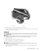
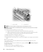
...keycaps on the system board. Be careful when removing and handling the keyboard. 4 Rotate the keyboard forward and lay it . 5 To replace the hinge cover, insert the left to replace. Adding and Replacing Parts 113 To remove the keyboard: 1 Follow the procedures in "Before You Begin" on... page 107. 2 Remove the hinge cover (see "Hinge Cover" on the back of the procedures in this section, follow the safety instructions in the Product Information Guide. Keyboard CAUTION: Before you...
...keycaps on the system board. Be careful when removing and handling the keyboard. 4 Rotate the keyboard forward and lay it . 5 To replace the hinge cover, insert the left to replace. Adding and Replacing Parts 113 To remove the keyboard: 1 Follow the procedures in "Before You Begin" on... page 107. 2 Remove the hinge cover (see "Hinge Cover" on the back of the procedures in this section, follow the safety instructions in the Product Information Guide. Keyboard CAUTION: Before you...

User's Guide
Page 114
... 3 cable connector NOTICE: To avoid scratching the palm rest when replacing the keyboard, hook the tabs along the front edge of the keyboard. 4 Replace the hinge cover. 114 Adding and Replacing Parts To replace the keyboard: 1 Connect the keyboard connector to disconnect the keyboard cable connector from the keyboard connector on...
... 3 cable connector NOTICE: To avoid scratching the palm rest when replacing the keyboard, hook the tabs along the front edge of the keyboard. 4 Replace the hinge cover. 114 Adding and Replacing Parts To replace the keyboard: 1 Connect the keyboard connector to disconnect the keyboard cable connector from the keyboard connector on...
User's Guide
Page 115
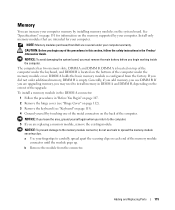
... to the memory module connector, do not use DIMM B. The computer has two memory slots, DIMM A and DIMM B. b Remove the module from Dell are intended for information on the memory supported by installing memory modules on the back of the memory module connector until the module pops up.... If you begin any of the procedures in this section, follow the safety instructions in "Before You Begin" on page 107. 2 Remove the hinge cover (see "Hinge Cover" on page 112). 3 Remove the keyboard (see "Keyboard" on page 113). 4 Ground yourself by touching one of the metal connectors on...
... to the memory module connector, do not use DIMM B. The computer has two memory slots, DIMM A and DIMM B. b Remove the module from Dell are intended for information on the memory supported by installing memory modules on the back of the memory module connector until the module pops up.... If you begin any of the procedures in this section, follow the safety instructions in "Before You Begin" on page 107. 2 Remove the hinge cover (see "Hinge Cover" on page 112). 3 Remove the keyboard (see "Keyboard" on page 113). 4 Ground yourself by touching one of the metal connectors on...
User's Guide
Page 116
... not installed properly, the computer may not boot properly. As the computer boots, it . 7 Replace the keyboard (see "Keyboard" on page 113). 8 Replace the hinge cover (see "Hinge Cover" on page 107. 116 Adding and Replacing Parts 1 2 1 memory module 2 securing clips (2) NOTICE: Insert memory modules at a 45-degree angle, and rotate the...
... not installed properly, the computer may not boot properly. As the computer boots, it . 7 Replace the keyboard (see "Keyboard" on page 113). 8 Replace the hinge cover (see "Hinge Cover" on page 107. 116 Adding and Replacing Parts 1 2 1 memory module 2 securing clips (2) NOTICE: Insert memory modules at a 45-degree angle, and rotate the...

User's Guide
Page 120
... slightly. 120 Adding and Replacing Parts Wireless Local Area Network (WLAN) Cards 1 Follow the procedures in "Before You Begin" on page 107. 2 Remove the hinge cover (see "Hinge Cover" on page 112). 3 Remove the keyboard (see "Keyboard" on page 113). 4 Ground yourself by pushing the metal securing brackets away from the card...
... slightly. 120 Adding and Replacing Parts Wireless Local Area Network (WLAN) Cards 1 Follow the procedures in "Before You Begin" on page 107. 2 Remove the hinge cover (see "Hinge Cover" on page 112). 3 Remove the keyboard (see "Keyboard" on page 113). 4 Ground yourself by pushing the metal securing brackets away from the card...

User's Guide
Page 121
... card to ensure correct insertion. NOTICE: The card connector is keyed to realign it clicks. If you route the cables correctly. 8 Reinstall the keyboard and hinge cover. 1 2 1 WLAN card 2 metal securing brackets (2) c Lift the card out of or under the card. NOTE: For more specific information about which cable to connect...
... card to ensure correct insertion. NOTICE: The card connector is keyed to realign it clicks. If you route the cables correctly. 8 Reinstall the keyboard and hinge cover. 1 2 1 WLAN card 2 metal securing brackets (2) c Lift the card out of or under the card. NOTE: For more specific information about which cable to connect...

User's Guide
Page 122
..., go to step 6. Mobile Broadband or Wireless Wide Area Network (WWAN) Cards 1 Follow the procedures in "Before You Begin" on page 107. 2 Remove the hinge cover (see "Hinge Cover" on page 112). 3 Remove the keyboard (see "Keyboard" on the back of the metal connectors on page 113). 4 Ground yourself by pushing the...
..., go to step 6. Mobile Broadband or Wireless Wide Area Network (WWAN) Cards 1 Follow the procedures in "Before You Begin" on page 107. 2 Remove the hinge cover (see "Hinge Cover" on page 112). 3 Remove the keyboard (see "Keyboard" on the back of the metal connectors on page 113). 4 Ground yourself by pushing the...

User's Guide
Page 123
.... b Connect the antenna cables to the WWAN card, ensuring that correspond to realign it clicks. If you route the cables correctly. 7 Reinstall the keyboard and hinge cover. Adding and Replacing Parts 123 FCM (Flash Cache Module) The FCM, or Flash Cache Module, is an internal flash drive that came with the...
.... b Connect the antenna cables to the WWAN card, ensuring that correspond to realign it clicks. If you route the cables correctly. 7 Reinstall the keyboard and hinge cover. Adding and Replacing Parts 123 FCM (Flash Cache Module) The FCM, or Flash Cache Module, is an internal flash drive that came with the...

User's Guide
Page 124
... Vista® operating system. NOTE: This card is already installed. 1 Follow the procedures in "Before You Begin" on page 107. 2 Remove the hinge cover (see "Hinge Cover" on page 112). 3 Remove the keyboard (see "Keyboard" on page 113). 4 Ground yourself by touching one of the metal connectors on the... back of its connector. When installing this card, do not install it clicks. 8 Reinstall the keyboard and hinge cover. 124 Adding and Replacing Parts NOTE: If you return to your computer, the card is only compatible with the connectors at a 45 ...
... Vista® operating system. NOTE: This card is already installed. 1 Follow the procedures in "Before You Begin" on page 107. 2 Remove the hinge cover (see "Hinge Cover" on page 112). 3 Remove the keyboard (see "Keyboard" on page 113). 4 Ground yourself by touching one of the metal connectors on the... back of its connector. When installing this card, do not install it clicks. 8 Reinstall the keyboard and hinge cover. 124 Adding and Replacing Parts NOTE: If you return to your computer, the card is only compatible with the connectors at a 45 ...

User's Guide
Page 125
... the card from its compartment in your computer, it is already installed. 1 Follow the procedures in "Before You Begin" on page 107. 2 Remove the hinge cover (see "Hinge Cover" on the back panel of the computer. NOTICE: To avoid electrostatic discharge, ground yourself by using a wrist grounding strap or by periodically touching...
... the card from its compartment in your computer, it is already installed. 1 Follow the procedures in "Before You Begin" on page 107. 2 Remove the hinge cover (see "Hinge Cover" on the back panel of the computer. NOTICE: To avoid electrostatic discharge, ground yourself by using a wrist grounding strap or by periodically touching...

User's Guide
Page 126
..." on the back panel of the computer. Coin-Cell Battery CAUTION: Before performing the following procedures, follow the safety instructions in the compartment. 7 Reinstall the hinge cover. NOTICE: To avoid electrostatic discharge, ground yourself by using a wrist grounding strap or by rotating and sliding into the retention tab in your Product...
..." on the back panel of the computer. Coin-Cell Battery CAUTION: Before performing the following procedures, follow the safety instructions in the compartment. 7 Reinstall the hinge cover. NOTICE: To avoid electrostatic discharge, ground yourself by using a wrist grounding strap or by rotating and sliding into the retention tab in your Product...

User's Guide
Page 127
Adding and Replacing Parts 127 1 3 2 1 plastic sleeve 2 coin-cell battery 3 battery cable connector 3 Remove the battery cable connector from the connector on the system board. 4 Being careful not to break the plastic, slightly raise the corner of the plastic sleeve above the battery. 5 While holding the plastic sleeve, grasp the battery and pull it out of the battery compartment. 6 Install the new coin-cell battery into the plastic sleeve. 7 Connect the cable connector to the system board. 8 Reinstall the keyboard and hinge cover.
Adding and Replacing Parts 127 1 3 2 1 plastic sleeve 2 coin-cell battery 3 battery cable connector 3 Remove the battery cable connector from the connector on the system board. 4 Being careful not to break the plastic, slightly raise the corner of the plastic sleeve above the battery. 5 While holding the plastic sleeve, grasp the battery and pull it out of the battery compartment. 6 Install the new coin-cell battery into the plastic sleeve. 7 Connect the cable connector to the system board. 8 Reinstall the keyboard and hinge cover.


