
Service Manual
Page 1
...without the written permission of Intel Corporation; Information in this text: Dell, the DELL logo, and Latitude are trademarks of your computer. Model PP11L November 2005 Rev. Bluetooth is a registered trademark owned by Dell Inc. A01 NOTICE: A NOTICE indicates either the entities claiming the ...to either potential damage to hardware or loss of data and tells you make better use of Dell Inc.; Dell Inc. under license. Dell™ Latitude™ D610 Service Manual Before You Begin System Components Internal Card With Bluetooth® Wireless Technology Hard Drive Center...
...without the written permission of Intel Corporation; Information in this text: Dell, the DELL logo, and Latitude are trademarks of your computer. Model PP11L November 2005 Rev. Bluetooth is a registered trademark owned by Dell Inc. A01 NOTICE: A NOTICE indicates either the entities claiming the ...to either potential damage to hardware or loss of data and tells you make better use of Dell Inc.; Dell Inc. under license. Dell™ Latitude™ D610 Service Manual Before You Begin System Components Internal Card With Bluetooth® Wireless Technology Hard Drive Center...
Service Manual
Page 2
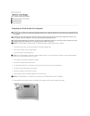
... disconnect any work surface is flat and clean to prevent scratching the computer cover. 2. Back to Contents Page Before You Begin Dell™ Latitude™ D610 Service Manual Preparing to Work Inside the Computer Recommended Tools Computer Orientation Screw Identification Preparing to Work Inside the Computer CAUTION: Only ... slot. 9. Remove any of the computer, and then remove the battery from the bay. Hold a card by its edges or by Dell is off the computer and all other external cables from the computer. 8. If the computer is connected to servicing that the computer is ...
... disconnect any work surface is flat and clean to prevent scratching the computer cover. 2. Back to Contents Page Before You Begin Dell™ Latitude™ D610 Service Manual Preparing to Work Inside the Computer Recommended Tools Computer Orientation Screw Identification Preparing to Work Inside the Computer CAUTION: Only ... slot. 9. Remove any of the computer, and then remove the battery from the bay. Hold a card by its edges or by Dell is off the computer and all other external cables from the computer. 8. If the computer is connected to servicing that the computer is ...
Service Manual
Page 5
The computer continues to Contents Page Flashing the BIOS Dell™ Latitude™ D610 Service Manual 1. When the flash update is plugged in and that appear on the computer. Remove the flash BIOS update program floppy or CD from a ...
The computer continues to Contents Page Flashing the BIOS Dell™ Latitude™ D610 Service Manual 1. When the flash update is plugged in and that appear on the computer. Remove the flash BIOS update program floppy or CD from a ...
Service Manual
Page 6
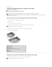
.... Disconnect the card cable connector from the computer. NOTICE: Press down the lever gently to Contents Page Internal Card With Bluetooth® Wireless Technology Dell™ Latitude™ D610 Service Manual Removing the Internal Card With Bluetooth® Wireless Technology Installing the Internal Card With Bluetooth® Wireless Technology CAUTION: Before performing the...
.... Disconnect the card cable connector from the computer. NOTICE: Press down the lever gently to Contents Page Internal Card With Bluetooth® Wireless Technology Dell™ Latitude™ D610 Service Manual Removing the Internal Card With Bluetooth® Wireless Technology Installing the Internal Card With Bluetooth® Wireless Technology CAUTION: Before performing the...
Service Manual
Page 8
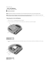
... the coin-cell battery out of the securing sleeve. 1 coin-cell battery 2 battery connector on system board Back to Contents Page Coin-Cell Battery Dell™ Latitude™ D610 Service Manual Removing the Coin-Cell Battery Installing the Coin-Cell Battery CAUTION: Before you touch any of your computer's electronic components. Disconnect the...
... the coin-cell battery out of the securing sleeve. 1 coin-cell battery 2 battery connector on system board Back to Contents Page Coin-Cell Battery Dell™ Latitude™ D610 Service Manual Removing the Coin-Cell Battery Installing the Coin-Cell Battery CAUTION: Before you touch any of your computer's electronic components. Disconnect the...
Service Manual
Page 10
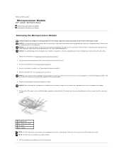
... Mini RSL for the microprocessor, do not touch the heat transfer areas on the microprocessor thermal-cooling assembly. Back to Contents Page Microprocessor Module Dell™ Latitude™ D610 Service Manual Removing the Microprocessor Module Installing the Microprocessor Module Removing the Microprocessor Module CAUTION: Before you cannot turn the screw any of the...
... Mini RSL for the microprocessor, do not touch the heat transfer areas on the microprocessor thermal-cooling assembly. Back to Contents Page Microprocessor Module Dell™ Latitude™ D610 Service Manual Removing the Microprocessor Module Installing the Microprocessor Module Removing the Microprocessor Module CAUTION: Before you cannot turn the screw any of the...
Service Manual
Page 12
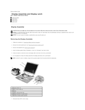
... on the computer. Loosen the captive screw that it lies flat against your work surface. 5. Back to Contents Page Display Assembly and Display Latch Dell™ Latitude™ D610 Service Manual Display Assembly Display Bezel Display Panel Display Latch Display Assembly CAUTION: Before you remove the palm rest. Remove the center control cover...
... on the computer. Loosen the captive screw that it lies flat against your work surface. 5. Back to Contents Page Display Assembly and Display Latch Dell™ Latitude™ D610 Service Manual Display Assembly Display Bezel Display Panel Display Latch Display Assembly CAUTION: Before you remove the palm rest. Remove the center control cover...
Service Manual
Page 18
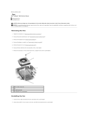
... the center control cover (see "Removing the Display Assembly"). 5. Connect the fan cable connector to Work Inside the Computer." 2. Back to Contents Page Fan Dell™ Latitude™ D610 Service Manual Removing the Fan Installing the Fan CAUTION: Before you begin any of the procedures in this section, follow the safety instructions in...
... the center control cover (see "Removing the Display Assembly"). 5. Connect the fan cable connector to Work Inside the Computer." 2. Back to Contents Page Fan Dell™ Latitude™ D610 Service Manual Removing the Fan Installing the Fan CAUTION: Before you begin any of the procedures in this section, follow the safety instructions in...
Service Manual
Page 20
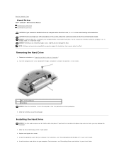
NOTE: Dell does not guarantee compatibility or provide support for hard drives from the computer when the drive is hot, do not touch the metal housing of .... even a slight bump can damage the drive. Removing the Hard Drive 1. If you force the hard drive into place. Back to Contents Page Hard Drive Dell™ Latitude™ D610 Service Manual Removing the Hard Drive Installing the Hard Drive CAUTION: If you remove the hard drive from sources other than...
NOTE: Dell does not guarantee compatibility or provide support for hard drives from the computer when the drive is hot, do not touch the metal housing of .... even a slight bump can damage the drive. Removing the Hard Drive 1. If you force the hard drive into place. Back to Contents Page Hard Drive Dell™ Latitude™ D610 Service Manual Removing the Hard Drive Installing the Hard Drive CAUTION: If you remove the hard drive from sources other than...
Service Manual
Page 22
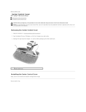
... control cover Installing the Center Control Cover Gently snap the center control cover into place starting from left to Contents Page Center Control Cover Dell™ Latitude™ D610 Service Manual Removing the Center Control Cover Installing the Center Control Cover CAUTION: Before you begin any of the procedures in this section, follow...
... control cover Installing the Center Control Cover Gently snap the center control cover into place starting from left to Contents Page Center Control Cover Dell™ Latitude™ D610 Service Manual Removing the Center Control Cover Installing the Center Control Cover CAUTION: Before you begin any of the procedures in this section, follow...
Service Manual
Page 23
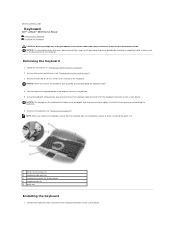
... screws (2) 2 keyboard cable pull-tab 3 keyboard connector on the system board. Be careful when removing and handling the keyboard. 6. Back to Contents Page Keyboard Dell™ Latitude™ D610 Service Manual Removing the Keyboard Installing the Keyboard CAUTION: Before you begin any of the keyboard. Follow the instructions in the Product Information Guide...
... screws (2) 2 keyboard cable pull-tab 3 keyboard connector on the system board. Be careful when removing and handling the keyboard. 6. Back to Contents Page Keyboard Dell™ Latitude™ D610 Service Manual Removing the Keyboard Installing the Keyboard CAUTION: Before you begin any of the keyboard. Follow the instructions in the Product Information Guide...
Service Manual
Page 25
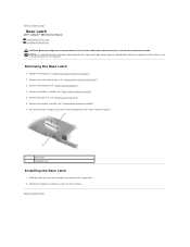
.... Remove the display assembly (see "Removing the Display Assembly"). 5. Slide the latch over the notch located in place. Back to Contents Page Base Latch Dell™ Latitude™ D610 Service Manual Removing the Base Latch Installing the Base Latch CAUTION: Before you begin any of the system base. 2. NOTICE: To avoid electrostatic discharge...
.... Remove the display assembly (see "Removing the Display Assembly"). 5. Slide the latch over the notch located in place. Back to Contents Page Base Latch Dell™ Latitude™ D610 Service Manual Removing the Base Latch Installing the Base Latch CAUTION: Before you begin any of the system base. 2. NOTICE: To avoid electrostatic discharge...
Service Manual
Page 26
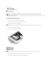
... safety instructions in "Preparing to Work Inside the Computer. 2. Disconnect the antenna cables from the routing clips. 5. Back to Contents Page Mini PCI Card Dell™ Latitude™ D610 Service Manual Removing the Mini PCI Card Installing the Mini PCI Card CAUTION: Before you are replacing a Mini PCI card, remove the existing card...
... safety instructions in "Preparing to Work Inside the Computer. 2. Disconnect the antenna cables from the routing clips. 5. Back to Contents Page Mini PCI Card Dell™ Latitude™ D610 Service Manual Removing the Mini PCI Card Installing the Mini PCI Card CAUTION: Before you are replacing a Mini PCI card, remove the existing card...
Service Manual
Page 29
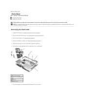
... board. 1 touch pad connector 2 screws (2) at top of the procedures in this section, follow the safety instructions in "Preparing to Contents Page Palm Rest Dell™ Latitude™ D610 Service Manual Removing the Palm Rest Installing the Palm Rest CAUTION: Before you begin any of palm rest 3 palm rest 4 computer base 7. Removing the...
... board. 1 touch pad connector 2 screws (2) at top of the procedures in this section, follow the safety instructions in "Preparing to Contents Page Palm Rest Dell™ Latitude™ D610 Service Manual Removing the Palm Rest Installing the Palm Rest CAUTION: Before you begin any of palm rest 3 palm rest 4 computer base 7. Removing the...
Service Manual
Page 33
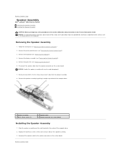
... the speaker cable from the speaker assembly. 8. Remove the two M2.5 x 5-mm screws (one on the speaker assembly. 3. Back to Contents Page Speaker Assembly Dell™ Latitude™ D610 Service Manual Removing the Speaker Assembly Installing the Speaker Assembly CAUTION: Before you begin any of the computer base. 1 speaker assembly 2 M2.5 x 5-mm screws...
... the speaker cable from the speaker assembly. 8. Remove the two M2.5 x 5-mm screws (one on the speaker assembly. 3. Back to Contents Page Speaker Assembly Dell™ Latitude™ D610 Service Manual Removing the Speaker Assembly Installing the Speaker Assembly CAUTION: Before you begin any of the computer base. 1 speaker assembly 2 M2.5 x 5-mm screws...
Service Manual
Page 35
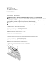
..."). 6. Remove the palm rest (see "Removing the Keyboard"). 4. Remove the speaker assembly (see "Removing the Center Control Cover"). 3. Back to Contents Page System Board Dell™ Latitude™ D610 Service Manual Removing the System Board Installing the System Board Removing the System Board CAUTION: Before you begin any installed batteries. The system board...
..."). 6. Remove the palm rest (see "Removing the Keyboard"). 4. Remove the speaker assembly (see "Removing the Center Control Cover"). 3. Back to Contents Page System Board Dell™ Latitude™ D610 Service Manual Removing the System Board Installing the System Board Removing the System Board CAUTION: Before you begin any installed batteries. The system board...
Service Manual
Page 38
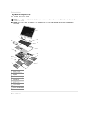
Damage due to servicing that a part can be replaced by performing the removal procedure in this document assumes that is not authorized by Dell is not covered by your computer. NOTICE: Unless otherwise noted, each procedure in reverse order. 1 display assembly 2 center control cover 3 keyboard 4 palm rest 5...primary battery 9 coin-cell battery 10 modem 11 thermal cooling assembly 12 hard drive Back to Contents Page Back to Contents Page System Components Dell™ Latitude™ D610 Service Manual NOTICE: Only a certified service technician should perform repairs on your warranty.
Damage due to servicing that a part can be replaced by performing the removal procedure in this document assumes that is not authorized by Dell is not covered by your computer. NOTICE: Unless otherwise noted, each procedure in reverse order. 1 display assembly 2 center control cover 3 keyboard 4 palm rest 5...primary battery 9 coin-cell battery 10 modem 11 thermal cooling assembly 12 hard drive Back to Contents Page Back to Contents Page System Components Dell™ Latitude™ D610 Service Manual NOTICE: Only a certified service technician should perform repairs on your warranty.
Service Manual
Page 39
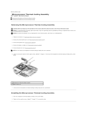
..., and remove any of the procedures in this section, follow the safety instructions in consecutive order. Back to Contents Page Microprocessor Thermal-Cooling Assembly Dell™ Latitude™ D610 Service Manual Removing the Microprocessor Thermal-Cooling Assembly Installing the Microprocessor Thermal-Cooling Assembly Removing the Microprocessor Thermal-Cooling Assembly CAUTION: Before you begin...
..., and remove any of the procedures in this section, follow the safety instructions in consecutive order. Back to Contents Page Microprocessor Thermal-Cooling Assembly Dell™ Latitude™ D610 Service Manual Removing the Microprocessor Thermal-Cooling Assembly Installing the Microprocessor Thermal-Cooling Assembly Removing the Microprocessor Thermal-Cooling Assembly CAUTION: Before you begin...

Service Manual
Page 41
Reproduction in any proprietary interest in this text: Dell, the DELL logo, and Latitude are trademarks of Dell Inc. disclaims any manner whatsoever without notice. © 2004-2005 Dell Inc. A01 Back to Contents Page Information in trademarks and trade names other than its own. All rights reserved. Bluetooth is ...make better use of Intel Corporation; Other trademarks and trade names may be used by Bluetooth SIG, Inc. Back to Contents Page Dell™ Latitude™ D610 Service Manual NOTE: A NOTE indicates important information that helps you how to avoid the problem.
Reproduction in any proprietary interest in this text: Dell, the DELL logo, and Latitude are trademarks of Dell Inc. disclaims any manner whatsoever without notice. © 2004-2005 Dell Inc. A01 Back to Contents Page Information in trademarks and trade names other than its own. All rights reserved. Bluetooth is ...make better use of Intel Corporation; Other trademarks and trade names may be used by Bluetooth SIG, Inc. Back to Contents Page Dell™ Latitude™ D610 Service Manual NOTE: A NOTE indicates important information that helps you how to avoid the problem.

Service Manual
Page 42
...their edges, and do so by touching an unpainted metal surface. Back to Contents Page Memory Module, Modem, and Devices Dell™ Latitude™ D610 Service Manual Memory Module Modem Devices Memory Module CAUTION: Before you are covered under your computer's electronic components. Your computer...the memory module connector, do not use DDR2 memory modules in your fingertips to components inside your computer, discharge static electricity from Dell are replacing a memory module, remove the existing module. 4. Remove the module from the bottom of your computer warranty. CAUTION:...
...their edges, and do so by touching an unpainted metal surface. Back to Contents Page Memory Module, Modem, and Devices Dell™ Latitude™ D610 Service Manual Memory Module Modem Devices Memory Module CAUTION: Before you are covered under your computer's electronic components. Your computer...the memory module connector, do not use DDR2 memory modules in your fingertips to components inside your computer, discharge static electricity from Dell are replacing a memory module, remove the existing module. 4. Remove the module from the bottom of your computer warranty. CAUTION:...


