
Service Manual
Page 4
... Replacing the Hard-Disk Drive Assembly 11 Modular Bay Devices (Diskette Drive, CD-ROM Drive, DVD-ROM Drive, CD-RW Drive, SuperDisk LS-120 Drive, Battery, or Travel Module) . . . . 12 Memory Module Cover 12 Removing the Memory Module Cover 12 Memory Modules 13 Removing the Memory Modules 13 Replacing the Memory...
... Replacing the Hard-Disk Drive Assembly 11 Modular Bay Devices (Diskette Drive, CD-ROM Drive, DVD-ROM Drive, CD-RW Drive, SuperDisk LS-120 Drive, Battery, or Travel Module) . . . . 12 Memory Module Cover 12 Removing the Memory Module Cover 12 Memory Modules 13 Removing the Memory Modules 13 Replacing the Memory...
Service Manual
Page 5
Figure 5. Figure 10. Figure 4. Figure 7. Figure 8. Figure 11. Figure 16. Computer Orientation 1 Main Battery Removal 3 Screw Identification 3 Disconnecting a Cable from an Interface Connector 5 Exploded View-Computer 10 Hard-Disk Drive Assembly Removal 11 Modular Bay...27 Replacing the 12.1-Inch LCD Panel 28 Display Assembly Latch 29 Palmrest Assembly 30 Removing the Palmrest Assembly 30 Reserve Battery 32 Removing the Reserve Battery 32 Modem Assembly 33 Removing the Modem Assembly 33 Replacing the Modem Assembly 33 System Board Assembly 34 Removing the System...
Figure 5. Figure 10. Figure 4. Figure 7. Figure 8. Figure 11. Figure 16. Computer Orientation 1 Main Battery Removal 3 Screw Identification 3 Disconnecting a Cable from an Interface Connector 5 Exploded View-Computer 10 Hard-Disk Drive Assembly Removal 11 Modular Bay...27 Replacing the 12.1-Inch LCD Panel 28 Display Assembly Latch 29 Palmrest Assembly 30 Removing the Palmrest Assembly 30 Reserve Battery 32 Removing the Reserve Battery 32 Modem Assembly 33 Removing the Modem Assembly 33 Replacing the Modem Assembly 33 System Board Assembly 34 Removing the System...

Service Manual
Page 10
... (see Figure 2). M2.5x20 M2.5x10 M3.0x5 M2.5x4 M2.5x4 M3.0x3 M2.0x3 support.dell.com Dell Latitude CPt V/CPt S Series and CPx H/CPx J Series Service Manual 3 Then slide the battery out of the computer. Ground yourself by touching the unpainted metal surface of the I /O panel to check for that might harm components...
... (see Figure 2). M2.5x20 M2.5x10 M3.0x5 M2.5x4 M2.5x4 M3.0x3 M2.0x3 support.dell.com Dell Latitude CPt V/CPt S Series and CPx H/CPx J Series Service Manual 3 Then slide the battery out of the computer. Ground yourself by touching the unpainted metal surface of the I /O panel to check for that might harm components...

Service Manual
Page 13
... and are provided for removing and replacing these parts and assemblies. Table 2 lists the parts and assemblies available for the manufacturer's name. 6 Dell Latitude CPt V/CPt S Series and CPx H/CPx J Series Service Manual Customer kit, AC adapter AC adapter Power cable, U.S. CUS, ADPT, AC, EXT, 20V, 70W, NBK ADPT, AC... 20V, 70W, 3W, BA CORD, PWR, 110V, 6F, AC, 3W/3P, US Customer kit, main battery CUS, BTRY, 14.4V, 8CELL, LITH 2 CUS, BTRY, 9.6V, 8CELL, NiMH (option for CPt S-Series only) Main battery BTRY, 53WHR, 14.4V, 8CELL, LITH BTRY, MAIN, 9.6V, 8, NIMH (option for CPt S-Series ...
... and are provided for removing and replacing these parts and assemblies. Table 2 lists the parts and assemblies available for the manufacturer's name. 6 Dell Latitude CPt V/CPt S Series and CPx H/CPx J Series Service Manual Customer kit, AC adapter AC adapter Power cable, U.S. CUS, ADPT, AC, EXT, 20V, 70W, NBK ADPT, AC... 20V, 70W, 3W, BA CORD, PWR, 110V, 6F, AC, 3W/3P, US Customer kit, main battery CUS, BTRY, 14.4V, 8CELL, LITH 2 CUS, BTRY, 9.6V, 8CELL, NiMH (option for CPt S-Series only) Main battery BTRY, 53WHR, 14.4V, 8CELL, LITH BTRY, MAIN, 9.6V, 8, NIMH (option for CPt S-Series ...

Service Manual
Page 14
Hard-disk drive carrier ASSY, CARR, HD Palmrest assembly ASSY, PLMRST, TPAD 20 Palmrest screws (5) SCR, M2.5X20, PHH, LP, ZPS 19 Reserve battery CUS, BTRY, RESERVE Euro-language specific KYBD, nn, iiii*, D-PTG, EMEA 10 keyboard Asian-language specific keyboard KYBD, nn, iiii*, D-PTG, APCC English (U.K.) KYBD, 88, ... 14.1-inch flex cable ASSY, CBL, FLX, TFT 12.1-inch flex cable ASSY, CBL, FLX, W/EXTN,12.1 14 14 16 16 14 16, 17 support.dell.com Dell Latitude CPt V/CPt S Series and CPx H/CPx J Series Service Manual 7
Hard-disk drive carrier ASSY, CARR, HD Palmrest assembly ASSY, PLMRST, TPAD 20 Palmrest screws (5) SCR, M2.5X20, PHH, LP, ZPS 19 Reserve battery CUS, BTRY, RESERVE Euro-language specific KYBD, nn, iiii*, D-PTG, EMEA 10 keyboard Asian-language specific keyboard KYBD, nn, iiii*, D-PTG, APCC English (U.K.) KYBD, 88, ... 14.1-inch flex cable ASSY, CBL, FLX, TFT 12.1-inch flex cable ASSY, CBL, FLX, W/EXTN,12.1 14 14 16 16 14 16, 17 support.dell.com Dell Latitude CPt V/CPt S Series and CPx H/CPx J Series Service Manual 7

Service Manual
Page 17
display assembly keyboard palmrest assembly hard-disk drive internal modem (may not apply to your system) system board main battery case plug for modem bottom case assembly modular bay device The following subsections provide instructions for removing and replacing field-replaceable parts and assemblies. 10 Dell Latitude CPt V/CPt S Series and CPx H/CPx J Series Service Manual
display assembly keyboard palmrest assembly hard-disk drive internal modem (may not apply to your system) system board main battery case plug for modem bottom case assembly modular bay device The following subsections provide instructions for removing and replacing field-replaceable parts and assemblies. 10 Dell Latitude CPt V/CPt S Series and CPx H/CPx J Series Service Manual

Service Manual
Page 18
... 1. Turn the computer over and replace the 5-mm screw on the left side of the hard-disk drive door (see Figure 6). support.dell.com Dell Latitude CPt V/CPt S Series and CPx H/CPx J Series Service Manual 11 The drive is on the left side of the computer. 2. Slide the drive door down until it aligns with...
... 1. Turn the computer over and replace the 5-mm screw on the left side of the hard-disk drive door (see Figure 6). support.dell.com Dell Latitude CPt V/CPt S Series and CPx H/CPx J Series Service Manual 11 The drive is on the left side of the computer. 2. Slide the drive door down until it aligns with...

Service Manual
Page 19
... the bottom case assembly and lift the cover. 12 Dell Latitude CPt V/CPt S Series and CPx H/CPx J Series Service Manual Close the display, and turn the computer upside down on a flat work surface. 3. Push the module latch toward the unlock icon. Remove the main battery and secondary battery (if present). 2. latch lock 1. Close the display, and...
... the bottom case assembly and lift the cover. 12 Dell Latitude CPt V/CPt S Series and CPx H/CPx J Series Service Manual Close the display, and turn the computer upside down on a flat work surface. 3. Push the module latch toward the unlock icon. Remove the main battery and secondary battery (if present). 2. latch lock 1. Close the display, and...

Service Manual
Page 20
... the memory module to fit into their sockets, in only one direction. Memory modules are not interchangeable. support.dell.com Dell Latitude CPt V/CPt S Series and CPx H/CPx J Series Service Manual 13 Remove the main battery and secondary battery (if present). 2. NOTES: 192-MB memory modules are notched so that the memory module is inserted with the...
... the memory module to fit into their sockets, in only one direction. Memory modules are not interchangeable. support.dell.com Dell Latitude CPt V/CPt S Series and CPx H/CPx J Series Service Manual 13 Remove the main battery and secondary battery (if present). 2. NOTES: 192-MB memory modules are notched so that the memory module is inserted with the...

Service Manual
Page 21
... connector firmly into place. Remove the main battery and secondary battery (if present). 2. If you do not hear a click as each end of the memory module socket. Pivot the memory module down on a flat work surface. 10-mm screws (7) M2.5x10 14 Dell Latitude CPt V/CPt S Series and CPx H/CPx J Series Service Manual 2. Align the memory...
... connector firmly into place. Remove the main battery and secondary battery (if present). 2. If you do not hear a click as each end of the memory module socket. Pivot the memory module down on a flat work surface. 10-mm screws (7) M2.5x10 14 Dell Latitude CPt V/CPt S Series and CPx H/CPx J Series Service Manual 2. Align the memory...

Service Manual
Page 25
Remove the main battery and secondary battery (if present). 2. Remove the keyboard assembly. 3. 3-mm screws (2) microprocessor shield 4-mm screw (1) shield brace (may not apply to your system) white marks on the microprocessor shield securing the thermal cooling assembly to the microprocessor module. 18 Dell Latitude CPt V/CPt S Series and CPx H/CPx J Series Service Manual Loosen the three...
Remove the main battery and secondary battery (if present). 2. Remove the keyboard assembly. 3. 3-mm screws (2) microprocessor shield 4-mm screw (1) shield brace (may not apply to your system) white marks on the microprocessor shield securing the thermal cooling assembly to the microprocessor module. 18 Dell Latitude CPt V/CPt S Series and CPx H/CPx J Series Service Manual Loosen the three...

Service Manual
Page 27
...of the computer (see Figure 13). NOTE: Always remove and replace the LCD panel as a complete assembly. 20 Dell Latitude CPt V/CPt S Series and CPx H/CPx J Series Service Manual Close the display and remove the three 4-mm screws, labeled with a " circle D," from... the connector on the bottom assembly (see Figure 13). 4. Lift the display assembly from the snap tabs on the system board by pulling the connector straight up. 5. Remove the main battery and secondary battery...
...of the computer (see Figure 13). NOTE: Always remove and replace the LCD panel as a complete assembly. 20 Dell Latitude CPt V/CPt S Series and CPx H/CPx J Series Service Manual Close the display and remove the three 4-mm screws, labeled with a " circle D," from... the connector on the bottom assembly (see Figure 13). 4. Lift the display assembly from the snap tabs on the system board by pulling the connector straight up. 5. Remove the main battery and secondary battery...
Service Manual
Page 36
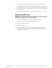
When the plug is not in the center of the plug should not be visible. support.dell.com Dell Latitude CPt V/CPt S Series and CPx H/CPx J Series Service Manual 29 7. Connect the two-wire back-light plug to the top cover. 1. Pull the plug out, turn the plug over, and reinsert ... screws to secure the LCD panel to the connector on the inverter. If you can see Figure 14 and Figure 16). Remove the main battery and secondary battery (if present). 2. Remove the device from the inside of the display assembly top-cover assembly (see the key slot, the plug is all the...
When the plug is not in the center of the plug should not be visible. support.dell.com Dell Latitude CPt V/CPt S Series and CPx H/CPx J Series Service Manual 29 7. Connect the two-wire back-light plug to the top cover. 1. Pull the plug out, turn the plug over, and reinsert ... screws to secure the LCD panel to the connector on the inverter. If you can see Figure 14 and Figure 16). Remove the main battery and secondary battery (if present). 2. Remove the device from the inside of the display assembly top-cover assembly (see the key slot, the plug is all the...
Service Manual
Page 37
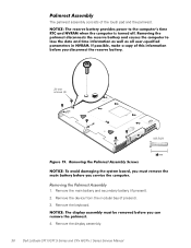
Remove the device from the modular bay (if present). 3. Remove the keyboard. 4. Remove the display assembly. 30 Dell Latitude CPt V/CPt S Series and CPx H/CPx J Series Service Manual Remove the main battery and secondary battery (if present). 2. The palmrest assembly consists of the touch pad and the palmrest. 20-mm screws (5) M2.5x20 1.
Remove the device from the modular bay (if present). 3. Remove the keyboard. 4. Remove the display assembly. 30 Dell Latitude CPt V/CPt S Series and CPx H/CPx J Series Service Manual Remove the main battery and secondary battery (if present). 2. The palmrest assembly consists of the touch pad and the palmrest. 20-mm screws (5) M2.5x20 1.
Service Manual
Page 39
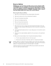
... pad. NOTES: When you replace the reserve battery, first connect the reserve battery cable to the palmrest bracket. 8. Carefully reposition the reserve battery EMI spring clip before securing the two 4-mm palmrest bracket screws. 32 Dell Latitude CPt V/CPt S Series and CPx H/CPx J Series Service Manual 1. Pry the reserve battery free from the palmrest bracket as follows: a. Lift...
... pad. NOTES: When you replace the reserve battery, first connect the reserve battery cable to the palmrest bracket. 8. Carefully reposition the reserve battery EMI spring clip before securing the two 4-mm palmrest bracket screws. 32 Dell Latitude CPt V/CPt S Series and CPx H/CPx J Series Service Manual 1. Pry the reserve battery free from the palmrest bracket as follows: a. Lift...

Service Manual
Page 40
... and washer (see Figure 21). Remove the display assembly. 4. Press the RJ11 connector of the modem assembly into the system board connector. 3. Remove the main battery and secondary battery (if present). 2. Remove the palmrest assembly. 5. support.dell.com Dell Latitude CPt V/CPt S Series and CPx H/CPx J Series Service Manual 33
... and washer (see Figure 21). Remove the display assembly. 4. Press the RJ11 connector of the modem assembly into the system board connector. 3. Remove the main battery and secondary battery (if present). 2. Remove the palmrest assembly. 5. support.dell.com Dell Latitude CPt V/CPt S Series and CPx H/CPx J Series Service Manual 33
Service Manual
Page 41
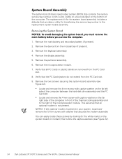
... that outline the captive washers (see Figure 22). Remove the main battery and secondary battery (if present). 2. Remove the palmrest assembly. 6. Remove the keyboard assembly. 4. Remove the two screws securing the system board assembly (see Figure 22). 34 Dell Latitude CPt V/CPt S Series and CPx H/CPx J Series Service Manual The replacement kit for transferring the service...
... that outline the captive washers (see Figure 22). Remove the main battery and secondary battery (if present). 2. Remove the palmrest assembly. 6. Remove the keyboard assembly. 4. Remove the two screws securing the system board assembly (see Figure 22). 34 Dell Latitude CPt V/CPt S Series and CPx H/CPx J Series Service Manual The replacement kit for transferring the service...
Service Manual
Page 43
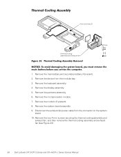
Remove the display assembly. 5. Remove the main battery and secondary battery (if present). 2. Disconnect the exhaust-fan power cable from the modular bay. 3. Remove the palmrest assembly. 6. Remove the keyboard assembly. 4. Remove the modem (if present...4-mm screws securing the thermal cooling assembly and exhaust fan, and then remove the thermal cooling assembly and exhaust fan (see Figure 23). 36 Dell Latitude CPt V/CPt S Series and CPx H/CPx J Series Service Manual Remove the microprocessor module. 7. 4-mm screws (2) thermal cooling assembly and exhaust fan M2.5x4 1.
Remove the display assembly. 5. Remove the main battery and secondary battery (if present). 2. Disconnect the exhaust-fan power cable from the modular bay. 3. Remove the palmrest assembly. 6. Remove the keyboard assembly. 4. Remove the modem (if present...4-mm screws securing the thermal cooling assembly and exhaust fan, and then remove the thermal cooling assembly and exhaust fan (see Figure 23). 36 Dell Latitude CPt V/CPt S Series and CPx H/CPx J Series Service Manual Remove the microprocessor module. 7. 4-mm screws (2) thermal cooling assembly and exhaust fan M2.5x4 1.
Service Manual
Page 44
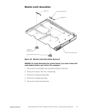
Remove the device from the modular bay. 3. Remove the palmrest assembly. Remove the keyboard assembly. 4. support.dell.com Dell Latitude CPt V/CPt S Series and CPx H/CPx J Series Service Manual 37 Remove the display assembly. 5. Remove the main battery and secondary battery (if present). 2. sliders (2) module latches (2) springs (2) location of snap tabs (2) module latch button (2) bottom case assembly 1.
Remove the device from the modular bay. 3. Remove the palmrest assembly. Remove the keyboard assembly. 4. support.dell.com Dell Latitude CPt V/CPt S Series and CPx H/CPx J Series Service Manual 37 Remove the display assembly. 5. Remove the main battery and secondary battery (if present). 2. sliders (2) module latches (2) springs (2) location of snap tabs (2) module latch button (2) bottom case assembly 1.
Service Manual
Page 46
... 12.1-inch LCD panel inverter removal, 26 replacement, 27 14.1-inch LCD display panel removal, 22 14.1-inch LCD flex cable removal, 22 battery (in modular bay) removal, 12 battery (reserve) removal, 32 CD-ROM drive removal, 12 computer exploded view, 10 working inside, 2 diskette drive removal, 12 display assembly bezel, removal...
... 12.1-inch LCD panel inverter removal, 26 replacement, 27 14.1-inch LCD display panel removal, 22 14.1-inch LCD flex cable removal, 22 battery (in modular bay) removal, 12 battery (reserve) removal, 32 CD-ROM drive removal, 12 computer exploded view, 10 working inside, 2 diskette drive removal, 12 display assembly bezel, removal...

