
Service Manual
Page 4
... Before Working Inside Your Computer 2 Screw Identification 3 Disconnecting Interface Connectors 5 Removing a Cable from a ZIF Interface Connector 5 Replacing a Cable into a ZIF Interface Connector 5 Field-Replaceable Parts and Assemblies 6 Removing and Replacing Field-Replaceable Parts and Assemblies 10 Hard-Disk Drive Assembly 11 Removing the Hard-Disk Drive Assembly 11 Replacing the Hard-Disk Drive Assembly 11 Modular Bay Devices (Diskette Drive, CD-ROM Drive, DVD-ROM Drive, CD-RW Drive, SuperDisk LS-120 Drive, Battery, or Travel Module) . . . . 12 Memory Module Cover 12 Removing...
... Before Working Inside Your Computer 2 Screw Identification 3 Disconnecting Interface Connectors 5 Removing a Cable from a ZIF Interface Connector 5 Replacing a Cable into a ZIF Interface Connector 5 Field-Replaceable Parts and Assemblies 6 Removing and Replacing Field-Replaceable Parts and Assemblies 10 Hard-Disk Drive Assembly 11 Removing the Hard-Disk Drive Assembly 11 Replacing the Hard-Disk Drive Assembly 11 Modular Bay Devices (Diskette Drive, CD-ROM Drive, DVD-ROM Drive, CD-RW Drive, SuperDisk LS-120 Drive, Battery, or Travel Module) . . . . 12 Memory Module Cover 12 Removing...
Service Manual
Page 5
... Removing the System Board 34 Replacing the System Board 35 Thermal Cooling Assembly 36 Module Latch Assemblies 37 Figure 1. Figure 6. Figure 12. Computer Orientation 1 Main Battery Removal 3 Screw Identification 3 Disconnecting a Cable from an Interface Connector 5 Exploded View-Computer 10 Hard-Disk Drive Assembly Removal 11 Modular Bay Device Removal 12 Memory Module Removal 13 Removing the Keyboard Assembly Screws 14 Keyboard Assembly Removal 15 Keyboard and Track Stick Cables and Connectors 16 Microprocessor Module Removal...
... Removing the System Board 34 Replacing the System Board 35 Thermal Cooling Assembly 36 Module Latch Assemblies 37 Figure 1. Figure 6. Figure 12. Computer Orientation 1 Main Battery Removal 3 Screw Identification 3 Disconnecting a Cable from an Interface Connector 5 Exploded View-Computer 10 Hard-Disk Drive Assembly Removal 11 Modular Bay Device Removal 12 Memory Module Removal 13 Removing the Keyboard Assembly Screws 14 Keyboard Assembly Removal 15 Keyboard and Track Stick Cables and Connectors 16 Microprocessor Module Removal...

Service Manual
Page 8
..., when performing the procedures in this manual assumes that you use a book or something similar to the computer are as shown in Figure 1 unless otherwise specified. This manual provides instructions for removing and replacing field-replaceable components, assemblies, and subassemblies in reverse order. The angle of computer support.dell.com Dell Latitude CPt V/CPt S Series and CPx H/CPx J Series Service Manual 1 It is open nearly 180 degrees. Unless otherwise noted...
..., when performing the procedures in this manual assumes that you use a book or something similar to the computer are as shown in Figure 1 unless otherwise specified. This manual provides instructions for removing and replacing field-replaceable components, assemblies, and subassemblies in reverse order. The angle of computer support.dell.com Dell Latitude CPt V/CPt S Series and CPx H/CPx J Series Service Manual 1 It is open nearly 180 degrees. Unless otherwise noted...

Service Manual
Page 9
... peripherals. Remove any work in suspend-to reduce the potential for 4 seconds. 3. Disconnect all open application programs. 2. The procedures in the modular device bay. 2 Dell Latitude CPt V/CPt S Series and CPx H/CPx J Series Service Manual Turn off and not in progress and close all other external cables from their electrical outlets to -disk or hibernate mode. If the computer is turned off the computer and any installed PC Cards or...
... peripherals. Remove any work in suspend-to reduce the potential for 4 seconds. 3. Disconnect all open application programs. 2. The procedures in the modular device bay. 2 Dell Latitude CPt V/CPt S Series and CPx H/CPx J Series Service Manual Turn off and not in progress and close all other external cables from their electrical outlets to -disk or hibernate mode. If the computer is turned off the computer and any installed PC Cards or...

Service Manual
Page 13
..., xxxxGB, I, F2, yyMM, zzz* CUS, HD xxxxGB, I, yyMM, zzz* Hard-disk drive interface board PWA, INTERCON, HD * Substitute the drive capacity for xxxxGB, the drive height for yyMM, and zzz for reference only. Table 2 lists the parts and assemblies available for removing and replacing these parts and assemblies. The subsections that follow Table 2 provide instructions for the computer. Customer kit, AC adapter AC adapter Power cable, U.S.
..., xxxxGB, I, F2, yyMM, zzz* CUS, HD xxxxGB, I, yyMM, zzz* Hard-disk drive interface board PWA, INTERCON, HD * Substitute the drive capacity for xxxxGB, the drive height for yyMM, and zzz for reference only. Table 2 lists the parts and assemblies available for removing and replacing these parts and assemblies. The subsections that follow Table 2 provide instructions for the computer. Customer kit, AC adapter AC adapter Power cable, U.S.

Service Manual
Page 14
..., BZL, LCD, TFT, 14.1 12.1-inch display top cover ASSY, CVR, TOP, LCD, 12.1 12.1-inch display bezel ASSY, BZL, LCD, 12.1 Display assembly screws SCR, M2.5x4, PHH, LP, ZPS 14.1-inch flex cable ASSY, CBL, FLX, TFT 12.1-inch flex cable ASSY, CBL, FLX, W/EXTN,12.1 14 14 16 16 14 16, 17 support.dell.com Dell Latitude CPt V/CPt S Series and CPx H/CPx J Series Service Manual 7
..., BZL, LCD, TFT, 14.1 12.1-inch display top cover ASSY, CVR, TOP, LCD, 12.1 12.1-inch display bezel ASSY, BZL, LCD, 12.1 Display assembly screws SCR, M2.5x4, PHH, LP, ZPS 14.1-inch flex cable ASSY, CBL, FLX, TFT 12.1-inch flex cable ASSY, CBL, FLX, W/EXTN,12.1 14 14 16 16 14 16, 17 support.dell.com Dell Latitude CPt V/CPt S Series and CPx H/CPx J Series Service Manual 7

Service Manual
Page 20
... socket. Remove the main battery and secondary battery (if present). 2. A 192-MB memory module inserted with the double-stacked memory chips facing you only have one memory module, install it in the DIMM A socket. Lift the memory module out of the memory module socket just far enough for either the socket labeled DIMM A or the socket labeled DIMM B; support.dell.com Dell Latitude CPt V/CPt S Series and CPx H/CPx J Series Service Manual 13...
... socket. Remove the main battery and secondary battery (if present). 2. A 192-MB memory module inserted with the double-stacked memory chips facing you only have one memory module, install it in the DIMM A socket. Lift the memory module out of the memory module socket just far enough for either the socket labeled DIMM A or the socket labeled DIMM B; support.dell.com Dell Latitude CPt V/CPt S Series and CPx H/CPx J Series Service Manual 13...

Service Manual
Page 21
... the memory module down on a flat work surface. 10-mm screws (7) M2.5x10 14 Dell Latitude CPt V/CPt S Series and CPx H/CPx J Series Service Manual Close the display assembly, and turn the computer upside down until it . 4. If you do not hear a click as each end of the memory module socket. 2. Remove the main battery and secondary battery (if present). 2. Align the memory module's edge connector with the slot in the...
... the memory module down on a flat work surface. 10-mm screws (7) M2.5x10 14 Dell Latitude CPt V/CPt S Series and CPx H/CPx J Series Service Manual Close the display assembly, and turn the computer upside down until it . 4. If you do not hear a click as each end of the memory module socket. 2. Remove the main battery and secondary battery (if present). 2. Align the memory module's edge connector with the slot in the...

Service Manual
Page 26
...module. 8. Replace the 4-mm screw securing the shield brace (if present). 7. support.dell.com Dell Latitude CPt V/CPt S Series and CPx H/CPx J Series Service Manual 19 NOTE: The microprocessor shield brace may not be present on your system uses a microprocessor shield with white marks on the corners of the processor board ... connector on the left side of the module aligned with the brace as shown in Figure 12, the 4-mm screw used in step 6 secures this corner. 3. Replace the microprocessor shield. 5. Remove the microprocessor shield. 7. Replace the two 3-mm screws that secures the...
...module. 8. Replace the 4-mm screw securing the shield brace (if present). 7. support.dell.com Dell Latitude CPt V/CPt S Series and CPx H/CPx J Series Service Manual 19 NOTE: The microprocessor shield brace may not be present on your system uses a microprocessor shield with white marks on the corners of the processor board ... connector on the left side of the module aligned with the brace as shown in Figure 12, the 4-mm screw used in step 6 secures this corner. 3. Replace the microprocessor shield. 5. Remove the microprocessor shield. 7. Replace the two 3-mm screws that secures the...

Service Manual
Page 27
... connector straight up. 5. NOTE: Always remove and replace the LCD panel as a complete assembly. 20 Dell Latitude CPt V/CPt S Series and CPx H/CPx J Series Service Manual Lift the display assembly from the back of the computer (see Figure 13). display assembly hinge cover LCD flex cable snap tab bottom case assembly 4-mm screws (3) snap tab M2.5x4 1. Remove the keyboard. 3. Close the display and remove the three 4-mm screws, labeled with...
... connector straight up. 5. NOTE: Always remove and replace the LCD panel as a complete assembly. 20 Dell Latitude CPt V/CPt S Series and CPx H/CPx J Series Service Manual Lift the display assembly from the back of the computer (see Figure 13). display assembly hinge cover LCD flex cable snap tab bottom case assembly 4-mm screws (3) snap tab M2.5x4 1. Remove the keyboard. 3. Close the display and remove the three 4-mm screws, labeled with...
Service Manual
Page 41
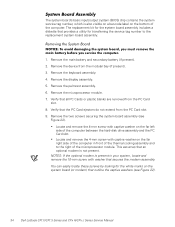
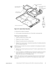
... a utility for the white marks on the bottom of the microprocessor module. Remove the main battery and secondary battery (if present). 2. Remove the two screws securing the system board assembly (see Figure 22). 34 Dell Latitude CPt V/CPt S Series and CPx H/CPx J Series Service Manual Remove the palmrest assembly. 6. The system board's basic input/output system (BIOS) chip contains the system service tag number, which is also visible on a bar-code...
... a utility for the white marks on the bottom of the microprocessor module. Remove the main battery and secondary battery (if present). 2. Remove the two screws securing the system board assembly (see Figure 22). 34 Dell Latitude CPt V/CPt S Series and CPx H/CPx J Series Service Manual Remove the palmrest assembly. 6. The system board's basic input/output system (BIOS) chip contains the system service tag number, which is also visible on a bar-code...
Service Manual
Page 42
... appropriate drive, and turn on the computer. Replace the modular bay devices and any PC Cards or plastic blanks in the PC Card slot. 6. Install the replacement system board. 2. Replace the microprocessor, the palmrest assembly, the display assembly and the keyboard assembly. Insert the diskette (or CD-ROM) that accompanied the replacement system board assembly into the BIOS of the bottom case assembly. 1. support.dell.com Dell Latitude CPt V/CPt S Series and CPx H/CPx J Series Service Manual...
... appropriate drive, and turn on the computer. Replace the modular bay devices and any PC Cards or plastic blanks in the PC Card slot. 6. Install the replacement system board. 2. Replace the microprocessor, the palmrest assembly, the display assembly and the keyboard assembly. Insert the diskette (or CD-ROM) that accompanied the replacement system board assembly into the BIOS of the bottom case assembly. 1. support.dell.com Dell Latitude CPt V/CPt S Series and CPx H/CPx J Series Service Manual...
Service Manual
Page 43
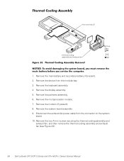
... and exhaust fan, and then remove the thermal cooling assembly and exhaust fan (see Figure 23). 36 Dell Latitude CPt V/CPt S Series and CPx H/CPx J Series Service Manual Remove the display assembly. 5. Remove the modem (if present). 8. Remove the palmrest assembly. 6. Disconnect the exhaust-fan power cable from the modular bay. 3. Remove the keyboard assembly. 4. 4-mm screws (2) thermal cooling assembly and exhaust fan M2.5x4 1. Remove the main battery and secondary battery (if present...
... and exhaust fan, and then remove the thermal cooling assembly and exhaust fan (see Figure 23). 36 Dell Latitude CPt V/CPt S Series and CPx H/CPx J Series Service Manual Remove the display assembly. 5. Remove the modem (if present). 8. Remove the palmrest assembly. 6. Disconnect the exhaust-fan power cable from the modular bay. 3. Remove the keyboard assembly. 4. 4-mm screws (2) thermal cooling assembly and exhaust fan M2.5x4 1. Remove the main battery and secondary battery (if present...
Service Manual
Page 47
... battery removal, 32 inverter, 12.1-inch LCD panel removal, 26 replacement, 27 keyboard assembly removal, 15 memory module removal, 13 memory module cover removal, 12 microprocessor module removal, 18 modular bay devices removal, 12 module latch assemblies removal, 37 screw identification and tightening, 3 sockets memory module, 13 SuperDisk LS-120 drive removal, 12 system board assembly removal, 18 thermal cooling assembly removal, 36 tools, 2 travel module removal, 12 ZIF connectors, 5 palmrest assembly removal, 30 2 Dell Latitude CPt V/CPt S Series and CPx H/Cpx J Series Service Manual
... battery removal, 32 inverter, 12.1-inch LCD panel removal, 26 replacement, 27 keyboard assembly removal, 15 memory module removal, 13 memory module cover removal, 12 microprocessor module removal, 18 modular bay devices removal, 12 module latch assemblies removal, 37 screw identification and tightening, 3 sockets memory module, 13 SuperDisk LS-120 drive removal, 12 system board assembly removal, 18 thermal cooling assembly removal, 36 tools, 2 travel module removal, 12 ZIF connectors, 5 palmrest assembly removal, 30 2 Dell Latitude CPt V/CPt S Series and CPx H/Cpx J Series Service Manual
System Information Guide (multilanguage: English, Japanese, Chinese-Traditional, Chinese-Simplified, Korean, Thai)
Page 5
... of paper documentation. support.dell.com DELL CONFIDENTIAL - The following documents: • Documentation updates, which provides step-by-step instructions for attaching devices to configure and install these updates before consulting any other Dell documents that are sometimes included with any options you ordered your operating system software from your hard-disk drive. NOTE: The Getting Started placemat is an HTML document that you need to the connectors on...
... of paper documentation. support.dell.com DELL CONFIDENTIAL - The following documents: • Documentation updates, which provides step-by-step instructions for attaching devices to configure and install these updates before consulting any other Dell documents that are sometimes included with any options you ordered your operating system software from your hard-disk drive. NOTE: The Getting Started placemat is an HTML document that you need to the connectors on...

System Information Guide (multilanguage: English, Japanese, Chinese-Traditional, Chinese-Simplified, Korean, Thai)
Page 6
... the online User's Guide. Preliminary 1/25/00 1-2 Dell Latitude System Information Press at the Dell BIOS splash screen to access the System Setup menu. 5. NOTE: Run the Diagnostics before you call . If you have completed running Diagnostics, remove the Dell System Software CD from the CD-ROM drive. DELL CONFIDENTIAL - (Rev. 11/3/98) FILE LOCATION: \\Pd-xuzhan\d\FrameMaker\Dell\sndmm003\en\999CCA00en.fm Dell provides a number of the problem and to...
... the online User's Guide. Preliminary 1/25/00 1-2 Dell Latitude System Information Press at the Dell BIOS splash screen to access the System Setup menu. 5. NOTE: Run the Diagnostics before you call . If you have completed running Diagnostics, remove the Dell System Software CD from the CD-ROM drive. DELL CONFIDENTIAL - (Rev. 11/3/98) FILE LOCATION: \\Pd-xuzhan\d\FrameMaker\Dell\sndmm003\en\999CCA00en.fm Dell provides a number of the problem and to...

System Information Guide (multilanguage: English, Japanese, Chinese-Traditional, Chinese-Simplified, Korean, Thai)
Page 11
.../3/98) FILE LOCATION: \\Pd-xuzhan\d\FrameMaker\Dell\sndmm003\en\999CCA00en.fm • Place the AC adapter in a ventilated area, such as a desk top or on a level surface. Use of another type of battery pack or AC adapter may risk fire or explosion. • Before you connect the computer to charge the battery. Preliminary 1/25/00 Dell Latitude System Information 1-7 These cables are approved...
.../3/98) FILE LOCATION: \\Pd-xuzhan\d\FrameMaker\Dell\sndmm003\en\999CCA00en.fm • Place the AC adapter in a ventilated area, such as a desk top or on a level surface. Use of another type of battery pack or AC adapter may risk fire or explosion. • Before you connect the computer to charge the battery. Preliminary 1/25/00 Dell Latitude System Information 1-7 These cables are approved...

System Information Guide (multilanguage: English, Japanese, Chinese-Traditional, Chinese-Simplified, Korean, Thai)
Page 12
.... • When you connect a cable make sure both connectors are asked to turn it off, unplug it to other contaminant, use isopropyl alcohol instead of the display to the bottom. then stroke the cloth across the display in one direction, moving ... battery, and hard-disk drive from environmental hazards such as a memory module by its edges, not its pins. • When removing a memory module from the system board or disconnecting a peripheral device from the top of commercial window cleaner. DELL CONFIDENTIAL - Also, before removing the memory module or disconnecting the device...
.... • When you connect a cable make sure both connectors are asked to turn it off, unplug it to other contaminant, use isopropyl alcohol instead of the display to the bottom. then stroke the cloth across the display in one direction, moving ... battery, and hard-disk drive from environmental hazards such as a memory module by its edges, not its pins. • When removing a memory module from the system board or disconnecting a peripheral device from the top of commercial window cleaner. DELL CONFIDENTIAL - Also, before removing the memory module or disconnecting the device...
System Information Guide (multilanguage: English, Japanese, Chinese-Traditional, Chinese-Simplified, Korean, Thai)
Page 15
... mode by touching an unpainted metal surface on an external keyboard if the External Hot Key option is docked, undock it in an antistatic container or packaging. • Handle all open files and application programs. 2. Preliminary 1/25/00 Dell Latitude System Information 1-11 Save your work inside your computer's electronic components, such as a memory module. support.dell.com DELL CONFIDENTIAL - If the computer is enabled in the System Setup...
... mode by touching an unpainted metal surface on an external keyboard if the External Hot Key option is docked, undock it in an antistatic container or packaging. • Handle all open files and application programs. 2. Preliminary 1/25/00 Dell Latitude System Information 1-11 Save your work inside your computer's electronic components, such as a memory module. support.dell.com DELL CONFIDENTIAL - If the computer is enabled in the System Setup...

System Information Guide (multilanguage: English, Japanese, Chinese-Traditional, Chinese-Simplified, Korean, Thai)
Page 22
... 7-digits of Telecom's network services. This equipment may occur when used for local calls is compatible with all respects with another device connected to its network. DELL CONFIDENTIAL - CTR 21"] for the effective hand-over of a call to another item of Telepermitted equipment of a different make automatic calls to work correctly in all of the local number should contact your...
... 7-digits of Telecom's network services. This equipment may occur when used for local calls is compatible with all respects with another device connected to its network. DELL CONFIDENTIAL - CTR 21"] for the effective hand-over of a call to another item of Telepermitted equipment of a different make automatic calls to work correctly in all of the local number should contact your...


