Handling swollen Lithium-ion batteries
Page 1
...for a slim form factor (especially with a compatible battery purchased from Dell that is designed to lithium-ion polymer battery technology is the potential for swelling of the battery cells Swollen battery may impact the performance of lithium-ion battery is fully discharged. ● Do not crush,...to comply with your Dell computer. Swollen batteries should not be used and should be returned to Dell in a device as a result of Dell Inc. To discharge the battery, unplug the AC adapter from Dell. 1 Always purchase genuine batteries from https://www.dell.com or otherwise ...
...for a slim form factor (especially with a compatible battery purchased from Dell that is designed to lithium-ion polymer battery technology is the potential for swelling of the battery cells Swollen battery may impact the performance of lithium-ion battery is fully discharged. ● Do not crush,...to comply with your Dell computer. Swollen batteries should not be used and should be returned to Dell in a device as a result of Dell Inc. To discharge the battery, unplug the AC adapter from Dell. 1 Always purchase genuine batteries from https://www.dell.com or otherwise ...

Handling swollen Lithium-ion batteries
Page 2
Frequently Asked Questions. 2 For more information on how to improve the performance and lifespan of the laptop battery and to minimize the possibility of occurrence of charge cycles, or exposure to high heat. Lithium-ion batteries can swell for various reasons such as age, number of the issue, see Dell Laptop Battery -
Frequently Asked Questions. 2 For more information on how to improve the performance and lifespan of the laptop battery and to minimize the possibility of occurrence of charge cycles, or exposure to high heat. Lithium-ion batteries can swell for various reasons such as age, number of the issue, see Dell Laptop Battery -

Quick Start Guide - Windows 7
Page 2
...; 13. 具 PowerShare 的 USB 3.0 連接埠 14. Camera status light (optional) 5. Dual array microphones 10. SD 23. USB 3.0 ポート 8 9 10 11. Battery charge status light 18. USB 3.0 port 24. Nobel Wedge 12. Power connector port 9. HDMI 端口 7. DisplayPort(带 Type-C 选的 Thunderbolt™ 3 25...
...; 13. 具 PowerShare 的 USB 3.0 連接埠 14. Camera status light (optional) 5. Dual array microphones 10. SD 23. USB 3.0 ポート 8 9 10 11. Battery charge status light 18. USB 3.0 port 24. Nobel Wedge 12. Power connector port 9. HDMI 端口 7. DisplayPort(带 Type-C 选的 Thunderbolt™ 3 25...

Owners Manual
Page 3
SSD...15 Hard drive...15 Removing hard drive assembly...15 Installing the hard drive assembly...16 Coin cell battery...16 Removing the coin cell battery...16 Installing the coin cell battery...17 WLAN card...18 Removing the WLAN card...18 Installing the WLAN card...18 WWAN card...19 Removing the WWAN card...19... Identification Module card 10 Removing the Subscriber Identification Module card 10 Base cover...11 Removing the base cover...11 Installing the base cover...12 Battery...12 Lithium-ion battery precautions...12 Removing the battery...13 Installing the battery...13 Solid State Drive -
SSD...15 Hard drive...15 Removing hard drive assembly...15 Installing the hard drive assembly...16 Coin cell battery...16 Removing the coin cell battery...16 Installing the coin cell battery...17 WLAN card...18 Removing the WLAN card...18 Installing the WLAN card...18 WWAN card...19 Removing the WWAN card...19... Identification Module card 10 Removing the Subscriber Identification Module card 10 Base cover...11 Removing the base cover...11 Installing the base cover...12 Battery...12 Lithium-ion battery precautions...12 Removing the battery...13 Installing the battery...13 Solid State Drive -

Owners Manual
Page 6
... Camera specifications...85 Communication specifications...86 Port and connector specifications...86 Contactless smart card specifications...86 Display specifications...87 Keyboard specifications...87 Touchpad specifications...88 Battery specifications...88 AC Adapter specifications...89 Physical specifications...89 Environmental specifications...90 6 Contents
... Camera specifications...85 Communication specifications...86 Port and connector specifications...86 Contactless smart card specifications...86 Display specifications...87 Keyboard specifications...87 Touchpad specifications...88 Battery specifications...88 AC Adapter specifications...89 Physical specifications...89 Environmental specifications...90 6 Contents

Owners Manual
Page 7
ePSA diagnostics 93 LAN status LED...94 Real Time Clock reset...94 7 Contacting Dell...96 Contents 7 6 Diagnostics...91 Enhanced Pre-Boot System Assessment ePSA diagnostics 91 Device status lights...92 Battery status lights...93 Troubleshooting...93 Enhanced Pre-Boot System Assessment -
ePSA diagnostics 93 LAN status LED...94 Real Time Clock reset...94 7 Contacting Dell...96 Contents 7 6 Diagnostics...91 Enhanced Pre-Boot System Assessment ePSA diagnostics 91 Device status lights...92 Battery status lights...93 Troubleshooting...93 Enhanced Pre-Boot System Assessment -
Owners Manual
Page 9
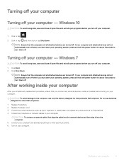
...off your computer 9 If your computer and attached devices did not automatically turn off when you turn them off. Do not use only the battery designed for about 6 seconds to your computer. Windows 7 CAUTION: To avoid losing data, save and close all open files and exit ...into the network device and then plug it into the computer. 5 Connect your operating system, press and hold the power button for other Dell computers. 1 Replace the battery. 2 Replace the base cover. 3 Connect any external devices, such as a port replicator or media base, and replace any cards, such...
...off your computer 9 If your computer and attached devices did not automatically turn off when you turn them off. Do not use only the battery designed for about 6 seconds to your computer. Windows 7 CAUTION: To avoid losing data, save and close all open files and exit ...into the network device and then plug it into the computer. 5 Connect your operating system, press and hold the power button for other Dell computers. 1 Replace the battery. 2 Replace the base cover. 3 Connect any external devices, such as a port replicator or media base, and replace any cards, such...

Owners Manual
Page 12
... free it as possible before removing it from the system. Contact https://www.dell.com/support for assistance and further instructions. • Always purchase genuine batteries from https://www.dell.com or authorized Dell partners and re-sellers. 12 Removing and installing components Installing the base cover 1 Align the base cover with foreign objects...
... free it as possible before removing it from the system. Contact https://www.dell.com/support for assistance and further instructions. • Always purchase genuine batteries from https://www.dell.com or authorized Dell partners and re-sellers. 12 Removing and installing components Installing the base cover 1 Align the base cover with foreign objects...

Owners Manual
Page 13
... from the connector on the system board. 3 Tighten the M2.5x5 screw to secure the battery to the computer [2]. Installing the battery NOTE: the 92Whr battery requires the use of a M.2 card and a 68Whr battery can use of a M.2 card and a 68Whr battery can be used with either a M.2 or 7mm SATA drive. 1 Follow the procedure in After...
... from the connector on the system board. 3 Tighten the M2.5x5 screw to secure the battery to the computer [2]. Installing the battery NOTE: the 92Whr battery requires the use of a M.2 card and a 68Whr battery can use of a M.2 card and a 68Whr battery can be used with either a M.2 or 7mm SATA drive. 1 Follow the procedure in After...
Owners Manual
Page 14
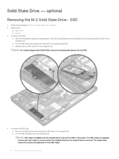
SSD 1 Follow the procedure in Before working inside your computer. 2 Remove the: a base cover b battery 3 To remove the SSD: a Peel off the adhesive tape that is placed above the SSD card [1].Remove the one M2x3 screw [1] that needs to be ...
SSD 1 Follow the procedure in Before working inside your computer. 2 Remove the: a base cover b battery 3 To remove the SSD: a Peel off the adhesive tape that is placed above the SSD card [1].Remove the one M2x3 screw [1] that needs to be ...

Owners Manual
Page 15
... the adhesive tape following the SSD card. NOTE: For models shipped with NVMe SSDs, the SSD requires installation of a thermal plate over it. 6 Install the: a battery b base cover 7 Follow the procedure in . 1 Place the SSD clip on the computer . 2 Tighten the M2x3 screw that the... battery is fully charged or the power cable is plugged in After working inside your computer. 2 Remove the: Removing and installing components 15 Hard drive Removing ...
... the adhesive tape following the SSD card. NOTE: For models shipped with NVMe SSDs, the SSD requires installation of a thermal plate over it. 6 Install the: a battery b base cover 7 Follow the procedure in . 1 Place the SSD clip on the computer . 2 Tighten the M2x3 screw that the... battery is fully charged or the power cable is plugged in After working inside your computer. 2 Remove the: Removing and installing components 15 Hard drive Removing ...

Owners Manual
Page 16
...Disconnect the hard drive cable from the computer [3]. c Lift the hard drive assembly away from the connector on the system board. 4 Install the: a battery b base cover 5 Follow the procedures in Before working inside your system. Installing the hard drive assembly NOTE: 7mm SATA drive requires a 68Whr... battery. 1 Insert the hard drive assembly into the slot on the computer. 2 Tighten the screws to secure the hard drive assembly to the ...
...Disconnect the hard drive cable from the computer [3]. c Lift the hard drive assembly away from the connector on the system board. 4 Install the: a battery b base cover 5 Follow the procedures in Before working inside your system. Installing the hard drive assembly NOTE: 7mm SATA drive requires a 68Whr... battery. 1 Insert the hard drive assembly into the slot on the computer. 2 Tighten the screws to secure the hard drive assembly to the ...

Owners Manual
Page 17
... [1]. Removing and installing components 17 b Pry the coin cell battery to avoid damaging the cable. 3 Install the: a chassis frame b battery c base cover 4 Follow the procedure in After working inside your computer. a base cover b battery 3 To remove the coin cell battery: a Disconnect the coin cell battery cable from the system board [2]. NOTE: Route the coin cell...
... [1]. Removing and installing components 17 b Pry the coin cell battery to avoid damaging the cable. 3 Install the: a chassis frame b battery c base cover 4 Follow the procedure in After working inside your computer. a base cover b battery 3 To remove the coin cell battery: a Disconnect the coin cell battery cable from the system board [2]. NOTE: Route the coin cell...

Owners Manual
Page 18
... the system board/chassis frame during the prying process. If the adhesive pad is held in Before working inside your computer. 2 Remove the: a base cover b battery 3 To remove the WLAN card: a Remove the M2x3 screw that secures the WLAN cables to the WLAN card [2]. When removing the wireless card from the...
... the system board/chassis frame during the prying process. If the adhesive pad is held in Before working inside your computer. 2 Remove the: a base cover b battery 3 To remove the WLAN card: a Remove the M2x3 screw that secures the WLAN cables to the WLAN card [2]. When removing the wireless card from the...

Owners Manual
Page 19
... from the connector. WWAN card Removing the WWAN card 1 Follow the procedure in Before working inside your computer. 2 Remove the: a base cover b battery 3 To remove the memory module: a Pry the clips securing the memory module until the memory pops-up [1]. Installing the WWAN card 1 Insert the... card into the routing channels on the chassis frame. 3 Connect the WLAN cables to the connectors on the WWAN Card. 4 Install the: a battery b base cover 5 Follow the procedure in After working inside your system. NOTE: When installing the display assembly or chassis frame onto the system, ...
... from the connector. WWAN card Removing the WWAN card 1 Follow the procedure in Before working inside your computer. 2 Remove the: a base cover b battery 3 To remove the memory module: a Pry the clips securing the memory module until the memory pops-up [1]. Installing the WWAN card 1 Insert the... card into the routing channels on the chassis frame. 3 Connect the WLAN cables to the connectors on the WWAN Card. 4 Install the: a battery b base cover 5 Follow the procedure in After working inside your system. NOTE: When installing the display assembly or chassis frame onto the system, ...

Owners Manual
Page 20
Installing the memory module 1 Insert the memory module into the memory module socket then press downward until the clips secure the memory module. 2 Install the: a battery b base cover 3 Follow the procedures in Before working inside your computer. Keyboard Removing the keyboard trim 1 Follow the procedure in After working inside your computer. 2 Pry the keyboard trim from the edges [1] and lift it away from the computer [2]. 20 Removing and installing components
Installing the memory module 1 Insert the memory module into the memory module socket then press downward until the clips secure the memory module. 2 Install the: a battery b base cover 3 Follow the procedures in Before working inside your computer. Keyboard Removing the keyboard trim 1 Follow the procedure in After working inside your computer. 2 Pry the keyboard trim from the edges [1] and lift it away from the computer [2]. 20 Removing and installing components

Owners Manual
Page 21
NOTE: You may need a plastic scribe to pry the keyboard trim from the connector. Removing the keyboard 1 Follow the procedure in Before working inside your computer. 2 Remove the: a base cover b battery c keyboard trim 3 Lift the latch, and disconnect the keyboard cable [1], touchpad cable [2], trackstick cable [3] and back light(optional) [4] from the edges. Removing and installing components 21
NOTE: You may need a plastic scribe to pry the keyboard trim from the connector. Removing the keyboard 1 Follow the procedure in Before working inside your computer. 2 Remove the: a base cover b battery c keyboard trim 3 Lift the latch, and disconnect the keyboard cable [1], touchpad cable [2], trackstick cable [3] and back light(optional) [4] from the edges. Removing and installing components 21

Owners Manual
Page 24
... inside your system. 24 Removing and installing components Installing the keyboard 1 Align the keyboard with the tabs on the system board. 4 Install the: a keyboard trim b battery c base cover 5 Follow the procedure in After working inside your system.
... inside your system. 24 Removing and installing components Installing the keyboard 1 Align the keyboard with the tabs on the system board. 4 Install the: a keyboard trim b battery c base cover 5 Follow the procedure in After working inside your system.

Owners Manual
Page 25
... sink to the connector on the system board in After working inside your computer. 2 Remove the: a base cover b battery 3 To remove the heat sink - : a [1]. NOTE: Tighten the screws on the system board. 4 Install the: a battery b base cover 5 Follow the procedure in the order of the callout numbers [1, 2, 3, 4, 5, 6]. 3 Connect the fan cable to...
... sink to the connector on the system board in After working inside your computer. 2 Remove the: a base cover b battery 3 To remove the heat sink - : a [1]. NOTE: Tighten the screws on the system board. 4 Install the: a battery b base cover 5 Follow the procedure in the order of the callout numbers [1, 2, 3, 4, 5, 6]. 3 Connect the fan cable to...

Owners Manual
Page 26
b Remove the M2x3 screws (2) that secures the system fan to the connector on the system board. 4 Install the: a battery b base cover 5 Follow the procedure in Before working inside your computer. 26 Removing and installing components Installing the system fan 1 Place the system fan on ... a integrated heat sink and system fan. System fan Removing the system fan 1 Follow the procedure in After working inside your computer. 2 Remove the: a base cover b battery 3 To remove the system fan: a Disconnect the system fan cable from the system board [2].
b Remove the M2x3 screws (2) that secures the system fan to the connector on the system board. 4 Install the: a battery b base cover 5 Follow the procedure in Before working inside your computer. 26 Removing and installing components Installing the system fan 1 Place the system fan on ... a integrated heat sink and system fan. System fan Removing the system fan 1 Follow the procedure in After working inside your computer. 2 Remove the: a base cover b battery 3 To remove the system fan: a Disconnect the system fan cable from the system board [2].


