Service Manual
Page 1
... and Windows are either the entities claiming the marks and names or their products. February 2009 Rev. Dell™ Inspiron™ 535/537/545/546 Service Manual Technical Overview Before You Begin Computer Cover Front Bezel Memory PCI and PCI Express Cards Drives Models DCME and DCMF Fans Front I/O Panel Processor System Board Power...
... and Windows are either the entities claiming the marks and names or their products. February 2009 Rev. Dell™ Inspiron™ 535/537/545/546 Service Manual Technical Overview Before You Begin Computer Cover Front Bezel Memory PCI and PCI Express Cards Drives Models DCME and DCMF Fans Front I/O Panel Processor System Board Power...
Service Manual
Page 26
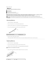
... with the tab in the connector. 1 cutouts (2) 2 tab If the memory module is difficult to remove, gently ease the memory module back and forth to Contents Page Memory Dell™ Inspiron™ 535/537/545/546 Service Manual Removing Memory Replacing Memory Recommended Memory Configuration Setting Up Dual Channel Memory Configuration WARNING: Before working inside your computer, read the safety...
... with the tab in the connector. 1 cutouts (2) 2 tab If the memory module is difficult to remove, gently ease the memory module back and forth to Contents Page Memory Dell™ Inspiron™ 535/537/545/546 Service Manual Removing Memory Replacing Memory Recommended Memory Configuration Setting Up Dual Channel Memory Configuration WARNING: Before working inside your computer, read the safety...
Service Manual
Page 27
... computer cover (see Replacing the Computer Cover). 7. Log on Inspiron™ 535/537. If the message appears stating that the memory is not supported on to continue. 8. Connect your Microsoft® Windows® desktop and click Properties. 10. Recommended Memory Configuration While installing or replacing memory, refer to electrical outlets, and then turn them on...
... computer cover (see Replacing the Computer Cover). 7. Log on Inspiron™ 535/537. If the message appears stating that the memory is not supported on to continue. 8. Connect your Microsoft® Windows® desktop and click Properties. 10. Recommended Memory Configuration While installing or replacing memory, refer to electrical outlets, and then turn them on...

Service Manual
Page 28
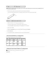
1 Pair A: matched pair of memory 2 Pair B: matched pair of memory modules in connectors DIMM1 and modules in connectors DIMM2 and DIMM3 DIMM4 Inspiron 546 1 Pair B: matched pair of memory 2 Pair A: matched pair of memory modules in connectors DIMM3 and modules in connectors DIMM1 and DIMM4 DIMM2 Back to Contents Page
1 Pair A: matched pair of memory 2 Pair B: matched pair of memory modules in connectors DIMM1 and modules in connectors DIMM2 and DIMM3 DIMM4 Inspiron 546 1 Pair B: matched pair of memory 2 Pair A: matched pair of memory modules in connectors DIMM3 and modules in connectors DIMM1 and DIMM4 DIMM2 Back to Contents Page
Service Manual
Page 31
... down for the computer, if present. This field appears on (or restart) your computer. Back to Contents Page System Setup Dell™ Inspiron™ 535/537/545/546 Service Manual Overview Entering System Setup Clearing Forgotten Passwords Clearing CMOS Settings Flashing the BIOS Overview Use System Setup: l ...any hardware in your computer. 2. l To set the type of your computer and try again. l To read the current amount of memory or set or change the settings in system setup unless you use System Setup, it is held down your computer, including installed hardware, ...
... down for the computer, if present. This field appears on (or restart) your computer. Back to Contents Page System Setup Dell™ Inspiron™ 535/537/545/546 Service Manual Overview Entering System Setup Clearing Forgotten Passwords Clearing CMOS Settings Flashing the BIOS Overview Use System Setup: l ...any hardware in your computer. 2. l To set the type of your computer and try again. l To read the current amount of memory or set or change the settings in system setup unless you use System Setup, it is held down your computer, including installed hardware, ...
Service Manual
Page 32
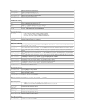
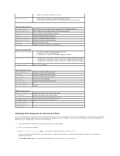
...MB, MAX (128 MB by default) Module Bay Identifies the device installed in the format (hh:mm:ss). Indicates the frequency of installed memory. Disabled (Disabled by default) Hard Drive; Network; Network; CD/DVD; S3(STR) (S3(STR) by default) l Execute Disable ... Used to set the device priority of network devices. Used to set the device priority of installed memory. Standard CMOS Features Date Displays current date in Inspiron 537 Integrated Peripherals USB Device Setting l USB Controller-Enabled or Disabled (Enabled by default) Advanced BIOS Features...
...MB, MAX (128 MB by default) Module Bay Identifies the device installed in the format (hh:mm:ss). Indicates the frequency of installed memory. Disabled (Disabled by default) Hard Drive; Network; Network; CD/DVD; S3(STR) (S3(STR) by default) l Execute Disable ... Used to set the device priority of network devices. Used to set the device priority of installed memory. Standard CMOS Features Date Displays current date in Inspiron 537 Integrated Peripherals USB Device Setting l USB Controller-Enabled or Disabled (Enabled by default) Advanced BIOS Features...
Service Manual
Page 33
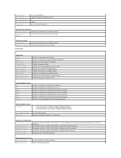
... in the format (hh:mm:ss). Displays the SATA drives connected to change the user password Inspiron 545 System Info System BIOS Info Service Tag Processor Type Processor L2 Cache Memory Installed Memory Available Memory Speed Memory Channel Mode Memory Technology Displays the computer model number. Disabled (Enabled by default) Set Supervisor Password Supervisor Password Installed...
... in the format (hh:mm:ss). Displays the SATA drives connected to change the user password Inspiron 545 System Info System BIOS Info Service Tag Processor Type Processor L2 Cache Memory Installed Memory Available Memory Speed Memory Channel Mode Memory Technology Displays the computer model number. Disabled (Enabled by default) Set Supervisor Password Supervisor Password Installed...
Service Manual
Page 34
... Installed by default) Press Enter to change the supervisor password Set User Password User Password Change User Password Inspiron 546 Installed; Displays the computer model number. Displays the asset tag for the computer, if present. Displays the service tag of ...change the user password System Info BIOS Info System Asset Tag Service Tag Processor Type CPU Speed Processor L2 Cache Memory Installed Memory Available Memory Speed Memory Channel Mode Memory Technology Shows the BIOS version number and date information. Displays the SATA drives connected to the SATA 3 connector....
... Installed by default) Press Enter to change the supervisor password Set User Password User Password Change User Password Inspiron 546 Installed; Displays the computer model number. Displays the asset tag for the computer, if present. Displays the service tag of ...change the user password System Info BIOS Info System Asset Tag Service Tag Processor Type CPU Speed Processor L2 Cache Memory Installed Memory Available Memory Speed Memory Channel Mode Memory Technology Shows the BIOS version number and date information. Displays the SATA drives connected to the SATA 3 connector....
Service Manual
Page 35
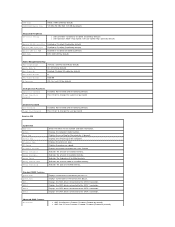
... Auto Power On Auto Power On Date Auto Power On Time S1(POS); Yes (Yes by default) l 3rd Boot Device-Removable; You can run the Dell Diagnostics on (or restart) your computer. 3. If you see the Microsoft Windows desktop. If you wait too long and the operating system logo appears, continue... connector. 2. Then shut down your computer to boot from the CD drive so that you want the computer to a USB device such as a floppy drive, memory key, or CD-RW drive. 1. Each device has a number next to restart your computer and try again. Disabled; ATA (ATA by default) Off; CD/DVD...
... Auto Power On Auto Power On Date Auto Power On Time S1(POS); Yes (Yes by default) l 3rd Boot Device-Removable; You can run the Dell Diagnostics on (or restart) your computer. 3. If you see the Microsoft Windows desktop. If you wait too long and the operating system logo appears, continue... connector. 2. Then shut down your computer to boot from the CD drive so that you want the computer to a USB device such as a floppy drive, memory key, or CD-RW drive. 1. Each device has a number next to restart your computer and try again. Disabled; ATA (ATA by default) Off; CD/DVD...
Service Manual
Page 36
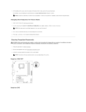
... to be bootable. To make sure your device is to a USB memory key, highlight USB Flash Device and press . For additional safety best practices information, see Removing the Computer Cover). 3. Inspiron 535/537 Inspiron 545 and down your computer. Use the arrow keys to highlight the... You Begin. 2. Changing Boot Sequence for the current boot only. Remove the computer cover (see the Regulatory Compliance Homepage at www.dell.com/regulatory_compliance. 1. NOTE: Write down -arrow keys to change the boot priority of the password connector may vary depending on the ...
... to be bootable. To make sure your device is to a USB memory key, highlight USB Flash Device and press . For additional safety best practices information, see Removing the Computer Cover). 3. Inspiron 535/537 Inspiron 545 and down your computer. Use the arrow keys to highlight the... You Begin. 2. Changing Boot Sequence for the current boot only. Remove the computer cover (see the Regulatory Compliance Homepage at www.dell.com/regulatory_compliance. 1. NOTE: Write down -arrow keys to change the boot priority of the password connector may vary depending on the ...
Service Manual
Page 40
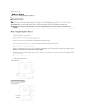
Back to Contents Page System Board Dell™ Inspiron™ 535/537/545/546 Service Manual Removing the System Board Replacing the System Board WARNING: Before working inside your computer, read the safety ...Heat Sink Assembly). 5. WARNING: Do not operate your equipment with your computer from the system board. Remove the memory modules (see Removing Memory) and document which memory module is replaced. 7. Inspiron 535/537 1 screws (6) 2 system board Inspiron 545/546 Remove any cover(s) (including computer covers, bezels, filler brackets, front-panel inserts, etc.) removed....
Back to Contents Page System Board Dell™ Inspiron™ 535/537/545/546 Service Manual Removing the System Board Replacing the System Board WARNING: Before working inside your computer, read the safety ...Heat Sink Assembly). 5. WARNING: Do not operate your equipment with your computer from the system board. Remove the memory modules (see Removing Memory) and document which memory module is replaced. 7. Inspiron 535/537 1 screws (6) 2 system board Inspiron 545/546 Remove any cover(s) (including computer covers, bezels, filler brackets, front-panel inserts, etc.) removed....

Service Manual
Page 42
6. Replace the computer cover (see Replacing PCI and PCI Express Cards). 8. Connect your computer and devices to Contents Page Back to an electrical outlet, and turn them (see Replacing Memory). 7. Replace any add-in cards on . Replace the memory modules into the memory sockets at the same locations from which you removed them on the system board (see Replacing the Computer Cover). 9.
6. Replace the computer cover (see Replacing PCI and PCI Express Cards). 8. Connect your computer and devices to Contents Page Back to an electrical outlet, and turn them (see Replacing Memory). 7. Replace any add-in cards on . Replace the memory modules into the memory sockets at the same locations from which you removed them on the system board (see Replacing the Computer Cover). 9.
Setup Guide
Page 5
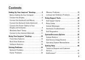
...Power Cables to Your Display and Computer 9 Windows Vista® Setup 10 Connect to the Internet (Optional 11 Using Your Inspiron™ Desktop 14 Front View Features 14 Back View Features 16 Software Features 18 Solving Problems 21 Network Problems 21 Power Problems 23... Memory Problems 24 Lockups and Software Problems 25 Using Support Tools 28 Dell Support Center 28 Beep Codes 29 System Messages 30 Hardware Troubleshooter 32 Dell Diagnostics 32 System Recovery Options 35 System Restore 36 Dell Factory Image Restore 37 Operating ...
...Power Cables to Your Display and Computer 9 Windows Vista® Setup 10 Connect to the Internet (Optional 11 Using Your Inspiron™ Desktop 14 Front View Features 14 Back View Features 16 Software Features 18 Solving Problems 21 Network Problems 21 Power Problems 23... Memory Problems 24 Lockups and Software Problems 25 Using Support Tools 28 Dell Support Center 28 Beep Codes 29 System Messages 30 Hardware Troubleshooter 32 Dell Diagnostics 32 System Recovery Options 35 System Restore 36 Dell Factory Image Restore 37 Operating ...
Setup Guide
Page 17
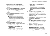
1 Optical drive panel eject button (2) - Using Your Inspiron™ Desktop • Solid amber - Supports a Media Card Reader, or an additional hard drive. 9 Optical drive panel (2) - Connects to the hard drive. 6 FlexBay panel - The ... a powered speaker or sound system, use the audio out connector on when the computer reads data from or writes data to USB devices such as memory keys, digital cameras, and MP3 players. 3 Headphone connector - there may be a problem with the system board. Open the FlexBay panel to headphones. Connects to access...
1 Optical drive panel eject button (2) - Using Your Inspiron™ Desktop • Solid amber - Supports a Media Card Reader, or an additional hard drive. 9 Optical drive panel (2) - Connects to the hard drive. 6 FlexBay panel - The ... a powered speaker or sound system, use the audio out connector on when the computer reads data from or writes data to USB devices such as memory keys, digital cameras, and MP3 players. 3 Headphone connector - there may be a problem with the system board. Open the FlexBay panel to headphones. Connects to access...
Setup Guide
Page 25
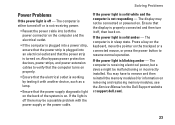
... strip is plugged into an electrical outlet and that the power supply diagnostic light on the back of the system is on the Dell Support website at support.dell.com). 23 If the power light is solid white and the computer is solid amber - The computer is receiving electrical power, but... off , then back on the trackpad or a connected mouse, or press the power button to remove and then reinstall the memory modules (for information on removing and replacing memory modules, see the Service Manual on . The computer is in sleep state. Solving Problems Power Problems If the power light is...
... strip is plugged into an electrical outlet and that the power supply diagnostic light on the back of the system is on the Dell Support website at support.dell.com). 23 If the power light is solid white and the computer is solid amber - The computer is receiving electrical power, but... off , then back on the trackpad or a connected mouse, or press the power button to remove and then reinstall the memory modules (for information on removing and replacing memory modules, see the Service Manual on . The computer is in sleep state. Solving Problems Power Problems If the power light is...

Setup Guide
Page 26
If necessary, install additional memory (see the Service Manual on the Dell Support website at support.dell.com). • Reseat the memory modules (see if that your computer - Memory Problems If you receive an insufficient memory message - • Save and close any open files and exit any open programs you encounter interference that hinders reception on the...
If necessary, install additional memory (see the Service Manual on the Dell Support website at support.dell.com). • Reseat the memory modules (see if that your computer - Memory Problems If you receive an insufficient memory message - • Save and close any open files and exit any open programs you encounter interference that hinders reception on the...

Setup Guide
Page 27
... Click End Task. NOTE: Software usually includes installation instructions in its documentation or on the Dell Support website at support.dell.com). • Check if the memory module is successfully communicating with your computer, see "Specifications" on page 50. • Run the... Dell Diagnostics (see "Dell Diagnostics" on page 32). • Reseat the memory modules (see the Service Manual on the Dell Support website at support.dell.com) to the electrical outlet. End the program: 1. Click Applications. 3....
... Click End Task. NOTE: Software usually includes installation instructions in its documentation or on the Dell Support website at support.dell.com). • Check if the memory module is successfully communicating with your computer, see "Specifications" on page 50. • Run the... Dell Diagnostics (see "Dell Diagnostics" on page 32). • Reseat the memory modules (see the Service Manual on the Dell Support website at support.dell.com) to the electrical outlet. End the program: 1. Click Applications. 3....
Setup Guide
Page 31
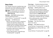
... in your computer. • If the problem persists contact Dell (see the Service Manual on the Dell Support website at support.dell.com). • Verify that the memory modules that no special memory module/ memory connector placement requirements exist (see the Service Manual on page 46). Seven beeps (Inspiron 535 and 545 only) - One beep - If the...
... in your computer. • If the problem persists contact Dell (see the Service Manual on the Dell Support website at support.dell.com). • Verify that the memory modules that no special memory module/ memory connector placement requirements exist (see the Service Manual on page 46). Seven beeps (Inspiron 535 and 545 only) - One beep - If the...
Setup Guide
Page 50
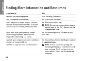
... Guide available on the Dell™ Support website at support.dell.com. NOTE: In some countries, opening and replacing parts of your Operating System disc. find your operating system. the Drivers and Utilities disc. INSPIRON Finding More Information and Resources If you need to: reinstall...See: your computer. Check your warranty and return policies before working inside your computer with new or additional memory, or a new hard drive. the Service Manual on the Dell Support website at support.dell.com. upgrade your computer. 48 learn more about your hard drive.
... Guide available on the Dell™ Support website at support.dell.com. NOTE: In some countries, opening and replacing parts of your Operating System disc. find your operating system. the Drivers and Utilities disc. INSPIRON Finding More Information and Resources If you need to: reinstall...See: your computer. Check your warranty and return policies before working inside your computer with new or additional memory, or a new hard drive. the Service Manual on the Dell Support website at support.dell.com. upgrade your computer. 48 learn more about your hard drive.
Setup Guide
Page 55
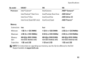
...and 2 GB 1 GB and 2 GB NOTE: For instructions on upgrading your memory, see the Service Manual on the Dell Support website at support.dell.com. 53 non-ECC memory only 800-MHz DDR2 DIMM; Specifications By model Processor 535/537 Intel® Celeron® Intel Pentium® Dual-Core Intel Core™2... Duo Intel Core2 Quad (537 only) 545 Intel Celeron Intel...
...and 2 GB 1 GB and 2 GB NOTE: For instructions on upgrading your memory, see the Service Manual on the Dell Support website at support.dell.com. 53 non-ECC memory only 800-MHz DDR2 DIMM; Specifications By model Processor 535/537 Intel® Celeron® Intel Pentium® Dual-Core Intel Core™2... Duo Intel Core2 Quad (537 only) 545 Intel Celeron Intel...


