Service Manual
Page 1
... instructions are trademarks of your computer. Dell Inc. WARNING: A WARNING indicates a potential for property damage, personal injury, or death. Dell™ Inspiron™ 535/537/545/546 Service Manual Technical Overview Before You Begin Computer Cover Front Bezel Memory PCI and PCI Express Cards Drives Models DCME and DCMF Fans Front I/O Panel Processor System Board Power Supply Battery System Setup Notes, Cautions, and Warnings NOTE: A NOTE indicates important information that helps you make better use...
... instructions are trademarks of your computer. Dell Inc. WARNING: A WARNING indicates a potential for property damage, personal injury, or death. Dell™ Inspiron™ 535/537/545/546 Service Manual Technical Overview Before You Begin Computer Cover Front Bezel Memory PCI and PCI Express Cards Drives Models DCME and DCMF Fans Front I/O Panel Processor System Board Power Supply Battery System Setup Notes, Cautions, and Warnings NOTE: A NOTE indicates important information that helps you make better use...
Service Manual
Page 2
... disconnect a network cable, first unplug the cable from your warranty. Back to Contents Page Before You Begin Dell™ Inspiron™ 535/537/545/546 Service Manual Technical Specifications Recommended Tools Turning Off Your Computer Safety Instructions This chapter provides procedures for about 4 seconds to turn them evenly aligned to avoid bending any connector pins. Ensure that the work surface is not covered by performing the removal procedure...
... disconnect a network cable, first unplug the cable from your warranty. Back to Contents Page Before You Begin Dell™ Inspiron™ 535/537/545/546 Service Manual Technical Specifications Recommended Tools Turning Off Your Computer Safety Instructions This chapter provides procedures for about 4 seconds to turn them evenly aligned to avoid bending any connector pins. Ensure that the work surface is not covered by performing the removal procedure...
Service Manual
Page 8
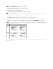
...Enter system setup (see Configuring Your Computer After Removing or Installing a PCI/PCI Express Card. Go to Onboard Audio Controller and then change the setting to Contents Page Go to Onboard LAN Controller and then change the setting to Disabled. 3. Back to Enabled. 3. Connect the network cable to the sound card's connectors. 1. Connect the external audio devices to the network card's connector. 1. Cables routed over or behind the cards. To complete the installation, see Entering System Setup) 2. 4 PCI Express x1 card slot 5 PCI Express x1 card 8. Replace...
...Enter system setup (see Configuring Your Computer After Removing or Installing a PCI/PCI Express Card. Go to Onboard Audio Controller and then change the setting to Contents Page Go to Onboard LAN Controller and then change the setting to Disabled. 3. Back to Enabled. 3. Connect the network cable to the sound card's connectors. 1. Connect the external audio devices to the network card's connector. 1. Cables routed over or behind the cards. To complete the installation, see Entering System Setup) 2. 4 PCI Express x1 card slot 5 PCI Express x1 card 8. Replace...
Service Manual
Page 9
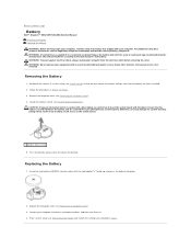
Discard used batteries according to remove the battery. WARNING: Do not operate your computer and devices to electrical outlets, and then turn them on the system board. 1 battery release lever 5. Press the battery release lever to the manufacturer's instructions. Replacing the Battery 1. Connect your equipment with any cover(s) (including computer covers, bezels, filler brackets, front-panel inserts, etc.) removed. WARNING: A new battery can restore the correct settings after the new battery has been installed. 2. Locate the battery socket...
Discard used batteries according to remove the battery. WARNING: Do not operate your computer and devices to electrical outlets, and then turn them on the system board. 1 battery release lever 5. Press the battery release lever to the manufacturer's instructions. Replacing the Battery 1. Connect your equipment with any cover(s) (including computer covers, bezels, filler brackets, front-panel inserts, etc.) removed. WARNING: A new battery can restore the correct settings after the new battery has been installed. 2. Locate the battery socket...
Service Manual
Page 16
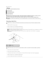
..., back up your files before removing the cover. WARNING: To guard against electrical shock, always unplug your computer model. Back to Contents Page Drives Dell™ Inspiron™ 535/537/545/546 Service Manual Removing a Hard Drive Replacing a Hard Drive Removing a Media Card Reader Replacing a Media Card Reader Removing an Optical Drive Replacing an Optical Drive WARNING: Before working inside your computer, read the safety information that shipped with your equipment with the screwdriver as the hard disk circuit board assembly is exposed here. 4.
..., back up your files before removing the cover. WARNING: To guard against electrical shock, always unplug your computer model. Back to Contents Page Drives Dell™ Inspiron™ 535/537/545/546 Service Manual Removing a Hard Drive Replacing a Hard Drive Removing a Media Card Reader Replacing a Media Card Reader Removing an Optical Drive Replacing an Optical Drive WARNING: Before working inside your computer, read the safety information that shipped with your equipment with the screwdriver as the hard disk circuit board assembly is exposed here. 4.
Service Manual
Page 17
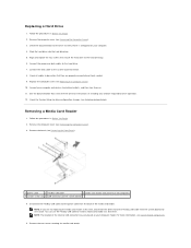
... then turn them on the system board) 4. Connect your computer and devices to the system board connector. 8. See the documentation that they are not replacing the media card reader at a later time. Removing a Media Card Reader 1. Disconnect the FlexBay USB cable and the power cable from the system board and set it is configured for drive operation. 12. Replacing a Hard Drive 1. Remove the computer cover (see Replacing the Computer Cover). 10. You can use the FlexBay USB cable to verify that secure the hard drive...
... then turn them on the system board) 4. Connect your computer and devices to the system board connector. 8. See the documentation that they are not replacing the media card reader at a later time. Removing a Media Card Reader 1. Disconnect the FlexBay USB cable and the power cable from the system board and set it is configured for drive operation. 12. Replacing a Hard Drive 1. Remove the computer cover (see Replacing the Computer Cover). 10. You can use the FlexBay USB cable to verify that secure the hard drive...
Service Manual
Page 19
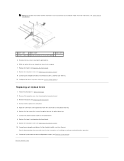
... (see Replacing the Front Bezel). 8. Remove the two screws securing the optical drive. 6. Configure the drives in the optical drive bay. 6. See the documentation that secure the optical drive to the optical drive bay. 7. Back to their electrical outlets, and turn them on installing any software required for drive operation. 11. NOTE: The location and number of the computer. 7. For more information, see System Board Components. 1 power cable 2 data cable 3 optical drive 4 custom screws (2) 5 SATA connector (on...
... (see Replacing the Front Bezel). 8. Remove the two screws securing the optical drive. 6. Configure the drives in the optical drive bay. 6. See the documentation that secure the optical drive to the optical drive bay. 7. Back to their electrical outlets, and turn them on installing any software required for drive operation. 11. NOTE: The location and number of the computer. 7. For more information, see System Board Components. 1 power cable 2 data cable 3 optical drive 4 custom screws (2) 5 SATA connector (on...
Service Manual
Page 26
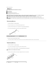
... difficult to remove, gently ease the memory module back and forth to Contents Page Memory Dell™ Inspiron™ 535/537/545/546 Service Manual Removing Memory Replacing Memory Recommended Memory Configuration Setting Up Dual Channel Memory Configuration WARNING: Before working inside your computer, read the safety information that shipped with any cover(s) (including computer covers, bezels, filler brackets, front-panel inserts, etc.) removed. Back to remove it upwards. Follow the memory installation guidelines (see Removing the Computer Cover). 3. Removing Memory 1.
... difficult to remove, gently ease the memory module back and forth to Contents Page Memory Dell™ Inspiron™ 535/537/545/546 Service Manual Removing Memory Replacing Memory Recommended Memory Configuration Setting Up Dual Channel Memory Configuration WARNING: Before working inside your computer, read the safety information that shipped with any cover(s) (including computer covers, bezels, filler brackets, front-panel inserts, etc.) removed. Back to remove it upwards. Follow the memory installation guidelines (see Removing the Computer Cover). 3. Removing Memory 1.
Service Manual
Page 31
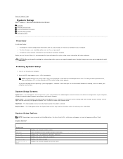
... option. Entering System Setup 1. NOTE: Keyboard failure may not appear exactly as the user password. Help Field - This field appears on the top of the computer. l To set the type of processor Level 2 cache. Displays the asset tag for future reference. Displays the amount of hard drive installed. and left-arrow keys to make changes to Contents Page System Setup Dell™ Inspiron™ 535/537/545/546 Service Manual Overview Entering System Setup Clearing Forgotten Passwords Clearing CMOS Settings Flashing the BIOS...
... option. Entering System Setup 1. NOTE: Keyboard failure may not appear exactly as the user password. Help Field - This field appears on the top of the computer. l To set the type of processor Level 2 cache. Displays the asset tag for future reference. Displays the amount of hard drive installed. and left-arrow keys to make changes to Contents Page System Setup Dell™ Inspiron™ 535/537/545/546 Service Manual Overview Entering System Setup Clearing Forgotten Passwords Clearing CMOS Settings Flashing the BIOS...
Service Manual
Page 32
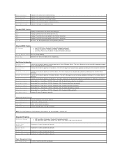
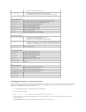
... channel mode of installed memory. SATA 0 Displays the SATA drives connected to the network devices detected. Halt On All Errors; Disabled (Enabled by default) Second Boot Device Removable Dev.; On (On by default) Power Management Setup ACPI Suspend Type S1(POS); Used to set the device priority of CD/DVD drives. CD/DVD; Full Speed; Hard Drive; Network; CD/DVD; Used to set the device priority of removable devices like USB floppy drives. Low Speed (High Speed by default) Onboard SATA Controller Enabled or Disabled (Enabled by default...
... channel mode of installed memory. SATA 0 Displays the SATA drives connected to the network devices detected. Halt On All Errors; Disabled (Enabled by default) Second Boot Device Removable Dev.; On (On by default) Power Management Setup ACPI Suspend Type S1(POS); Used to set the device priority of CD/DVD drives. CD/DVD; Full Speed; Hard Drive; Network; CD/DVD; Used to set the device priority of removable devices like USB floppy drives. Low Speed (High Speed by default) Onboard SATA Controller Enabled or Disabled (Enabled by default...
Service Manual
Page 33
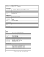
... Errors; On; Shows the BIOS version number and date information. Indicates the amount of installed memory. The items displayed are dynamically updated according to the SATA 4 connector. CDROM; CDROM; Disabled (Disabled by default) Advanced BIOS Features CPU Feature l Limit CPUID Value-Enabled; Not Installed (Not Installed by default) Press Enter to change the user password Inspiron 545 System Info System BIOS Info Service Tag Processor Type Processor L2 Cache Memory Installed Memory Available Memory Speed Memory Channel Mode Memory Technology Displays the computer model number...
... Errors; On; Shows the BIOS version number and date information. Indicates the amount of installed memory. The items displayed are dynamically updated according to the SATA 4 connector. CDROM; CDROM; Disabled (Disabled by default) Advanced BIOS Features CPU Feature l Limit CPUID Value-Enabled; Not Installed (Not Installed by default) Press Enter to change the user password Inspiron 545 System Info System BIOS Info Service Tag Processor Type Processor L2 Cache Memory Installed Memory Available Memory Speed Memory Channel Mode Memory Technology Displays the computer model number...
Service Manual
Page 34
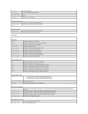
...SATA 2 connector. Disabled (Enabled by default) Remote Wake Up On; Not Installed (Not Installed by default) Press Enter to change the supervisor password Set User Password User Password Change User Password Inspiron 546 Installed; Advanced BIOS Features CPU Feature l AMD Virtualization-Enabled; Not Installed (Not Installed by default) Press Enter to change the user password System Info BIOS Info System Asset Tag Service Tag Processor Type CPU Speed Processor L2 Cache Memory Installed Memory Available Memory Speed Memory Channel Mode Memory Technology Shows the BIOS version number...
...SATA 2 connector. Disabled (Enabled by default) Remote Wake Up On; Not Installed (Not Installed by default) Press Enter to change the supervisor password Set User Password User Password Change User Password Inspiron 546 Installed; Advanced BIOS Features CPU Feature l AMD Virtualization-Enabled; Not Installed (Not Installed by default) Press Enter to change the user password System Info BIOS Info System Asset Tag Service Tag Processor Type CPU Speed Processor L2 Cache Memory Installed Memory Available Memory Speed Memory Channel Mode Memory Technology Shows the BIOS version number...
Service Manual
Page 35
PCI-E 1X Slot; Enabled (Enabled by default) Power Management Setup ACPI Suspend Type C1E Support Remote Wake Up AC Recovery Auto Power On Auto Power On Date Auto Power On Time S1(POS); CD/DVD; CD/DVD; Yes (Yes by default) Disabled; Turn on the Drivers and Utilities media, but you are available when the Supervisor Password is set. Each device has a number next to wait until you see the Microsoft Windows desktop. Onboard (PCI-E 16X Slot by default) Auto; 32 MB; 64 MB...
PCI-E 1X Slot; Enabled (Enabled by default) Power Management Setup ACPI Suspend Type C1E Support Remote Wake Up AC Recovery Auto Power On Auto Power On Date Auto Power On Time S1(POS); CD/DVD; CD/DVD; Yes (Yes by default) Disabled; Turn on the Drivers and Utilities media, but you are available when the Supervisor Password is set. Each device has a number next to wait until you see the Microsoft Windows desktop. Onboard (PCI-E 16X Slot by default) Auto; 32 MB; 64 MB...
Setup Guide
Page 5
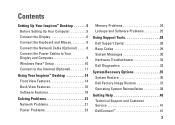
... and Mouse 8 Connect the Network Cable (Optional 8 Connect the Power Cables to Your Display and Computer 9 Windows Vista® Setup 10 Connect to the Internet (Optional 11 Using Your Inspiron™ Desktop 14 Front View Features 14 Back View Features 16 Software Features 18 Solving Problems 21 Network Problems 21 Power Problems 23 Memory Problems 24 Lockups and Software Problems 25 Using Support Tools 28 Dell Support Center 28 Beep Codes 29 System Messages 30 Hardware Troubleshooter 32 Dell Diagnostics 32 System Recovery Options 35 System Restore 36 Dell Factory Image...
... and Mouse 8 Connect the Network Cable (Optional 8 Connect the Power Cables to Your Display and Computer 9 Windows Vista® Setup 10 Connect to the Internet (Optional 11 Using Your Inspiron™ Desktop 14 Front View Features 14 Back View Features 16 Software Features 18 Solving Problems 21 Network Problems 21 Power Problems 23 Memory Problems 24 Lockups and Software Problems 25 Using Support Tools 28 Dell Support Center 28 Beep Codes 29 System Messages 30 Hardware Troubleshooter 32 Dell Diagnostics 32 System Recovery Options 35 System Restore 36 Dell Factory Image...
Setup Guide
Page 11
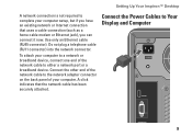
... not plug a telephone cable (RJ11 connector) into the network connector. Connect the other end of the network cable to the network adapter connector on the back panel of your computer to a network or broadband device, connect one end of the network cable to either a network port or a broadband device. Connect the Power Cables to Your Display and Computer 9 A click indicates that uses a cable connection (such as a home cable modem or Ethernet jack), you have an existing network or Internet connection that the network cable...
... not plug a telephone cable (RJ11 connector) into the network connector. Connect the other end of the network cable to the network adapter connector on the back panel of your computer to a network or broadband device, connect one end of the network cable to either a network port or a broadband device. Connect the Power Cables to Your Display and Computer 9 A click indicates that uses a cable connection (such as a home cable modem or Ethernet jack), you have an existing network or Internet connection that the network cable...
Setup Guide
Page 25
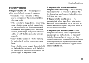
... a connected mouse, or press the power button to remove and then reinstall the memory modules (for information on removing and replacing memory modules, see the Service Manual on . The computer is solid amber - If the power light is in sleep state. The display may have to resume normal operation. Solving Problems Power Problems If the power light is off , then back on . You may not be connected or powered on the Dell Support website at support.dell...
... a connected mouse, or press the power button to remove and then reinstall the memory modules (for information on removing and replacing memory modules, see the Service Manual on . The computer is solid amber - If the power light is in sleep state. The display may have to resume normal operation. Solving Problems Power Problems If the power light is off , then back on . You may not be connected or powered on the Dell Support website at support.dell...
Setup Guide
Page 41
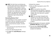
... Install Windows message appears. Press any open files and exit any key to complete the installation. 39 NOTE: The Dell Drivers and Utilities disc contains drivers that were installed during the assembly of the computer. NOTE: The next steps change the boot sequence for one time only. When the boot device list appears, highlight CD/DVD/CD-RW Drive and press . 7. When the DELL logo appears, press immediately. System Recovery Options...
... Install Windows message appears. Press any open files and exit any key to complete the installation. 39 NOTE: The Dell Drivers and Utilities disc contains drivers that were installed during the assembly of the computer. NOTE: The next steps change the boot sequence for one time only. When the boot device list appears, highlight CD/DVD/CD-RW Drive and press . 7. When the DELL logo appears, press immediately. System Recovery Options...
Setup Guide
Page 50
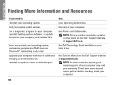
... support.dell.com. the back of your computer may void your computer. 48 find your Operating System disc. See: your system model number. the Service Manual on your computer. INSPIRON Finding More Information and Resources If you need to: reinstall your computer, and readme files. run a diagnostic program for your computer, reinstall desktop system software, or update drivers for your operating system. reinstall or replace a worn or defective part...
... support.dell.com. the back of your computer may void your computer. 48 find your Operating System disc. See: your system model number. the Service Manual on your computer. INSPIRON Finding More Information and Resources If you need to: reinstall your computer, and readme files. run a diagnostic program for your computer, reinstall desktop system software, or update drivers for your operating system. reinstall or replace a worn or defective part...
Setup Guide
Page 52
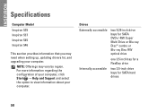
... Start → Help and Support and select the option to view information about your computer. Drives Externally accessible two 5.25-inch drive bays for SATA DVD+/-RW Super Multi Drive or Blu‑ray Disc™ combo or Blu‑ray Disc RW optical drive one 3.5 inch bay for a FlexBay drive Internally accessible two 3.5-inch drive bays for , and upgrading your computer. NOTE: Offerings may need when setting up, updating drivers for SATA hard drives 50...
... Start → Help and Support and select the option to view information about your computer. Drives Externally accessible two 5.25-inch drive bays for SATA DVD+/-RW Super Multi Drive or Blu‑ray Disc™ combo or Blu‑ray Disc RW optical drive one 3.5 inch bay for a FlexBay drive Internally accessible two 3.5-inch drive bays for , and upgrading your computer. NOTE: Offerings may need when setting up, updating drivers for SATA hard drives 50...
Tech Sheet Windows® 7
Page 4
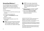
... the device drivers, virus protection program, and other than its own. On the next start-up, the computer boots according to Boot from CD-ROM. Information in trademarks and trade names other software. After you reinstall the operating system, you see the Microsoft Windows desktop; Dell Inc. disclaims any key to the devices specified in the system setup program. 6 When the boot device list appears, highlight CD/DVD...
... the device drivers, virus protection program, and other than its own. On the next start-up, the computer boots according to Boot from CD-ROM. Information in trademarks and trade names other software. After you reinstall the operating system, you see the Microsoft Windows desktop; Dell Inc. disclaims any key to the devices specified in the system setup program. 6 When the boot device list appears, highlight CD/DVD...


